DOI:
10.1039/D0NA00519C
(Review Article)
Nanoscale Adv., 2020,
2, 4341-4349
Rare-earth-free magnetically hard ferrous materials
Received
24th June 2020
, Accepted 25th July 2020
First published on 28th July 2020
Abstract
Permanent magnets, especially rare-earth based magnets, are widely used in energy-critical technologies in many modern applications, involving energy conversion and information technologies. However, the environmental impact and strategic supplies of rare-earth elements hamper the long-term development of permanent magnets. Hence, there is a surge of interest to expand the search for rare-earth-free magnets with a large energy product (BH)max. Among these rare-earth-free magnets, iron-based permanent magnets emerge as some of the most promising candidates due to their abundance and magnetic performance. In this review, we present a summary of iron-based permanent magnets from materials synthesis to their magnetic properties.
 Zefan Shao | Mr. Zefan Shao is a graduate student of Mechanical and Aerospace Engineering at the University at Buffalo, The State University of New York. He joined the laboratory of Prof. Shenqiang Ren, working on solution-based synthesis of colloidal functional nanomaterials. His research interests focus on functional metal and alloy nanoparticles. |
 Shenqiang Ren | Dr. Shenqiang Ren is Professor of Mechanical and Aerospace Engineering, and Chemistry at SUNY-Buffalo, with research interests in emerging functional materials and devices. He earned his PhD degree in Materials Science and Engineering at the University of Maryland College Park, and then served as a postdoctoral fellow at the Massachusetts Institute of Technology (MIT). He received the 2015 National Science Foundation – CAREER Award, 2014 Army Research Office – Young Investigator Award, 2013 NSF EPSCOR First Award, 2013 Air Force Summer Faculty Fellowship, 2009 Dean's Doctoral Research Award and Distinguished Doctoral Dissertation Award at the University of Maryland, College Park. |
1 Introduction
Permanent magnets have received intense interest due to their applications in energy-critical technologies, such as wind turbine, electric vehicles and information storage.1–8 The essential measure of permanent magnets is the energy product,9,10 which is defined as the product of B and H in the second quadrant hysteresis curve.11,12 Rare-earth magnets include neodymium magnets and samarium–cobalt magnets.13–15 However, considering the rapidly increasing demand for rare-earth elements in various areas (Fig. 1a), much attention has been focused on searching for new alternative magnets with rare-earth-free elements.16,17 The rare-earth-free magnetic materials with high magneto-crystalline anisotropy and energy product exhibit promising potential for use as permanent magnets (Fig. 1b and Table 1).16,18
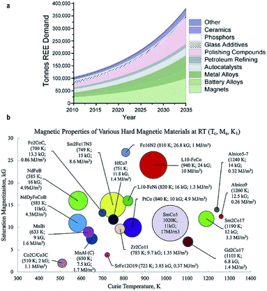 |
| | Fig. 1 (a) Evolution of market distribution of REE demand; (b) magnetic properties of various hard magnetic materials. Reproduced from ref. 16,17 and 18 with the permission of Elsevier, American Chemical Society and Springer Nature. | |
Table 1 Magnetic properties of rare-earth-free magnets
Among many pursued rare-earth-free elements, iron has been emerging as one of the most promising candidates due to its abundance and large saturation magnetization.19,20 The ferrites have shown their applications in navigation from ancient times.11,21 Iron-based magnets with a large coercivity, such as FePd, FePt, FeCo, Fe12N2, ε-Fe2O3, FeNi and Fe3Se4, would present great potential for green energy applications due to their high saturation magnetization and magnetocrystalline anisotropy. In this context, the tetragonal L10-ordered phase of FePd and FePt can achieve an optimum coercivity of 16 kOe, whereas the FeCo alloy has shown a higher value of uniaxial magnetocrystalline anisotropy (Ku) of 1 × 10⁷ J.22,23 Meanwhile, the magnetic energy product for the Fe16N2 phase can reach 20 MGOe.19,24 In the past several decades, much attention and efforts have been focused on investigating the manufacturing routes and magnetic properties of these iron-based materials.25,26 Hard ferrites, some of the least expensive and most common magnets, are composed of fine particles with a tetragonal crystal structure.27 These iron-based permanent magnets, combined with Ba or Sr, exhibit a pronounced coercivity but relatively low magnetization, attributed to the coexistence of ferromagnetic and antiferromagnetic coupling.28 The magnetization of these magnets is temperature-dependent and shows an abrupt transition point due to the phase transformation.29 Alternatively, high coercivity can also be triggered by the dimension and morphology of ferrite hard magnets within the single domain region.30 The ferrite magnets could exhibit tuneable coercivity (Hc) due to the varied particle size and stoichiometry.31 Moreover, magnetic properties can be influenced by the exchange coupling interaction between magnetically hard and soft phases.32,33 In this review, we summarize the strategies for the synthetic control of magnetic properties in iron-based magnets.34,35
2 Preparation and magnetic properties of iron-based ferrous materials
Iron-based ferrous materials are some of the rare-earth-free hard magnets with a large uniaxial magnetocrystalline anisotropy.52 Iron-based magnets, particularly the tetragonal L10 ordered phase, show promising applications in information storage and electrical machine systems due to their large magnetic anisotropy and high coercivity.18,53,54 Therefore, intense attention has been focused on the formation of the L10-ordered phase in iron-based magnets.55
2.1 Iron cobalt hard magnet
The FeCo alloy, an important magnetic material, is very attractive due to its high saturation magnetization (Ms) and Curie temperature (Tc) among transition metal alloys, while its small coercive field and low magnetocrystalline anisotropy indicate its soft nature.56 However, tetragonal distorted FeCo alloys could turn FeCo alloys into hard magnets with high coercivity.16 The theoretical calculations achieved by Wu et al. in 2008 showed a giant uniaxial magnetocrystalline anisotropy and saturation magnetization in body-centered-tetragonal FeCo alloys (Fig. 2a).57
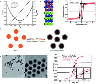 |
| | Fig. 2 (a) The calculated total energy (ΔE) and magnetocrystalline anisotropy energy (EMCA) of FeCo along the (001) direction; (b) a schematic illustration of the crystal structure of FeCo/FePt(001); (c) magnetic hysteresis loops for an FeCo/FePt thin film; (d) schematic figure of the AuCu/FeCo (core/shell) nanocrystal synthesis; (e) the TEM image of AuCu/FeCo (core/shell) nanoparticles; (f) the M–H loops of L10 AuCu/FeCo particles. The inset shows the annealing temperature-dependent coercivity of L10 AuCu/FeCo. Reproduced from ref. 42, 45, 46 and 48 with the permission of AIP Publishing, Elsevier and American Chemical Society. | |
The possibility of achieving high magnetocrystalline anisotropy in FeCo alloys was initially inspired by straining metal films on a templated substrate. In 2006, Winkelmann, et al. reported the perpendicular magnetic anisotropy induced by pure Fe and Co films grown on Pd (001), showing that the anisotropy energy can be improved by a tetragonal crystal structure.58 A suitable range of lattice-parameter ratios, known as c/a values, can promote the formation of tetragonal FeCo, which were proved to be between 1.18 and 1.31 by Warnicke et al. in 2007.59 The exact prerequisites, obtained using the c/a ratio, promote the synthesis of a tetragonal crystal structure of an FeCo alloy and provide a potential direction for high magnetocrystalline anisotropy. In 2012, Kim and Hong reported that the energy product of FeCo grown on an FePt (001) substrate, as shown in Fig. 2b, can reach 66 MGOe and the maximum coercivity, guided by a full potential linearized augmented plane wave (FLAPW) method, is 188 kOe.60 In 2015, Giannopoulos introduced an advanced FeCo ultrathin layer grown on an L10 FePt film, which shows a maximum energy product of up to 50 MGOe and a maximum coercive field of 50 kOe, as shown in Fig. 2c.61 These discoveries clearly show the potential applications of FeCo alloys in permanent magnets. In 2014, the interstitial boron doped FeCo, introduced by Khan and Hong, indicated that the magnetocrystalline anisotropy constant can reach 0.8 MJ m−3 with an estimated energy product of 100 MGOe.62 The preparation of tetragonal distorted FeCo magnets reported so far has been through similar routes by synthesizing under a high temperature and oxygen-free environment. The average diameter of FeCo particles, synthesized in this method, inevitably increases with the rise of temperature. The magnetic properties, such as coercivity, can be weakened with a large size of FeCo particles. A long-standing challenge of controlling the particle size has been overcome by utilizing an AuCu/FeCo (core/shell) structure (Fig. 2d), introduced by Ren in 2014. This approach presents a tetragonal FeCo microstructure which is induced by the L10 ordering of the AuCu core, with an average diameter of 10 nm and a significantly high coercivity and magnetization with the values of 846 Oe and 221 emu g−1, as shown in Fig. 2e and f.63
2.2 Iron platinum and iron palladium hard magnets
Precious metal ferromagnets, such as FePd and FePt, have shown a large magnetocrystalline anisotropy due to their crystal structure.64 The L10 ordered FePd and FePt alloys show a large magnetocrystalline anisotropy.18 The microstructure of hard magnet FePd is dominated by a face-centered-tetragonal lattice.
2.2.1 Iron palladium.
Iron palladium (FePd) alloys, achieving high magnetocrystalline anisotropy and energy density, attract intense interest due to their broad applications ranging from data storage to ferrofluids.65 The colloidal solution synthesis of hard magnetic FePd particles is one of the most studied ones. The formation of a tetragonal FePd lattice, triggered by high temperature sintering, makes the FePd particles exhibit a hard magnetic performance.66 The phase transformation, induced by high temperature conditions, cannot always control the size of annealed FePd nanoparticles during the sintering process.67 The simultaneous chemical reaction introduced by Chen and Nikles in 2002 was operated in a three-neck flask by the reduction of palladium acetylacetonate and thermal decomposition of iron pentacarbonyl, which achieved an optimal coercivity of 685 Oe as shown in Table 2.68 The ordering parameter S, presented in Table 1, was calculated using unit cell parameters (a, c) obtained by X-ray diffraction quantification. The FePd nanoparticles would reach an average diameter of 11 nm after annealing at 700 °C for 3 hours. The development of this simultaneous reaction was limited by its high energy requirement and a lengthy reaction time. In 2006, Watanabe and Sato et al. reported a synthesis route for FePd nanoparticles that can be applied in the recording media and fabricated by an electron-beam evaporation technique. The value of the optimal coercivity can reach 1.2 kOe after annealing at 773 K for 1 h (Fig. 3a).69,70 Meanwhile, the FePd nanoparticles introduced by Sato et al. in 2000 were synthesized by a modified polyol process, showing the thermal treatment effect on magnetic properties.71 Besides, in 2004 Hou et al. reported monodisperse FePd nanoparticles, controlled by the ratio and type of stabilizer, presenting an average diameter of 13.5 nm and an optimal coercivity of 350 Oe, as shown in Fig. 3b.72 The exchange-coupling also played an important role in controlling the formation of L10-FePd. In 2013, Yu et al. reported a one-pot synthesis of L10-FePd-Fe (Fig. 3c), which was controlled by a thermodynamically stable mixture, with the lattice fringe spacings of 0.27 nm and 0.20 nm (Fig. 3d), indicating an optimal coercivity of 2.6 kOe and a saturation magnetization of 190 emu g−1, as shown in Fig. 3e.73 A eutectic reaction, known as liquid phase transformation, is based on a solid-state eutectic composition with low melting point to minimize energy consumption which leads to a low-cost manufacturing process. Therefore, an understanding of microstructure formation guided by a eutectic reaction is essential for the exploration of advanced magnetic nanoparticle formation. In 2020, Ren introduced a eutectic crystallization approach into the synthesis of FePd nanoparticles with high coercivity.74
Table 2 The order parameter and coercivity of an FePd film at different annealing temperatures. Reproduced from ref. 53 with the permission of AIP Publishing
| Temperature (°C) |
As-prepared |
550 |
600 |
700 |
700 |
| Time (min) |
0 |
30 |
30 |
60 |
180 |
| Condition |
Vacuum |
Vacuum |
Vacuum |
Ar–H2 |
Ar–H2 |
|
a (ppm) |
386 |
383 |
381 |
381 |
379 |
|
c (pm) |
386 |
383 |
381 |
381 |
379 |
|
S
|
0 |
0 |
0 |
0 |
0 |
|
H
c (Oe) |
12 |
685 |
548 |
421 |
297 |
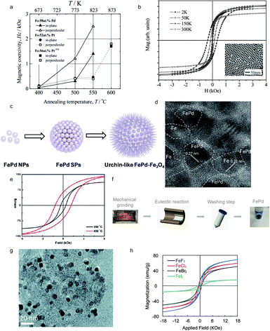 |
| | Fig. 3 (a) Annealing temperature dependence of coercivity for FePd nanoparticles dispersed on NaCl (001) substrates covered with a-Al2O3 thin films; (b) magnetic hysteresis loops and TEM image of monodisperse FePd; (c) schematic illustration of self-aggregation of FePd–Fe; (d) high-resolution (HRTEM) image of the L10-FePd-Fe nanoparticles; (e) magnetic hysteresis loops of FePd nanoparticles which are controlled by the exchange-coupling method at different temperatures; (f) eutectic salt melt synthesis and crystallization of FePd powder prepared by a eutectic reaction; (g) the TEM image of FePd nanoparticles prepared by a eutectic reaction; (h) magnetic hysteresis loops of FePd with different precursors prepared by a eutectic reaction. Reproduced from ref. 54, 55, 57, 58 and 59 with the permission of IOP Publishing, Elsevier, American Chemical Society and Royal Society of Chemistry. | |
The schematic eutectic salt melt route, a powder metallurgical method, considers KCl–LiCl as a salt solvent to prepare FePd particles, as shown in Fig. 3f. The TEM image of FePd nanoparticles indicates the average diameter of FePd (50 nm), as shown in Fig. 3g. Fig. 3h illustrates the magnetization–hysteresis (M–H) loops of the as-synthesized FePd nanoparticles, which are prepared using different halide precursors with the same ratio between Fe and Pd. Meanwhile, the optimal precursor for FePd is FeI2 with a coercivity of 1800 Oe and a magnetization of 17 emu g−1.74 The eutectic salt melt method can effectively avoid the sintering induced aggregation of magnetic nanoparticles during phase transformation and simplifies the preparation procedure of FePd magnets.
2.2.2 Iron platinum.
Iron platinum (FePt), face-centered-cubic (FCC) phase, can be transformed into a face-centered-tetragonal (FCT) phase with a large magnetocrystalline anisotropy after a high temperature thermal annealing.75 During the past few decades, researchers have developed many synthetic routes to attain FePt with a FCT lattice microstructure, such as one-step thermal synthesis with metal precursors, water-in-oil microemulsion and exchange-coupled assembly. In 1935, L10 FePt alloys, with a magnetocrystalline anisotropy of 66 Merg cm−3, were synthesized by Graf and Kussmann.76 The ordered L10 FePt alloys can be generated by annealing FCC FePt at a certain temperature which is above the FCT ordering temperature. In 2003, Jeyadevan reported a chemical route, achieving the transition of the FCT crystal structure of FePt, with an optimal coercivity of 1.7 kOe at 10 K, as shown in Fig. 4a.77 Through the decomposition of platinum acetylacetonate and iron pentacarbonyl in the presence of oleic acid and oleylamine, monodisperse FePt was successfully prepared in 2000 by Sun et al.78 In 2003, Sun's group reported fct-FePt (Fig. 4b) nanoparticles obtained from a chemical reaction route, showing a high coercivity of 7.6 kOe (Fig. 4c).79 The chemical synthesis routes for FePt were the dominating routes in the past few decades. Meanwhile, a long-existing challenge is the aggregation of FePt nanoparticles induced by thermal annealing beyond the single-domain region. In 2004, the synthesis of FePt nanoparticles with tunable size was introduced by Chun et al., where the average diameter of FePt was 6 nm (Fig. 4d and e) and the room temperature coercivity reached 13 kOe.80 The transformation of the face-centered-tetragonal phase generated from the disordered FCC crystal structure requires a reaction temperature above 650 °C, while the morphology and structure of FePt nanoparticles are likely to be destroyed during the sintering process due to the relatively high temperature. In 2019, Ren et al. developed an annealing route known as eutectic melt crystallization of ordered L10-FePt to synthesize an ordered face-cubic-tetragonal FePt alloy, as shown in Fig. 4f. The as-synthesized L10-FePt particles exhibited a coercivity of 16 kOe and a saturation magnetization of 33.6 emu g−1 with the optimal energy product reaching 5.0 MGOe, as shown in Fig. 4g–i.81
2.3 Fe16N2
The Fe16N2 magnet, one of the promising permanent magnet candidates, exhibits a giant saturation magnetization.82 The synthesis of bulk α′′-Fe16N2 was reported (Fig. 5a).83 In 1972, Kim and Takahashi studied the saturation magnetization and magnetic moment of α′′-Fe16N2 which showed a saturation magnetization of 2000 emu cm−3, as shown in Fig. 5b, which is larger than that of FeCo.84 Due to its high magnetic performance, much attention was paid to the exploration of different types of α′′-Fe16N2, such as bulk, nanoparticles and thin films. Subsequently, various synthesis routes were reported, such as the preparation of α′′-Fe16N2 nanoparticles using compounds containing Fe2O3 and NH3–H2 mixed gas, introduced by Bao and Metzger in 1994.85 These methods mostly produced multiple phases, including α′′-Fe16N2, while the magnetic properties can be influenced by the volume ratio of α′′-Fe16N2 (Table 3). In 2016, Wang et al. reported a route for the synthesis of Fe16N2 by ball milling and shock compaction, achieving a high saturation magnetization of 210 emu g−1 and a large coercivity (Hc) of 854 Oe, as shown in Fig. 5c.86Fig. 5d suggests that the coercivity of the synthesized free-standing Fe16N2 foil can reach 1910 Oe. The value of the magnetic energy product of Fe16N2 can reach 20 MGOe at room temperature, proving the potential applications in permanent magnets, as shown in Fig. 5e. Fig. 5f indicates the crystalline structure through the TEM diffraction pattern.19
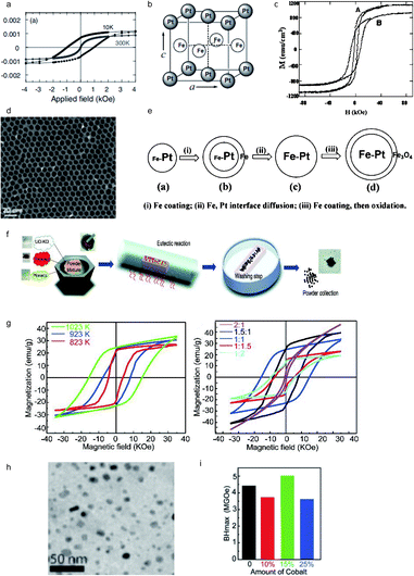 |
| | Fig. 4 (a) Magnetic hysteresis loops of FePt prepared by a chemical route at 10 K; (b) schematic illustration of chemically ordered fct-FePt; (c) the TEM image of monodisperse FePt; (d) TEM bright field images of tunable FePt particles; (e) schematic illustration of the FePt nanoparticle formation mechanism; (f) schematic illustration of the synthesis of L10-FePt; (g) the TEM image of L10-FePt nanoparticles; (h) magnetic hysteresis loops of L10-FePt nanoparticles; (i) the calculated energy product of FePt–Co magnets. Reproduced from ref. 62, 64, 65 and 66 with the permission of IOP Publishing, American Chemical Society and Royal Society of Chemistry. | |
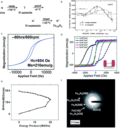 |
| | Fig. 5 (a) The formation sequence of Fe16N2; (b) magnetic hysteresis loops of Fe16N2 prepared by ball milling and shock compaction; (c) saturation magnetization of Fe films against pressure which were separately deposited in a nitrogen atmosphere and vacuum; (d) magnetic hysteresis loops of Fe16N2 at room temperature; (e) the calculated energy product for Fe16N2 at room temperature; (f) the TEM diffraction pattern of Fe16N2 with 5 × 10¹⁷ions per cm2 fluence. Reproduced from ref. 68, 69, 71 and 20 with the permission of Elsevier, AIP Publishing, John Wiley and Sons and Springer Nature. | |
Table 3 Magnetic properties of Fe16N2. Reproduced from ref. 70 with the permission of AIP Publishing
| Species |
Site |
H
hf
|
ΔEQ |
IS |
| α′′-Fe16N2 |
FeI |
292 |
−0.17 |
0.01 |
| α′′-Fe16N2 |
FeII |
397 |
−0.04 |
0.07 |
| α′′-Fe16N2 |
FeIII |
317 |
0.15 |
0.10 |
| α-Fe |
— |
330 |
0 |
0 |
| γ-Austenite |
— |
— |
— |
0.04 |
|
|
— |
— |
0.37 |
0.07 |
2.4 ε-Fe2O3
Iron oxides exist as different crystalline polymorphs, such as α-, β-, γ-, and ε-Fe2O3.87 Among these iron oxides, ε-Fe2O3 is of much interest due to its unique magnetic properties.88 The ε-Fe2O3 formed under exclusively high temperature conditions exhibits potential applications in recording media and microwave devices.89 The silica template methods, depending on the chemical reaction, have been the most common synthesis routes in the past several decades. In 2004, Jin, Ohkoshi and Hashimoto reported nanosized ε-Fe2O3, prepared in a silica matrix, which showed a giant coercive field of 20 kOe at room temperature (Fig. 6a).90 In 2008, Sakurai et al. introduced an advanced route to synthesize ε-Fe2O3 nanoparticles with an average diameter of 7 nm by combining the reverse-micelle and sol–gel methods (Fig. 6b), as shown in Fig. 6c.91 In 2012, Namai reported a nanocrystalline ε-Fe2O3 (Fig. 6d), prepared by a nanoscale chemical synthesis in a silica template (Fig. 6e), presenting a large coercivity value of 31 kOe (Fig. 6f).92 The two-step magnetic transition was dependent on temperature and the external magnetic field. In 2015, Kohout et al. reported 57Fe isotope enriched ε-Fe2O3, prepared by a sol–gel technique in a silica template, which exhibited a coercivity HC of 21 kOe at 300 K, as shown in Fig. 6g.93 A significant improvement of magnetic properties for ε-Fe2O3 was reported by Ohkoshi et al. in 2017.94 The attained ε-Fe2O3, prepared using metal instead of traditional iron ions, showed the highest coercivity of 45 kOe at 200 K, as shown in Fig. 6h.
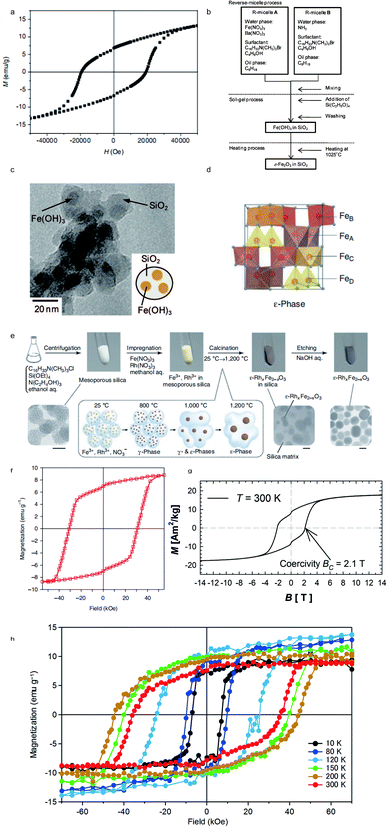 |
| | Fig. 6 (a) Magnetic hysteresis loops of ε-Fe2O3 prepared by Jin et al.; (b) procedure to prepare SiO2-coated ε-Fe2O3 nanorods; (c) TEM image of ε-Fe2O3; (d) crystal structure of the ε-phase; (e) schematic illustration of synthesis of ε-Fe2O3 on a silica template; (f) magnetic hysteresis loops of oriented ε-Fe2O3 at 300 K; (g) magnetic hysteresis loops of powdered ε-Fe2O3 embedded in a silica matrix at 300 K; (h) magnetic hysteresis loops of ε-Fe2O3 oriented at different temperatures. Reproduced from ref. 75, 76, 77, 78 and 79 with the permission of John Wiley and Sons, Springer Nature, and AIP Publishing. | |
2.5 FeNi
The L10-FeNi phase, known as tetrataenite (Fe50Ni50), is one of the rare-earth-free magnet candidates.95 In 1962, Pauleve et al. reported L10-FeNi induced by neutron irradiation and annealed at 593 K under a magnetic field.96 The order–disorder transition temperature of L10-FeNi is shown to be 593 K, further proved by Reuter et al. in 1989 under electron irradiation.97 As the atomic jump of nickel in FeNi alloys could take more than 10![[thin space (1/6-em)]](https://www.rsc.org/images/entities/char_2009.gif) 000 years at 573 K,98 L10-FeNi is only found naturally in meteorites.99 In 2015, Poirier et al. introduced tetragonal L10-FeNi obtained from the meteorite NWA 6259, presenting a large anisotropy field of 14.4 kOe (Fig. 7a).41 Furthermore, in 2016 Lewis et al. reported tetragonal FeNi that was generated through an annealing protocol and pointed out the crystal structure transition of the FeNi lattice from a cubic to tetragonal unit cell, as shown in Fig. 7b.100 Meanwhile, the chemical synthesis of L10-FeNi was also presented by Hayashi et al. in 2013. The L10-FeNi alloy, prepared by a reductive reaction, showed a maximum coercivity of 220 kA m−1 (2765 Oe).101 However, the stabilization of tetragonal FeNi alloys is a challenging task. In order to overcome this challenge, Ren introduced a rational epitaxial core/shell design to stabilize tetragonal FeNi nanocrystals (Fig. 7c). The reconstruction of tetragonal FeNi was triggered by the surface stress due to the existence of AuCu cores, as shown in Fig. 7d. The designed FeNi exhibited a large coercivity of 1010.2 Oe and a saturation magnetization of 122 emu g−1, as shown in Fig. 7e.102
000 years at 573 K,98 L10-FeNi is only found naturally in meteorites.99 In 2015, Poirier et al. introduced tetragonal L10-FeNi obtained from the meteorite NWA 6259, presenting a large anisotropy field of 14.4 kOe (Fig. 7a).41 Furthermore, in 2016 Lewis et al. reported tetragonal FeNi that was generated through an annealing protocol and pointed out the crystal structure transition of the FeNi lattice from a cubic to tetragonal unit cell, as shown in Fig. 7b.100 Meanwhile, the chemical synthesis of L10-FeNi was also presented by Hayashi et al. in 2013. The L10-FeNi alloy, prepared by a reductive reaction, showed a maximum coercivity of 220 kA m−1 (2765 Oe).101 However, the stabilization of tetragonal FeNi alloys is a challenging task. In order to overcome this challenge, Ren introduced a rational epitaxial core/shell design to stabilize tetragonal FeNi nanocrystals (Fig. 7c). The reconstruction of tetragonal FeNi was triggered by the surface stress due to the existence of AuCu cores, as shown in Fig. 7d. The designed FeNi exhibited a large coercivity of 1010.2 Oe and a saturation magnetization of 122 emu g−1, as shown in Fig. 7e.102
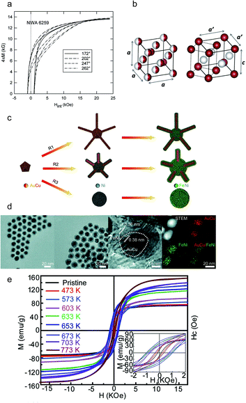 |
| | Fig. 7 (a) Magnetic hysteresis of NWA 6259 tetrataenite; (b) representations of the cubic (A1) and tetragonal (L10) unit cells of FeNi; (c) schematic images of the synthesis procedure of AuCu/FeNi (core/shell) nanocrystals; (d) TEM images of AuCu/FeNi (core/shell) nanostructures at different shell thicknesses. (e) The magnetic hysteresis loops of AuCu/FeNi (core/shell) nanocrystals with the stoichiometry of Fe46Ni54 at different annealing temperatures, and the inset images show the corresponding magnified hysteresis loops. Reproduced from ref. 84, 85 and 87 with the permission of AIP Publishing, Elsevier, and American Chemical Society. | |
2.6 Fe3Se4
Fe3Se4, presenting a NiAs-type structure, has been studied due to its hard magnetic properties.103 In 1956, Hirakawa suggested that the crystal of Fe3Se4 can be magnetized in the c-plane which is similar to Fe7Se8.104 The ferrimagnetism of Fe3Se4 was generated by aligned spins within the c-plane.105 Bishwas reported in 2014 a large increase in the energy product of Fe3Se4 up to 0.12 MGOe, as shown in Fig. 8a.103 The synthesis of Fe3Se4 nanostructures doped with manganese has been proved to be a potential strategy to improve magnetic properties, such as the energy product. In 2011, Zhang et al. synthesized Fe3Se4 by organic-solution-phase chemical decomposition and showed that its high coercivity is 40 kOe at 10 K (Fig. 8b and c).106,107 Among rare-earth-free magnets, Fe3Se4-based magnets are of intense interest. However, more advanced strategies aiming to improve Fe3Se4 are still urgent.108
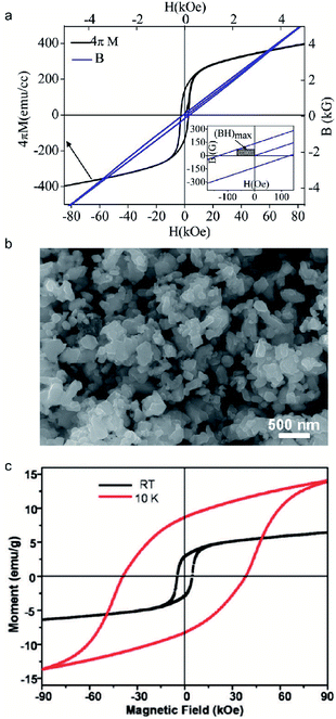 |
| | Fig. 8 (a) Magnetic characteristics of Fe3Se4 nanocrystals at 300 K. (Inset) Calculation of the maximum energy product of Fe3Se4; (b) typical SEM images of the as-synthesized Fe3Se4 nanoplatelets; (c) magnetic loops of faceted Fe3Se4 nanoparticles measured with a field of 90 kOe at 10 K and room temperature. Reproduced from ref. 88, 91 and 92 with the permission of American Chemical Society. | |
3 Conclusions
An overview of the existing and advanced manufacturing routes, developed in the past few decades, was explored and reviewed for rare-earth-free iron-based permanent magnets. The utility of versatile properties of iron-based magnets, such as coercivity and energy product, promotes the development of several permanent magnet candidates such as FePd, FePt, FeCo, Fe16N2, ε-Fe2O3, FeNi and Fe3Se4. Among the prepared FeCo phase, the optimal estimated energy product and coercivity achieved are 66 MGOe and 188 kOe. For FePd alloys, the maximum coercivity of 2.6 kOe and saturation magnetization of 190 emu g−1 showed the advantages of exchange-coupling. Meanwhile, the eutectic crystallization method indicated an advanced route to minimize the manufacturing procedure. The FePt magnet showed an optimal coercivity of 7.6 kOe with an optimum energy product of 5.0 MGOe. The Fe16N2 magnet presented a high coercivity of 1910 Oe and energy product of 20 MGOe. The coercivity of ε-Fe2O3 prepared in a silica template can be tunable from 31 kOe to 45 kOe. The rare-earth-free magnets, synthesized using iron-based precursors, play an important role in developing permanent magnets. The basic magnetic properties, such as coercivity and energy product, have been widely developed in several iron-based magnetic materials due to iron’s low cost and abundance nature. However, the limitation of low energy product of rare-earth-free Fe-based magnets still poses a significant challenge for its practical applications, while the tunable magnetic properties achieved by doping could be a promising strategy to further improve their energy product. Therefore, the trend of permanent magnet development would focus on high magnetic performance in the foreseeable future accompanied by the extension of materials list.
Conflicts of interest
There are no conflicts to declare.
Acknowledgements
S. R. acknowledges the support from the U.S. National Science Foundation (NSF) under the CAREER Award No. NSF-DMR-1830749.
Notes and references
- S. J. Galioto, P. B. Reddy, A. M. El-Refaie and J. P. Alexander, IEEE Trans. Ind. Appl., 2014, 51, 2148–2160 Search PubMed.
- M. Ghidini, R. Pellicelli, J. Prieto, X. Moya, J. Soussi, J. Briscoe, S. Dunn and N. Mathur, Nat. Commun., 2013, 4, 1–7 Search PubMed.
- S. Morimoto, Y. Tong, Y. Takeda and T. Hirasa, IEEE Trans. Ind. Electron., 1994, 41, 511–517 CrossRef.
- M. Haavisto and M. Paju, IEEE Trans. Magn., 2009, 45, 5277–5280 CAS.
-
L. Chen, J. Wang, P. Lazari and X. Chen, Optimizations of a permanent magnet machine targeting different driving cycles for electric vehicles, 2013 International Electric Machines & Drives, IEEE, 2013, pp. 855–862 Search PubMed.
-
C. Stoeckert, Wind turbine driven generator to recharge batteries in electric vehicles, US Pat., US3876925A, 1975.
- L. Zhu and J. Zhao, Appl. Phys. A: Mater. Sci. Process., 2013, 111, 379–387 CrossRef CAS.
- J. Coey, J. Magn. Magn. Mater., 2002, 248, 441–456 CrossRef CAS.
- H. Kirchmayr, J. Phys. D: Appl. Phys., 1996, 29, 2763 CrossRef CAS.
- D. McDonald, IEEE Trans. Magn., 1986, 22, 1075–1077 CrossRef.
- H. Nakamura, Scr. Mater., 2018, 154, 273–276 CrossRef CAS.
- K. Skokov and O. Gutfleisch, Scr. Mater., 2018, 154, 289–294 CrossRef CAS.
-
M. H. Ghandehari, Rare earth-iron-boron-permanent magnets, US Pat., US4952252A, 1990.
- E. W. Blackmore, IEEE Trans. Nucl. Sci., 1985, 32, 3669–3671 Search PubMed.
- D. Lee, S. Bauser, A. Higgins, C. Chen, S. Liu, M. Huang, Y. Peng and D. Laughlin, J. Appl. Phys., 2006, 99, 08B516 CrossRef.
- J. Cui, M. Kramer, L. Zhou, F. Liu, A. Gabay, G. Hadjipanayis, B. Balasubramanian and D. Sellmyer, Acta Mater., 2018, 158, 118–137 CrossRef CAS.
- E. Alonso, A. M. Sherman, T. J. Wallington, M. P. Everson, F. R. Field, R. Roth and R. E. Kirchain, Environ. Sci. Technol., 2012, 46, 3406–3414 CrossRef CAS PubMed.
- L. H. Lewis and F. Jiménez-Villacorta, Metall. Mater. Trans. A, 2013, 44, 2–20 CrossRef CAS.
- Y. Jiang, M. Al Mehedi, E. Fu, Y. Wang, L. F. Allard and J.-P. Wang, Sci. Rep., 2016, 6, 25436 CrossRef CAS PubMed.
- M. Averbuch-Pouchot, R. Chevalier, J. Deportes, B. Kebe and R. Lemaire, J. Magn. Magn. Mater., 1987, 68, 190–196 CrossRef CAS.
- Y. Sun, J. Zhao, Z. Liu, W. Xia, S. Zhu, D. Lee and A. Yan, J. Magn. Magn. Mater., 2015, 379, 58–62 CrossRef CAS.
- N. Kleinerman, V. Serikov, N. Vlasova and A. Popov, Philos. Mag., 2018, 98, 2380–2396 CrossRef CAS.
- S. Okamoto, T. Shinozaki, T. Yamashita, N. Kikuchi and O. Kitakami, J. Magn. Soc. Jpn., 2009, 33, 451–454 CrossRef CAS.
- J. Liu, G. Guo, X. Zhang, F. Zhang, B. Ma and J.-P. Wang, Acta Mater., 2020, 184, 143–150 CrossRef CAS.
- M. Mohapatra and S. Anand, Int. J. Eng. Sci. Technol., 2010, 2, 127–146 Search PubMed.
- A. Figuerola, R. Di Corato, L. Manna and T. Pellegrino, Pharmacol. Res., 2010, 62, 126–143 CrossRef CAS PubMed.
- V. Brabers, Phys. Status Solidi B, 1969, 33, 563–572 CrossRef CAS.
-
R. Skomski, in Novel Functional Magnetic Materials, Springer, 2016, pp. 359–395 Search PubMed.
- C. Bean and D. Rodbell, Phys. Rev., 1962, 126, 104 CrossRef CAS.
- D. S. Mathew and R.-S. Juang, Chem. Eng. J., 2007, 129, 51–65 CrossRef CAS.
- D. Bahadur, S. Rajakumar and A. Kumar, J. Chem. Sci., 2006, 118, 15–21 CrossRef CAS.
- M. A. Willard, Y. Nakamura, D. E. Laughlin and M. E. McHenry, J. Am. Ceram. Soc., 1999, 82, 3342–3346 CrossRef CAS.
- R. Boll and H. Warlimont, IEEE Trans. Magn., 1981, 17, 3053–3058 CrossRef.
- L. M. Rossi, N. J. Costa, F. P. Silva and R. Wojcieszak, Green Chem., 2014, 16, 2906–2933 RSC.
- K. Maaz, A. Mumtaz, S. Hasanain and A. Ceylan, J. Magn. Magn. Mater., 2007, 308, 289–295 CrossRef CAS.
- X. Zhao, C.-Z. Wang, Y. Yao and K.-M. Ho, Phys. Rev. B, 2016, 94, 224424 CrossRef.
- S. Okamoto, O. Kitakami and Y. Shimada, J. Appl. Phys., 1996, 79, 5250–5252 CrossRef CAS.
-
S. Ren and J. Yang, Magnetic Nanomaterials: Fundamentals, Synthesis and Applications, 2017 Search PubMed.
- G. Vashisht, R. Goyal, M. Bala, S. Ojha and S. Annapoorni, IEEE Trans. Magn., 2018, 55, 1–5 Search PubMed.
-
N. H. Goo, Formation of hard magnetic L10-FePt/FePd monolayers from elemental multilayers, PhD thesis, University of Stuttgart, 2007.
- E. Poirier, F. E. Pinkerton, R. Kubic, R. K. Mishra, N. Bordeaux, A. Mubarok, L. H. Lewis, J. I. Goldstein, R. Skomski and K. Barmak, J. Appl. Phys., 2015, 117, 17E318 CrossRef.
- N. Vlasova, A. Popov, N. Kleinerman, V. Serikov, V. Gaviko and L. Stashkova, Philos. Mag., 2019, 99, 2198–2219 CrossRef CAS.
-
A. A. El Gendy, J. M. Barandiaran and R. L. Hadimani, Magnetic Nanostructured Materials From Lab to Fab, Elsevier, 2018 Search PubMed.
- Y. Jin, W. Zhang, P. R. Kharel, S. R. Valloppilly, R. Skomski and D. J. Sellmyer, AIP Adv., 2016, 6, 056002 CrossRef PubMed.
- C. Chinnasamy, M. M. Jasinski, A. Ulmer, W. Li, G. Hadjipanayis and J. Liu, IEEE Trans. Magn., 2012, 48, 3641–3643 CAS.
- X. Guo, Z. Altounian and J. Ström-Olsen, J. Appl. Phys., 1991, 69, 6067–6069 CrossRef CAS.
- P. Manchanda, P. Kumar, A. Kashyap, M. Lucis, J. E. Shield, A. Mubarok, J. Goldstein, S. Constantinides, K. Barmak and L. Lewis, IEEE Trans. Magn., 2013, 49, 5194–5198 CAS.
- H. Fang, S. Kontos, J. Ångström, J. Cedervall, P. Svedlindh, K. Gunnarsson and M. Sahlberg, J. Solid State Chem., 2016, 237, 300–306 CrossRef CAS.
- L. Zhou, M. K. Miller, P. Lu, L. Ke, R. Skomski, H. Dillon, Q. Xing, A. Palasyuk, M. McCartney and D. Smith, Acta Mater., 2014, 74, 224–233 CrossRef CAS.
- R. Skomski and D. Sellmyer, J. Rare Earths, 2009, 27, 675–679 CrossRef.
- S. Tumanski, Organ, 2010, 4, 10 Search PubMed.
- A. López-Ortega, M. Estrader, G. Salazar-Alvarez, A. G. Roca and J. Nogués, Phys. Rep., 2015, 553, 1–32 CrossRef.
- J. Coey, IEEE Trans. Magn., 2011, 47, 4671–4681 CAS.
-
J. M. Coey, Magnetism and Magnetic Materials, Cambridge university press, 2010 Search PubMed.
- J. Kim, Y. Lee and S. Sun, J. Am. Chem. Soc., 2010, 132, 4996–4997 CrossRef CAS PubMed.
- T. Osaka, M. Takai, K. Hayashi, K. Ohashi, M. Saito and K. Yamada, Nature, 1998, 392, 796–798 CrossRef CAS.
- D. Wu, Q. Zhang, J. P. Liu, D. Yuan and R. Wu, Appl. Phys. Lett., 2008, 92, 052503 CrossRef.
- A. Winkelmann, M. Przybylski, F. Luo, Y. Shi and J. Barthel, Phys. Rev. Lett., 2006, 96, 257205 CrossRef PubMed.
- P. Warnicke, G. Andersson, M. Björck, J. Ferré and P. Nordblad, J. Phys.: Condens. Matter, 2007, 19, 226218 CrossRef.
- D. Kim and J. Hong, Surf. Sci., 2012, 606, 1960–1964 CrossRef CAS.
- G. Giannopoulos, L. Reichel, A. Markou, I. Panagiotopoulos, V. Psycharis, C. Damm, S. Fähler, I. Khan, J. Hong and D. Niarchos, J. Appl. Phys., 2015, 117, 223909 CrossRef.
- I. Khan and J. Hong, J. Phys. D: Appl. Phys., 2014, 47, 415002 CrossRef.
- M. Gong, A. Kirkeminde, M. Wuttig and S. Ren, Nano Lett., 2014, 14, 6493–6498 CrossRef CAS PubMed.
- L. Wu, A. Mendoza-Garcia, Q. Li and S. Sun, Chem. Rev., 2016, 116, 10473–10512 CrossRef CAS PubMed.
- K. Tanaka, T. Ichitsubo and M. Koiwa, Mater. Sci. Eng., A, 2001, 312, 118–127 CrossRef.
- A. Kirkeminde and S. Ren, Nano Lett., 2014, 14, 4493–4498 CrossRef CAS PubMed.
-
J. Liu, in Nanoscale Magnetic Materials and Applications, Springer, 2009, pp. 309–335 Search PubMed.
- M. Chen and D. E. Nikles, J. Appl. Phys., 2002, 91, 8477–8479 CrossRef CAS.
- K. Sato and Y. Hirotsu, Mater. Trans., 2006, 47, 59–62 CrossRef CAS.
- K. Sato, B. Bian and Y. Hirotsu, Jpn. J. Appl. Phys., 2000, 39, L1121 CrossRef CAS.
- K. Watanabe, H. Kura and T. Sato, Sci. Technol. Adv. Mater., 2006, 7, 145 CrossRef CAS.
- Y. Hou, H. Kondoh, T. Kogure and T. Ohta, Chem. Mater., 2004, 16, 5149–5152 CrossRef CAS.
- Y. Yu, K. Sun, Y. Tian, X.-Z. Li, M. J. Kramer, D. J. Sellmyer, J. E. Shield and S. Sun, Nano Lett., 2013, 13, 4975–4979 CrossRef CAS PubMed.
- Z. Shao, L. An, Z. Li, Y. Huang, Y. Hu and S. Ren, Chem. Commun., 2020, 6555–6558 RSC.
-
M. J. Bonder, Y. Huang and G. C. Hadjipanayis, in Advanced Magnetic Nanostructures, Springer, 2006, pp. 183–206 Search PubMed.
- L. Graf and A. Kussmann, Z. Phys., 1935, 36, 544–551 CAS.
- B. Jeyadevan, K. Urakawa, A. Hobo, N. Chinnasamy, K. Shinoda, K. Tohji, D. D. J. Djayaprawira, M. Tsunoda and M. Takahashi, Jpn. J. Appl. Phys., 2003, 42, L350 CrossRef CAS.
- S. Sun, C. B. Murray, D. Weller, L. Folks and A. Moser, science, 2000, 287, 1989–1992 CrossRef CAS PubMed.
- S. Sun, S. Anders, T. Thomson, J. Baglin, M. F. Toney, H. F. Hamann, C. Murray and B. D. Terris, J. Phys. Chem. B, 2003, 107, 5419–5425 CrossRef CAS.
- M. Chen, J. Liu and S. Sun, J. Am. Chem. Soc., 2004, 126, 8394–8395 CrossRef CAS PubMed.
- J. Zhang, C. Li, J. Armstrong and S. Ren, Chem. Commun., 2019, 55, 656–658 RSC.
- T. Ogawa, Y. Ogata, R. Gallage, N. Kobayashi, N. Hayashi, Y. Kusano, S. Yamamoto, K. Kohara, M. Doi and M. Takano, Appl. Phys. Express, 2013, 6, 073007 CrossRef.
- K. Jack, J. Alloys Compd., 1995, 222, 160–166 CrossRef CAS.
- T. Kim and M. Takahashi, Appl. Phys. Lett., 1972, 20, 492–494 CrossRef CAS.
- X. Bao, R. M. Metzger and M. Carbucicchio, J. Appl. Phys., 1994, 75, 5870–5872 CrossRef CAS.
- Y. Jiang, J. Liu, P. K. Suri, G. Kennedy, N. N. Thadhani, D. J. Flannigan and J. P. Wang, Adv. Eng. Mater., 2016, 18, 1009–1016 CrossRef CAS.
- A. Sivkov, E. Naiden, A. Ivashutenko and I. Shanenkov, J. Magn. Magn. Mater., 2016, 405, 158–168 CrossRef CAS.
- J. Sans, V. Monteseguro, G. Garbarino, M. Gich, V. Cerantola, V. Cuartero, M. Monte, T. Irifune, A. Muñoz and C. Popescu, Nat. Commun., 2018, 9, 1–11 CrossRef CAS PubMed.
- B. Wang, J. S. Chen, H. B. Wu, Z. Wang and X. W. Lou, J. Am. Chem. Soc., 2011, 133, 17146–17148 CrossRef CAS PubMed.
- J. Jin, S. i. Ohkoshi and K. Hashimoto, Adv. Mater., 2004, 16, 48–51 CrossRef CAS.
- S. Sakurai, K. Tomita, K. Hashimoto, H. Yashiro and S.-i. Ohkoshi, J. Phys. Chem. C, 2008, 112, 20212–20216 CrossRef CAS.
- A. Namai, M. Yoshikiyo, K. Yamada, S. Sakurai, T. Goto, T. Yoshida, T. Miyazaki, M. Nakajima, T. Suemoto and H. Tokoro, Nat. Commun., 2012, 3, 1–6 Search PubMed.
- J. Kohout, P. Brázda, K. Závěta, D. Kubániová, T. Kmječ, L. Kubíčková, M. Klementová, E. Šantavá and A. Lančok, J. Appl. Phys., 2015, 117, 17D505 CrossRef.
- S.-i. Ohkoshi, K. Imoto, A. Namai, S. Anan, M. Yoshikiyo and H. Tokoro, J. Am. Chem. Soc., 2017, 139, 13268–13271 CrossRef CAS PubMed.
- M. Kotsugi, C. Mitsumata, H. Maruyama, T. Wakita, T. Taniuchi, K. Ono, M. Suzuki, N. Kawamura, N. Ishimatsu and M. Oshima, Appl. Phys. Express, 2009, 3, 013001 CrossRef.
- J. Pauleve, D. Dautreppe, J. Laugier and L. Néel, J. Phys. Radium, 1962, 23, 841–843 CrossRef CAS.
- K. Reuter, D. B. Williams and J. Goldstein, Metall. Trans. A, 1989, 20, 711–718 CrossRef.
- T. Kojima, M. Mizuguchi, T. Koganezawa, K. Osaka, M. Kotsugi and K. Takanashi, Jpn. J. Appl. Phys., 2011, 51, 010204 Search PubMed.
-
J. Mohapatra and J. P. Liu, in Handbook of Magnetic Materials, Elsevier, 2018, vol. 27, pp. 1–57 Search PubMed.
- A. Montes-Arango, L. Marshall, A. D. Fortes, N. Bordeaux, S. Langridge, K. Barmak and L. Lewis, Acta Mater., 2016, 116, 263–269 CrossRef CAS.
- Y. Hayashi, S. Gotou, M. Mizuguchi, M. Kotsugi, Y. Kitou, E. Okuno and K. Takanashi, J. Magn. Soc. Jpn., 2013, 37, 198–201 CrossRef CAS.
- M. Gong and S. Ren, Chem. Mater., 2015, 27, 7795–7800 CrossRef CAS.
- M. Sen Bishwas, R. Das and P. Poddar, J. Phys. Chem. C, 2014, 118, 4016–4022 CrossRef CAS.
- K. Hirakawa, J. Phys. Soc. Jpn., 1957, 12, 929–938 CrossRef CAS.
- D. Li, D. Pan, S. Li and Z. Zhang, Sci. China: Phys., Mech. Astron., 2016, 59, 617501 Search PubMed.
- H. Zhang, G. Long, D. Li, R. Sabirianov and H. Zeng, Chem. Mater., 2011, 23, 3769–3774 CrossRef CAS.
- G. Long, H. Zhang, D. Li, R. Sabirianov, Z. Zhang and H. Zeng, Appl. Phys. Lett., 2011, 99, 202103 CrossRef.
- D. Li, Y. Li, D. Pan, Z. Zhang and C.-J. Choi, J. Magn. Magn. Mater., 2019, 469, 535–544 CrossRef CAS.
|
| This journal is © The Royal Society of Chemistry 2020 |
 Open Access Article
 *abc
*abc


![[thin space (1/6-em)]](https://www.rsc.org/images/entities/char_2009.gif) 000 years at 573 K,98 L10-FeNi is only found naturally in meteorites.99 In 2015, Poirier et al. introduced tetragonal L10-FeNi obtained from the meteorite NWA 6259, presenting a large anisotropy field of 14.4 kOe (Fig. 7a).41 Furthermore, in 2016 Lewis et al. reported tetragonal FeNi that was generated through an annealing protocol and pointed out the crystal structure transition of the FeNi lattice from a cubic to tetragonal unit cell, as shown in Fig. 7b.100 Meanwhile, the chemical synthesis of L10-FeNi was also presented by Hayashi et al. in 2013. The L10-FeNi alloy, prepared by a reductive reaction, showed a maximum coercivity of 220 kA m−1 (2765 Oe).101 However, the stabilization of tetragonal FeNi alloys is a challenging task. In order to overcome this challenge, Ren introduced a rational epitaxial core/shell design to stabilize tetragonal FeNi nanocrystals (Fig. 7c). The reconstruction of tetragonal FeNi was triggered by the surface stress due to the existence of AuCu cores, as shown in Fig. 7d. The designed FeNi exhibited a large coercivity of 1010.2 Oe and a saturation magnetization of 122 emu g−1, as shown in Fig. 7e.102
000 years at 573 K,98 L10-FeNi is only found naturally in meteorites.99 In 2015, Poirier et al. introduced tetragonal L10-FeNi obtained from the meteorite NWA 6259, presenting a large anisotropy field of 14.4 kOe (Fig. 7a).41 Furthermore, in 2016 Lewis et al. reported tetragonal FeNi that was generated through an annealing protocol and pointed out the crystal structure transition of the FeNi lattice from a cubic to tetragonal unit cell, as shown in Fig. 7b.100 Meanwhile, the chemical synthesis of L10-FeNi was also presented by Hayashi et al. in 2013. The L10-FeNi alloy, prepared by a reductive reaction, showed a maximum coercivity of 220 kA m−1 (2765 Oe).101 However, the stabilization of tetragonal FeNi alloys is a challenging task. In order to overcome this challenge, Ren introduced a rational epitaxial core/shell design to stabilize tetragonal FeNi nanocrystals (Fig. 7c). The reconstruction of tetragonal FeNi was triggered by the surface stress due to the existence of AuCu cores, as shown in Fig. 7d. The designed FeNi exhibited a large coercivity of 1010.2 Oe and a saturation magnetization of 122 emu g−1, as shown in Fig. 7e.102


