
 Open Access Article
 This Open Access Article is licensed under a Creative Commons Attribution-Non Commercial 3.0 Unported Licence
The MgB2-catalyzed growth of boron nitride nanotubes using B/MgO as a boron containing precursor
Dongfei
Zhang†
abcd,
Kai
Zhang†
bc,
Songfeng
E
cd,
Dapeng
Liu
cd,
Chaowei
Li
ce and
Yagang
Yao
 *bcd
*bcd
aNano Science and Technology Institute, University of Science and Technology of China, Suzhou 215123, China
bNational Laboratory of Solid State Microstructures, College of Engineering and Applied Sciences, Jiangsu Key Laboratory of Artificial Functional Materials, Collaborative Innovation Center of Advanced Microstructures, Nanjing University, Nanjing 210093, China. E-mail: ygyao2018@nju.edu.cn
cDivision of Advanced Nanomaterials, Key Laboratory of Nanodevices and Applications, Joint Key Laboratory of Functional Nanomaterials and Devices, CAS Center for Excellence in Nanoscience, Suzhou Institute of Nano-Tech and Nano-Bionics, Chinese Academy of Sciences, Suzhou 215123, China
dDivision of Nanomaterials and Jiangxi Key Lab of Carbonene Materials, Suzhou Institute of Nano-Tech and Nano-Bionics, Nanchang, Chinese Academy of Sciences, Nanchang 330200, China
eCollege of Chemistry and Chemical Engineering, Anyang Normal University, Anyang 455002, China
First published on 1st June 2020
Abstract
With the development of preparation technology, obtaining boron nitride nanotubes (BNNTs) is no longer difficult, but it is still not easy to balance the quality and purity of the obtained products using existing methods. In this work, we investigated a previously reported MgB2 catalyst to explore the synthesis of BNNTs at a higher temperature in a conventional chemical vapor deposition (CVD) system from a classic B/MgO precursor. Various characterization methods showed the high activity of MgB2 at 1400 °C and the superiority of the as-grown BNNTs in terms of purity and quality. Further reference experiments and element characterization measurements were also performed to verify the role of MgB2 in the growth of the BNNTs, finding that B/MgO/MgB2 is a simple and efficient precursor.
1. Introduction
Boron nitride nanotubes (BNNTs) as a structural analog to carbon nanotubes (CNTs), not only share their similar high strength, stiffness,1 thermal conductivity2–4 and low density,5 but also possess some unique properties. For example, strong resistance to oxidation,6,7 excellent electrical insulation,8 superhydrophobic ability,9 catalytic properties10 and biocompatibility11 and so on. However, development of their applications is far behind other low dimensional nanomaterials such as CNTs or graphene because it is challenging to produce high quality BNNTs.For the preparation of BNNTs, the early used methods were adjusted from methods used to produce CNTs, such as arc discharge,12 laser heating,13–15 inductive thermal plasma16 and floating catalyst chemical vapor deposition (CVD).17–19 Among them, the excessive high growth temperature/pressure (up to 5000 K/1.4 MPa) made the combination of boron and nitrogen extremely violent and difficult to control, resulting in serious contamination of the BNNTs.12,16,20–22 Furthermore, the corrosiveness, toxicity and explosiveness of the boron source used in the floating catalysis CVD had significant hidden dangers in terms of laboratory safety.17–19 The quality of the BNNTs obtained using template substitution was largely inherited from the original CNTs, and the residual carbons were difficult to remove.23 Some studies have also shown that the transition metal in the precursor did not participate in the formation of BNNTs in the ball-milling and thermal annealing method, and they were a product of the nitridation reaction rather than a catalyst reaction.24,25 In contrast to the methods described above, boron oxide chemical vapor deposition (BOCVD) used B/MgO as a highly efficient precursor to obtain BNNTs with a high quality and purity.26 However, the yield of the nanotubes was not satisfactory until Chunyi Zhi added FeO into the precursor.27 Meanwhile, Chee Huei Lee's team developed the growth vapor trapping approach to grow BNNTs in a conventional horizontal tube furnace,28 which proved that MgO, Ni or Fe might be the catalyst for BNNT growth.29
Our group had also been studying the efficient preparation and application of BNNTs for many years. We initially started with the BOCVD method, and selected B/MgO/Fe2O3 as the precursor to grow BNNTs30 and used ammonium tungstate as a promoter.31 However, these methods failed to meet our expectations. Therefore, we analyzed the reactions involved in the BOCVD process and the physicochemical properties of the related substances, believing that MgB2 was an efficient catalyst, BNNTs were found on the substrate whether it was directly added32 or synthesized in situ.33 Pervaiz Ahmad's team also found that MgB2 could not only act as the catalyst, but also directly react with NH3 and form BNNTs.34
We have confirmed that MgB2 can react with various boron sources and efficiently catalyze the growth of BNNTs, but the preparation conditions and catalytic mechanism have not been studied. In this paper, we directly introduced MgB2 as the catalyst to grow BNNTs with a high quality and purity from a B/MgO precursor in a conventional horizontal tubular furnace. The morphology, composition and structure of the as-grown BNNTs were thoroughly analyzed. Direct element characterization proved that MgB2 can still function as the catalyst at a higher temperature (1400 °C), and further reference experiments also show its indispensable role and the complementarities between MgB2/B/MgO.
2. Experimental
2.1 Materials
Boron was purchased from China New Metal Materials Technology Company Limited, MgO was purchased from Sinopharm Chemical Reagent Company Limited, and MgB2 was purchased from Sigma-Aldrich. All chemicals were of analytical grade and used as received, without further treatment. The high purity gases (99.999%, Ar, NH3) were purchased from the Linde Gas (China) Company Limited.2.2 Preparation of the BNNTs
The precursor used for the growth of the BNNTs was prepared in two steps. First, a certain amount of B and MgO (2![[thin space (1/6-em)]](https://www.rsc.org/images/entities/char_2009.gif) :1, molar ratio) was weighed and grounded. Then, a certain amount of grounded MgB2 was weighed and mixed with the previously obtained B/MgO powder to form the precursor (140 mg, B:MgO:MgB2 = 2:1:1.5, molar ratio) for BNNT growth. The BNNTs were synthesized in a horizontal tube furnace (Hefei Kejing Materials Technology Co., LTD, GSL-1700X) with a temperature zone of approximately 60 cm, consisting of an alumina tube that was 120 cm in length and 60 mm in diameter. Before heating, the alumina boat containing the precursor and a piece of clean Si/SiO2 substrate were placed in the center of the tube (Fig. 1a). Subsequently, the furnace temperature was maintained at 1400 °C for 2 h in 200 standard cubic centimeters per minute (sccm) NH3. After that, the system was cooled naturally to room temperature in Ar.
:1, molar ratio) was weighed and grounded. Then, a certain amount of grounded MgB2 was weighed and mixed with the previously obtained B/MgO powder to form the precursor (140 mg, B:MgO:MgB2 = 2:1:1.5, molar ratio) for BNNT growth. The BNNTs were synthesized in a horizontal tube furnace (Hefei Kejing Materials Technology Co., LTD, GSL-1700X) with a temperature zone of approximately 60 cm, consisting of an alumina tube that was 120 cm in length and 60 mm in diameter. Before heating, the alumina boat containing the precursor and a piece of clean Si/SiO2 substrate were placed in the center of the tube (Fig. 1a). Subsequently, the furnace temperature was maintained at 1400 °C for 2 h in 200 standard cubic centimeters per minute (sccm) NH3. After that, the system was cooled naturally to room temperature in Ar.
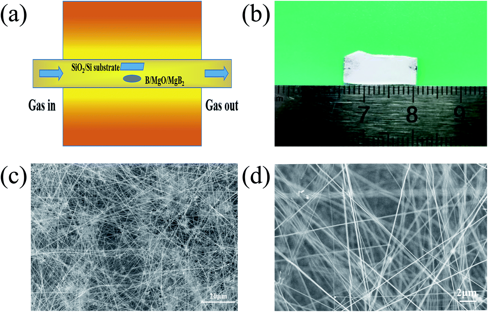 | ||
| Fig. 1 A schematic illustration of the experimental setup (a), and an optical image (b) and representative SEM images (c) and (d) of the BNNTs grown on the silicon substrate. | ||
2.3 Characterization
Scanning electron microscopy (SEM) images were obtained on a field-emission SEM (Hitachi S4800, Japan). Transmission electron microscopy (TEM) was performed on a Tecnai G2 F20S-TWIN with an operating voltage of 200 kV equipped using energy-dispersive X-ray spectroscopy (EDX). The X-ray diffraction information of the BNNTs was obtained by powder X-ray diffraction (XRD, D8 Advance) using Cu Kα radiation (45 kV and 40 mA). XRD data was collected at room temperature, using Cu-Kα (λ = 1.5418 Å) X-rays. The additional acquisition parameters were: 2θ range, 10–90°; scan rate, 0.02° s−1. Diffraction patterns were referenced against the JCPDS database for sample identification. Raman spectroscopy spectra were collected over the spectral range of 1000 to 2000 cm−1 using a LabRam ARAMIS Raman confocal microscope (Horiba HR800 Raman system) equipped with a 532 nm laser. The chemical nature of the prepared BNNTs were characterized using Fourier transform infrared spectroscopy (FTIR, Thermo Scientific Instruments, model NicoletiN10), and the spectroscopy of the BNNTs was measured at room temperature with a wave number range of 400 cm−1 to 4000 cm−1. The thermogravimetric analysis (TGA) measurements were performed on a Netzsch TG209 F1 under air, with a ramping rate of 10 °C min−1. The cathode luminescence (CL) spectroscopy of the BNNTs was carried out using a thermal field-emission electron microscope at room temperature (Quanta 400 FEG).3. Results
A schematic diagram of the experimental setup, optical and SEM images of the as-grown BNNTs deposited on Si/SiO2 substrate is shown in Fig. 1a. Under optimal conditions, the snow-white products completely cover the surface of the substrate, indicating the strong catalytic activity of MgB2 (Fig. 1b). For the convenience of taking photos, the substrate was moved from above the MgB2 catalyst and rotated 180°. SEM characterization was also used to examine the microstructure of the white products. As shown in Fig. 1c, no structure other than a large-area of dense and silky BNNTs was observed, showing the purity of the BNNTs, which is evidence of the effectiveness of our synthesis strategy. The lengths of these BNNTs were roughly estimated to be approximately 100 μm using the SEM image (Fig. 1d).The TEM images showed that the BNNTs possessed a long and straight tubular structure (Fig. 2a). Some dark spots that appeared on the wall of the nanotube (Fig. 2b) were a result of the internal double helix structure generated from the ionic bond interaction between the boron and nitrogen atoms,35,36 which had been observed in previous works.32 High resolution TEM images of a nanotube are presented in Fig. 2c and d, respectively. Fig. 2c shows that the nanotube is a multi-walled structure. The interplanar spacing of the wall was approximately 0.33 nm (Fig. 2d), which is characteristic of a d(002) spacing of h-BN.37 The spots in the selected area electron diffraction (SAED) pattern of the nanotube can be indexed as the (002) and (004) crystal plane of the h-BN layers (Fig. 2e). This confirmed the high crystal quality of the as-grown nanotubes. The EDX spectrum indicates the existence of BN (Fig. 2f). The strong peaks for B and N with a molar ratio of about 1:1 also confirm the nanotube composition and ratio of the as-grown BNNTs. The weak peaks observed for Cu, O, Mg and Si are a result of the copper mesh, MgO and MgB2 in the precursor and the scraped silicon substrate, respectively.
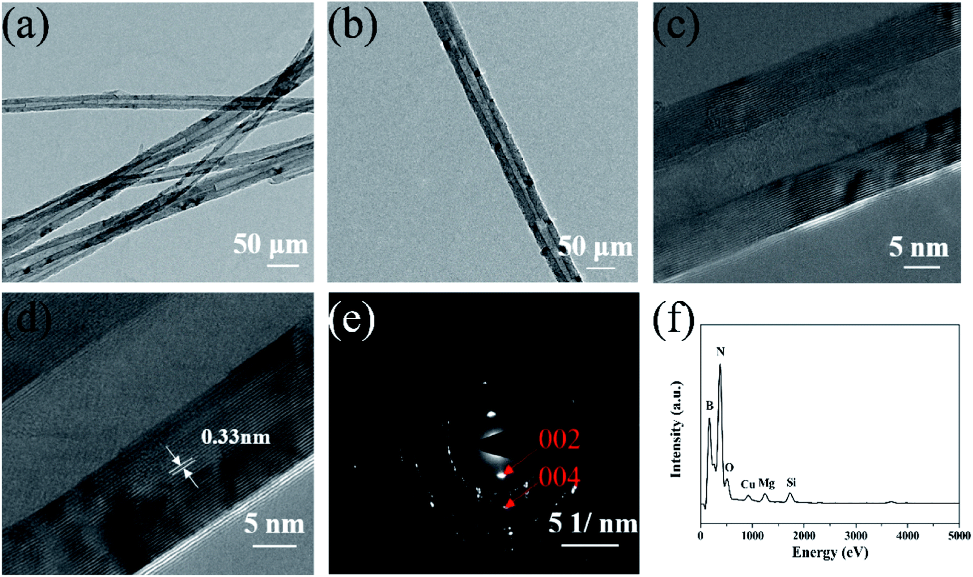 | ||
| Fig. 2 (a) and (b) Low magnification TEM images of the prepared BNNTs, (c) and (d) high magnification TEM images of an individual BNNT, and (e) and (f) SAED and EDX spectra of the prepared BNNTs. | ||
XRD characterization was also carried out on the BNNTs supported by the silicon substrate (Fig. 3a). The sharp and dominant peak at approximately 26.7° indicating an interplanar distance of 0.333 nm was indexed as the (002) crystal plane of h-BN (JCPDS card no.45-0896). The other characteristic peaks of h-BN at approximately 54.9° corresponded to the (004) crystal plane of the BNNTs. This was consistent with the TEM results (Fig. 2d and e). In addition to the reflections from h-BN, the peak at approximately 42.9° belonged to residual MgO (JCPDS card no.45-0916), and the weak peaks marked by “♥” belonged to Mg3B2O6 (JCPDS card no. 38-1475). These peaks can be further reduced by washing with dilute hydrochloric acid,38 then the obtained BNNTs would be purified.
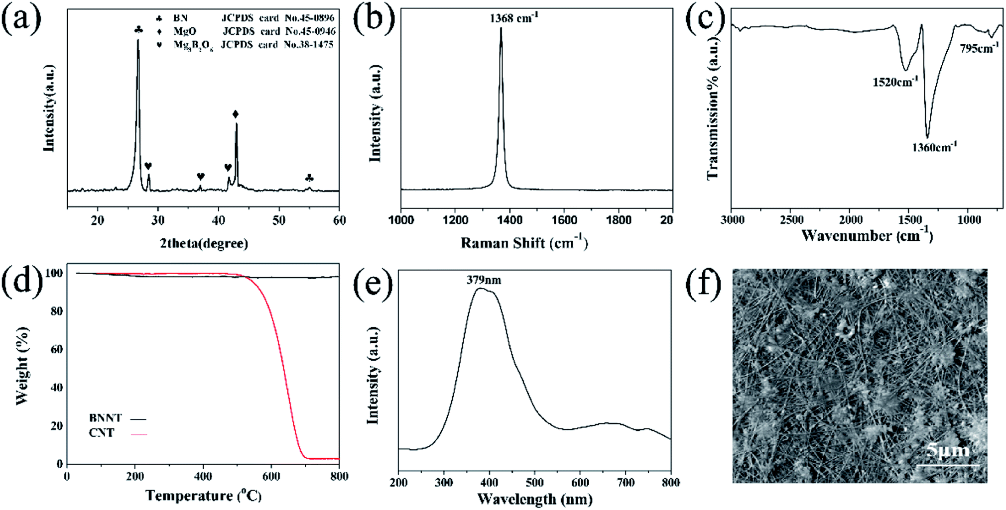 | ||
| Fig. 3 XRD (a), Raman (b), FTIR (c), TG (d) and CL (e) spectra of the prepared BNNTs, and (f) the SEM image of the BNNTs corresponding to (e). | ||
The Raman spectrum of the BNNTs is shown in Fig. 3b. The dominant peak located at 1368 cm−1 has a full width at half maximum (FWHM) value of approximately 15.9 cm−1. This peak was attributed to the truism E2g in-plane vibration mode of BN.39,40 Compared with the corresponding mode in the bulk h-BN41 (with an E2g of 1365 cm−1 and FWHM of ∼8 cm−1), the peak shown in Fig. 3b is broadened and has shifted to a higher wave number, but still showed a good crystallinity, which is consistent with above described TEM and XRD results.
Fourier transform infrared spectroscopy was also conducted to characterize the structure of the BNNTs (Fig. 3c). Three absorption frequency regimes were found at 1520, 1360 and 795 cm−1, respectively. The peak centered at 1520 cm−1 is Raman inactive, and is only revealed when the tube curvature induces a strain on the h-BN networks, which only exists in the spectrum of high purity BN crystals.28 The absorption bands at 1360 and 795 cm−1 are attributed to the in-plane stretching modes of the h-BN network.42–44 The strong peak at 1360 cm−1 is assigned to the B–N stretching vibration mode perpendicular to the c-axis. The weak absorption at 795 cm−1 is associated with the B–N–B bending vibration mode parallel to the c-axis.
Thermogravimetric analysis was further performed to elucidate the thermal stability of the BNNTs and compared with commercial CNTs (Fig. 3d). All of the samples were heated up to 800 °C at a rate of 10 °C min−1 in air. For BNNTs, almost no weight change was observed, indicating that the oxidation of the BNNTs had not yet taken place. On the other hand, the CNTs started to decompose at approximately 500 °C and were completely decomposed at 700 °C.
Based on the results described above, the BNNTs deposited on the silicon substrate were not only pure, but also had a high crystallinity, and the oxidation resistance in the air was also consistent with h-BN, showing that MgB2 is a highly efficient catalyst at a higher growth temperature.
The CL is the light emitted by a material under electron bombardment, which is a useful technique that can be used for characterization of the luminescence properties of nanostructures. Fig. 3e depicts a CL spectrum taken from the BNNTs under an accelerating voltage of 20 kV. The board UV band (∼379 nm) was attributed to the defect-related centers (B or N defect trapping sites) or intrinsic impurities in the nanotubes. The CL image recorded at approximately 379 nm indicates that the emissions came from the BNNTs45 (Fig. 3f). The CL result showed that the as-grown BNNTs catalyzed by MgB2 could be potentially applied to photovoltaic devices in the ultraviolet band.45
4. Discussion
In order to understand the mechanism of MgB2 catalyzing BNNT growth at a higher temperature (1400 °C), additional experiments were carried out. Firstly, only B/MgO was used as the precursor to grow BNNTs under a NH3 atmosphere. It was observed that only horn-like products were deposited on the silicon substrate (Fig. 4a), which are significantly different from the BNNTs observed in Fig. 1c and d. No BN peak appeared in the XRD pattern (Fig. 4b), and only a weak peak was observed in the Raman spectrum.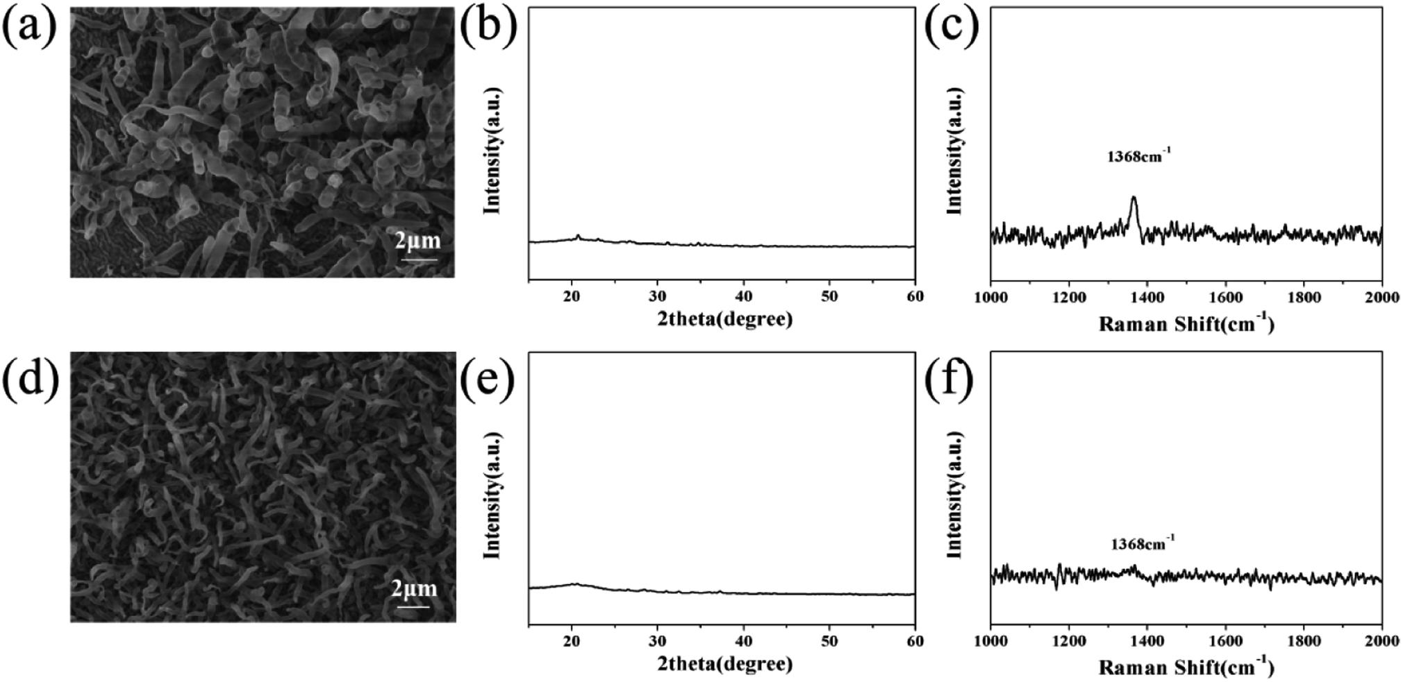 | ||
| Fig. 4 SEM images, and XRD and Raman spectra of the products obtained from B/MgO (a), (b) and (c) and MgO/MgB2 (d), (e) and (f), respectively. | ||
This may be because the melting points of B and MgO are 2180 °C and 2852 °C respectively, they are still solid at the growth temperature. The precursor powder only underwent simple grinding, the particle size of which is much larger than the nanoparticles required for nanotube growth.46 Namely, the physical properties and particle size of B and MgO do not meet the requirements of the vapor–liquid–solid (VLS) mechanism for catalysts. In addition, B and MgO can undergo side reactions generating borate with a higher melting point, and then leave the system (as Mg3B2O6 in Fig. 3a). A lack of MgB2 leads to the side reaction (forming borate), reducing the quality and quantity of the product. Meanwhile, MgB2 maintains a stable chemical structure and a liquid state at 800–1500 °C,47,48 the solubility of which is also suitable for gaseous BxOy and NH3,32 therefore it has the potential to catalyze the growth of the BNNTs.
Secondly, MgB2 contains boron, an experiment between MgB2 and MgO was conducted to verify whether it could be used as a boron precursor. The results of SEM, XRD and Raman were close to that of the reaction between B and MgO except for the size of the horn-like products (Fig. 4d) and the even weaker Raman peak (Fig. 4f). No clear diffraction peak was observed in the XRD pattern (Fig. 4e). This indicates that the three components, MgB2/B/MgO, in the precursor are indispensable for the growth of BNNTs.
Thirdly, EDX cross-section scans on the tip and middle of a BNNT were performed to further verify the role of MgB2. The elemental composition of the tip of the BNNT was different from that of other parts. In addition to the B and N that made up the BNNTs (Fig. 5c and d), a certain amount of Mg was also detected in the tip (Fig. 5a and c). Considering that MgB2 and BNNT both contain the boron element, this can be regarded as the existence of MgB2 in the tip of BNNTs, namely proof that the MgB2 nanoparticles catalyze the BNNT growth. The oxygen element in Fig. 5a originated from the decomposed boron source (BxOy), which was wrapped inside the nanotube before being detached from the MgB2 nanoparticles.
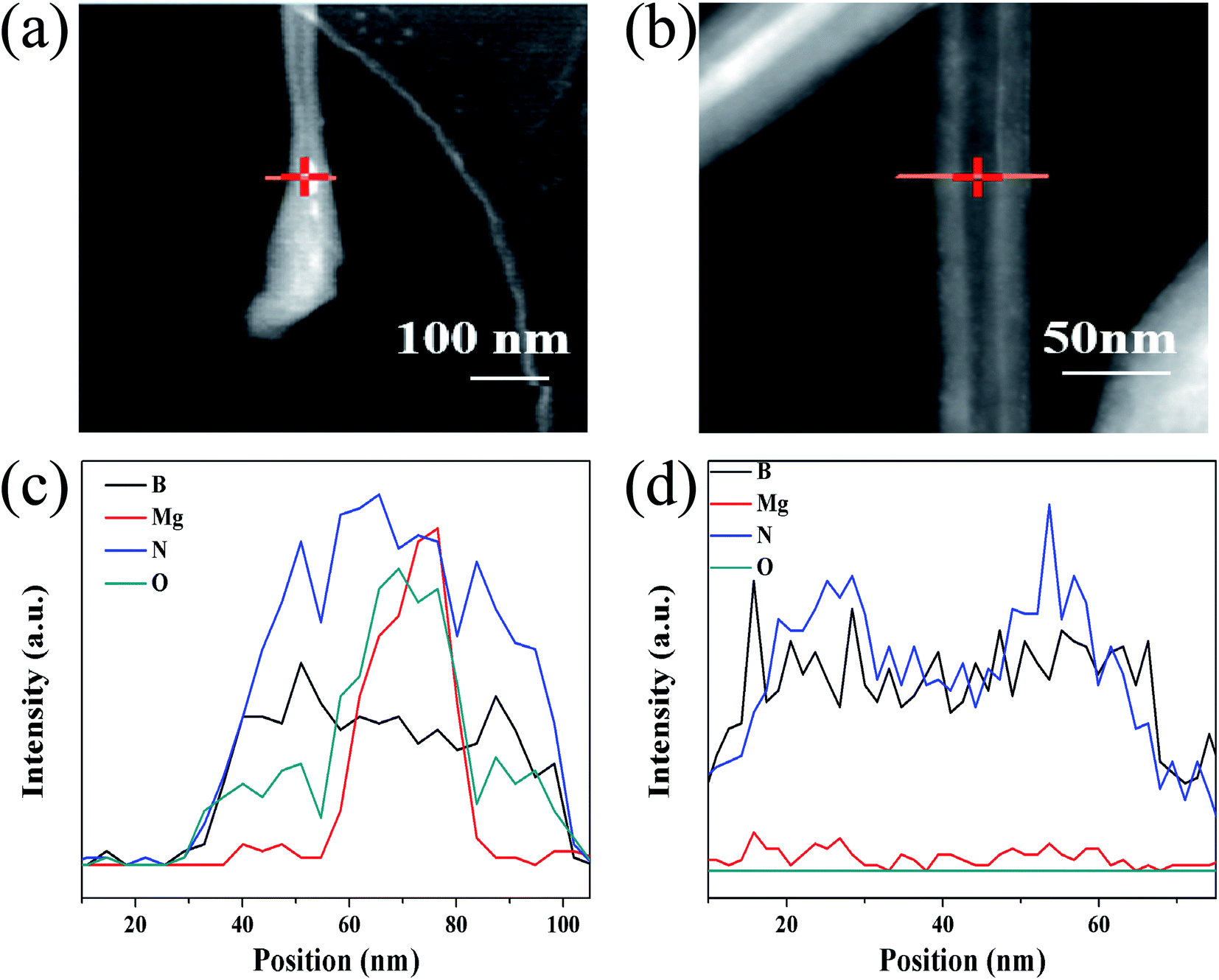 | ||
| Fig. 5 Line scanning EDX spectra of the tip (c) and center (d) of the prepared BNNTs and the corresponding TEM images (a) and (b). | ||
Taken together, the presence of MgB2 is indispensable to the growth of BNNT, and the nanoparticles were also detected in the tip of a nanotube. This not only showed that the growth of BNNT did indeed meet the VLS mechanism, but also the nanoparticles of MgB2 serve as an efficient catalyst. Separate experiments between the components also showed that the three components were interdependent, MgB2/B/MgO were indispensable for the growth of the BNNTs.
5. Conclusions
In summary, BNNTs with high quality and purity were grown using a MgB2 catalyst and a B/MgO boron-containing precursor in a conventional horizontal tube furnace. The purity of the nanotubes was characterized using optical microscopy, SEM, and FTIR studies. The quality of the BNNTs was verified using TEM, XRD, Raman, and TG analysis. The results from CL characterization showed the excellent UV emission performance of the as-grown BNNTs. Additional experiments explained the rationale for using the three components in B/MgO/MgB2 and the effects of MgB2 on the growth of BNNTs. Elemental characterization on the tip of a BNNT further detected the presence of a MgB2 nanoparticle, proving that MgB2 is still an efficient catalyst at 1400 °C.Conflicts of interest
There are no conflicts to declare.Acknowledgements
This work was supported by the National Key R&D Program of China (No. 2017YFB0406000), the National Natural Science Foundation of China (No. 51972162 and 51703241), the Science and Technology Project of Nanchang (2017-SJSYS-008), and the Postdoctoral Foundation of Jiangsu Province, China (No. 2019Z202, 2019Z203 and 2019K001).References
- B. Akdim, R. Pachter, X. Duan and W. W. Adams, Phys. Rev. B: Condens. Matter Mater. Phys., 2003, 67, 245404 CrossRef.
- T. Terao, C. Zhi and Y. Bando, J. Phys. Chem., 2010, 114, 4340–4344 CrossRef CAS PubMed.
- C. Zhi, Y. Xu and Y. Bando, ACS Nano, 2011, 5, 6571–6577 CrossRef CAS PubMed.
- T. Terao, Y. Bando and M. Mitome, J. Phys. Chem., 2009, 113, 13605–13609 CAS.
- D. Golberg, Y. Bando and Y. Huang, ACS Nano, 2010, 4, 2979–2993 CrossRef CAS PubMed.
- L. H. Li, J. Cervenka and K. Watanabe, ACS Nano, 2014, 8, 1457–1462 CrossRef CAS PubMed.
- Y. Chen, J. Zou, S. J. Campbell and G. Le Caer, Appl. Phys. Lett., 2004, 84, 2430–2432 CrossRef CAS.
- X. Blase, A. Rubio and S. Louie, Europhys. Lett., 1994, 28, 335–340 CrossRef CAS.
- L. B. Boinovich, A. M. Emelyanenko, A. S. Pashinin, C. H. Lee, J. Drelich and Y. K. Yap, Langmuir, 2012, 28, 1206–1216 CrossRef CAS PubMed.
- J. T. Grant, C. A. Carrero, F. Goeltl, J. Venegas, P. Mueller, S. P. Burt, S. E. Specht, W. P. McDermott, A. Chieregato and I. Hermans, Science, 2016, 354, 1570–1573 CrossRef CAS PubMed.
- A. Salvetti, L. Rossi and P. Iacopetti, Nanomedicine, 2015, 10, 1911–1922 CrossRef CAS PubMed.
- A. Loiseau, F. Willaime and N. Demoncy, Phys. Rev. Lett., 1996, 76, 4737–4740 CrossRef CAS PubMed.
- D. Golberg, Y. Bando, M. Eremets, K. Takemura, K. Kurashima and H. Yusa, Appl. Phys. Lett., 1996, 69, 2045–2047 CrossRef CAS.
- O. A. Louchev, Appl. Phys. Lett., 1997, 71, 3522–3524 CrossRef CAS.
- R. Arenal, O. Stephan and J.-L. Cochon, J. Am. Chem. Soc., 2007, 129, 16183–16189 CrossRef CAS PubMed.
- A. Fathalizadeh, T. Pham, W. Mickelson and A. Zettl, Nano Lett., 2014, 14, 4881–4886 CrossRef CAS PubMed.
- R. Ma, Y. Bando and T. Sato, Chem. Mater., 2001, 13, 2965–2971 CrossRef CAS.
- S. Chatterjee, M. J. Kim, D. N. Zakharov, S. M. Kim, E. A. Stach, B. Maruyama and L. G. Sneddon, Chem. Mater., 2012, 24, 2872–2879 CrossRef CAS.
- M. J. Kim, S. Chatterjee and S. M. Kim, Nano Lett., 2008, 8, 3298–3302 CrossRef CAS PubMed.
- K. S. Kim, C. T. Kingston and A. Hrdina, ACS Nano, 2014, 8, 6211–6220 CrossRef CAS PubMed.
- K. S. Kim, M. Couillard, H. Shin, M. Plunkett, D. Ruth, C. T. Kingston and B. Simard, ACS Nano, 2018, 12, 884–893 CrossRef CAS PubMed.
- V. G. Naumov, F. K. Kosyrev, V. G. Vostrikov, N. R. Arutyunyan, E. D. Obraztsova, V. I. Konov, H. Jiang, A. Nasibulin and E. Kauppinen, Laser Phys., 2009, 19, 1198–1200 CrossRef CAS.
- W. Han, Y. Bando, K. Kurashima and T. Sato, Appl. Phys. Lett., 1998, 73, 3085–3087 CrossRef CAS.
- Y. Chen, L. T. Chadderton, J. F. Gerald and J. S. Williams, Appl. Phys. Lett., 1999, 74, 2960–2962 CrossRef CAS.
- J. Kim, S. Lee, Y. R. Uhm, J. Jun, C. K. Rhee and G. M. Kim, Acta Mater., 2011, 59, 2807–2813 CrossRef CAS.
- C. Tang, Y. Bando, T. Sato and K. Kurashima, Chem. Commun., 2002, 1290–1291, 10.1039/b202177c.
- C. Zhi, Y. Bando, C. Tan and D. Golberg, Solid State Commun., 2005, 135, 67–70 CrossRef CAS.
- C. H. Lee, J. Wang, V. K. Kayatsha, J. Y. Huang and Y. K. Yap, Nanotechnology, 2008, 19, 455605 CrossRef PubMed.
- C. H. Lee, M. Xie, V. Kayastha, J. Wang and Y. K. Yap, Chem. Mater., 2010, 22, 1782–1787 CrossRef CAS.
- L. Wang, T. Li, L. Ling, J. Luo, K. Zhang, Y. Xu, H. Lu and Y. Yao, Chem. Phys. Lett., 2016, 652, 27–31 CrossRef CAS.
- S. E, C. Li, T. Li, R. Geng, Q. Li, W. Lu and Y. Yao, Nanotechnology, 2018, 29, 195604 CrossRef PubMed.
- S. E, L. Wu, C. Li, Z. Zhu, X. Long, R. Geng, J. Zhang, Z. Li, W. Lu and Y. Yao, Nanoscale, 2018, 10, 13895–13901 RSC.
- C. Li, X. Long and S. E, Nanoscale, 2019, 11, 11457–11463 RSC.
- P. Ahmad, M. U. Khandaker, N. Muhammad, F. Rehman, G. Khan, A. S. Khan, Z. Ullah, M. A. Rehman, S. Ahmed, M. Gulzar, I. U. Din, S. M. Ahmed, H. Ali and N. Arshid, Mater. Res. Bull., 2018, 98, 235–239 CrossRef CAS.
- C. Zhi, Y. Bando, C. Tang and D. Golberg, Mater. Sci. Eng. R Rep., 2010, 70, 92–111 CrossRef.
- A. Celik-Aktas, J. M. Zuo, J. F. Stubbins, C. Tang and Y. Bando, Acta Crystallogr. A, 2005, 61, 533–541 CrossRef PubMed.
- S. M. Kim, A. Hsu, M. H. Park, S. H. Chae, S. J. Yun, J. S. Lee, D. H. Cho, W. Fang, C. Lee, T. Palacios, M. Dresselhaus, K. K. Kim, Y. H. Lee and J. Kong, Nat. Commun., 2015, 6, 8662 CrossRef CAS PubMed.
- C. Li, X. Long, S. E, Q. Zhang, T. Li, J. Wu and Y. Yao, Nanoscale, 2019, 11, 11457–11463 RSC.
- D. M. Hoffman, G. L. Doll and P. C. Eklund, Phys. Rev. B: Condens. Matter Mater. Phys., 1984, 30, 6051–6056 CrossRef CAS.
- R. J. Nemanich, S. A. Solin and R. M. Martin, Phys. Rev. B: Condens. Matter Mater. Phys., 1981, 23, 6348–6356 CrossRef CAS.
- L. Song, L. Ci, H. Lu, P. B. Sorokin, C. Jin, J. Ni, A. G. Kvashnin, D. G. Kvashnin, J. Lou, B. I. Yakobson and P. M. Ajayan, Nano Lett., 2010, 10, 3209–3215 CrossRef CAS PubMed.
- E. Borowiak-Palen, T. Pichler, G. G. Fuentes, B. Bendjemil, X. Liu, A. Graff, G. Behr, R. J. Kalenczuk, M. Knupfer and J. Fink, Chem. Commun., 2003, 82–83, 10.1039/b208214d.
- Z. G. Chen, J. Zou and G. Liu, ACS Nano, 2008, 2, 2183–2191 CrossRef CAS PubMed.
- S. Xu, Y. Fan, J. Luo, L. Zhang, W. Wang, B. Yao and L. An, Appl. Phys. Lett., 2007, 90, 013115 CrossRef.
- L. H. Li, Y. Chen and A. M. Glushenkov, J. Mater. Chem., 2010, 20, 9679 RSC.
- S. E, X. Long, C. Li, R. Geng, D. Han, W. Lu and Y. Yao, Chem. Phys. Lett., 2017, 687, 307–311 CrossRef CAS.
- G. Balducci, S. Brutti, A. Ciccioli, G. Gigli, P. Manfrinetti, A. Palenzona, M. F. Butman and L. Kudin, J. Phys. Chem. Solids, 2005, 66, 292–297 CrossRef CAS.
- S. D. Bohnenstiehl, M. A. Susner, S. A. Dregia, M. D. Sumption, J. Donovan and E. W. Collings, Thermochim. Acta, 2014, 576, 27–35 CrossRef CAS.
Footnote |
| † These authors contributed equally to this work. |
| This journal is © The Royal Society of Chemistry 2020 |