 Open Access Article
A carbon-coated shuttle-like Fe2O3/Fe1−xS heterostructure derived from metal–organic frameworks with high pseudocapacitance for ultrafast lithium storage†
Guang
Zhu
 *a,
Xiaojie
Zhang
bc,
Yanjiang
Li
a,
Guangzhen
Zhao
 a,
Haifeng
Xu
*a and
Zhong
Jin
 d
d
aKey Laboratory of Spin Electron and Nanomaterials of Anhui Higher Education Institutes, Suzhou University, Suzhou 234000, P. R. China. E-mail: guangzhu@ahsztc.edu.cn; Xuhaifeng@ahszu.edu.cn
bNational & Local Joint Engineering Research Center for Mineral Salt Deep Utilization, Key Laboratory for Palygorskite Science and Applied Technology of Jiangsu Province, Huaiyin Institute of Technology, Huaian 223003, China
cSchool of Electrical and Power Engineering, China University of Mining and Technology, Xuzhou, 221116, China
dKey Laboratory of Mesoscopic Chemistry of MOE, Jiangsu Key Laboratory of Advanced Organic Materials, School of Chemistry and Chemical Engineering, Nanjing University, Nanjing 210023, China
First published on 21st July 2020
Abstract
Pursuing active, low-cost, and stable electrode materials with superior rate capability and long-life cycling performances for lithium-ion batteries remains a big challenge. In this study, a carbon-coated shuttle-like Fe2O3/Fe1−xS heterostructure is synthesized by simply annealing Fe-based metal–organic frameworks (MIL-88(Fe)) as precursors and sublimed sulfur. Carbon-coated Fe2O3/Fe1−xS displays a unique structure with ultrafine Fe2O3/Fe1−xS nanoparticles distributed in the hollow and porous carbon matrix, which offers a large specific surface area and fast charge transfer ability, and alleviates the volume change upon cycling. When evaluated as an anode material for lithium-ion batteries, it exhibits an ultra-high specific capacity of 1200 mA h g−1 at 0.1 A g−1, and superior high rate capability with a capacity of 345 mA h g−1 at a very high current density of 5.0 A g−1 owing to its high electrical conductivity and enhanced pseudocapacitive contribution from surface effects. The current strategy is promising to synthesize the carbon-coated porous structure from metal–organic frameworks for next-generation energy-storage applications.
1. Introduction
During the past few years, lithium-ion batteries (LIBs) have occupied a dominant position in portable electronic devices, including mobile phones, electric transport, and minor medical facilities. However, owing to the low theoretical capacity (372 mA h g−1) and limited rate capability of the current commercial graphite anode, LIBs are unable to meet the ever-increasing demands of power and energy density for high-performance electric vehicles and large-scale energy storage systems.1–6 Thus, the major obstacle of LIBs presented to scientists is to explore the novel and high-performance electrode materials with excellent ability for fast discharging/charging as well as long cycling life.7,8 To date, iron-based metal sulfides and oxides have attracted intensive attention as anode materials due to their high capacities, extensive resources, low cost, and environmental benignity. Unfortunately, Fe2O3 usually suffers from an undesirable large volume expansion, resulting in a dramatic capacity fading during cycling.9,10 In addition, the inherent poor electrical conductivity of Fe2O3 hinders its rate performance, particularly at high current densities.11–13 Therefore, it is urgent to explore novel Fe2O3-based electrode materials with high capacity, long cycling stability, and excellent rate capability.In order to overcome the volume change and improve the rate capability of Fe2O3-based electrode materials, numerous promising strategies have been developed.14,15 One efficient method is to fabricate nanostructured materials combined with a carbonaceous matrix with high electrical conductivity. In general, nanoscale Fe2O3 can effectively reduce Li+ diffusion distance and increase the contact area between active materials and electrolyte, thus leading to a high capacity. Moreover, carbon-coated Fe2O3 nanocomposites can not only inherit the advantages of nanostructured Fe2O3 (large contact area, abundant active reaction sites, short diffusion path, and strain accommodation) but also significantly improve the electrical conductivity of Fe2O3 and act as a buffer to alleviate the volume changes and reduce the agglomeration of nanoparticles during cycling, which allows the high rate capability and cycling stability. Although some efforts have been made to prepare carbon-coated Fe2O3 nanocomposites with enhanced electrochemical performance, great challenges are still remaining, including the avoidance of toxic precursors and rigorous conditions.16 Therefore, it is very necessary to develop a facile approach with low cost and high efficiency to fabricate carbon-coated Fe2O3 nanocomposites. Recently, metal–organic framework (MOF)-derived carbon-coated nanostructure composites have exhibited promising applications in LIBs.17–19 Benefiting from the advantages of improved electrical conductivity and mechanical flexibility of the carbon layer, the hybrid electrodes exhibit high reversible capacity, long cycle life, and excellent rate performance.20,21 Recently, capacitive charge storage is considered to be beneficial for high-rate charging/discharging.22 In particular, pseudocapacitance arises from the fast faradaic charge-transfer reactions occurring at the electrode surface and near-surface contacted with the electrolyte, which can induce fast ion transfer rate and high power density.23–26 Thus, enhancing the pseudocapacitive contribution of electrode materials should be an effective strategy to realize high-rate capability.
In this study, shuttle-like hollow and porous Fe2O3/Fe1−xS@C hybrid structure was fabricated using MIL-88(Fe) as a precursor. In this unique structure, ultra-small Fe2O3/Fe1−xS nanocrystals can shorten the ion diffusion distance and facilitate the charge transfer, while the carbon layer serves as a conductive matrix, which alleviates the stress associated with the large volume expansion upon cycling, suppresses the agglomeration of nanoparticles, and enhances the electrical conductivity of the composite during the charge/discharge process. When evaluated as an anode for LIBs, the Fe2O3/Fe1−xS@C electrode exhibits a high specific capacity of 1200 mA h g−1 at 0.1 A g−1 with an excellent rate capability of 345 mA h g−1 at a high current density of 5.0 A g−1. Such remarkable electrochemical performance of the Fe2O3/Fe1−xS@C hybrid should be mainly ascribed to the unique microstructure inherited from the precursor and the significant pseudocapacitive contribution, accelerating the mass transport and facilitating the charge transfer upon cycling.
2. Experimental
MIL-88(Fe) was prepared via a facile hydrothermal method according to a previous study.27 In a typical procedure, 1.35 g of FeCl3·6H2O (5 mmol) and 0.58 g of fumaric acid (5 mmol) were dissolved into 50 ml of deionized water, respectively. Then, the above two solutions were mixed and stirred for 30 min, and the suspension was transferred into a round-bottomed flask and kept at 100 °C for 4 h in an oil-bath. After the reaction mixture is naturally cooled to room temperature, a reddish-brown product was collected and washed with deionized water and ethanol several times.First, the as-synthesized MIL-88(Fe) was carbonized at 600 °C for 2 h at a heating rate of 2 °C min−1 under N2 atmosphere. The product was proved to be Fe3O4@C with trace metal Fe (denoted as Fe3O4/Fe@C).28,29 Second, for the oxidation experiment, the Fe3O4/Fe@C composite was heated to 300 °C in a quartz tube under air atmosphere for 1 h at a heating rate of 2 °C min−1 and the final product Fe2O3@C was obtained.
The obtained MIL-88(Fe) was mixed with sublimed sulfur (1![[thin space (1/6-em)]](https://www.rsc.org/images/entities/char_2009.gif) :
:![[thin space (1/6-em)]](https://www.rsc.org/images/entities/char_2009.gif) 1, w/w) by grinding and subsequently carbonized at 600 °C at a heating rate of 2 °C min−1 in a nitrogen atmosphere for 2 h to obtain Fe2O3/Fe1−xS@C. The characterizations and electrochemical tests of Fe2O3@C and Fe2O3/Fe1−xS@C samples can be referred to the ESI.†
1, w/w) by grinding and subsequently carbonized at 600 °C at a heating rate of 2 °C min−1 in a nitrogen atmosphere for 2 h to obtain Fe2O3/Fe1−xS@C. The characterizations and electrochemical tests of Fe2O3@C and Fe2O3/Fe1−xS@C samples can be referred to the ESI.†
3. Results and discussion
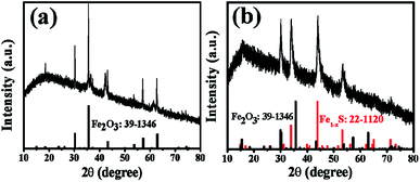
The FESEM image and XRD pattern of as-prepared MIL-88 (Fe) are presented in Fig. S1 and S2 (ESI†). As expected, MIL-88(Fe) exhibits a shuttle-like structure with a smooth surface and size of ∼3 μm in length, and its XRD pattern is consistent with the previous report.27 The XRD patterns of Fe2O3@C and Fe2O3/Fe1−xS@C (Fig. 1a and b) can be well indexed to the cubic maghemite Fe2O3 phase (JCPDS card no. 39-1346) and the hexagonal pyrrhotite Fe1−xS phase (JCPDS card no. 22-1120), respectively. In addition, a broad diffraction peak located at around 24° is attributed to the amorphous carbon coated on the surface of the nanoparticles.30,31 From the SEM images of Fe2O3@C and Fe2O3/Fe1−xS@C (as shown in Fig. 2a and c), it can be clearly seen that the products can maintain the original shuttle-like shape of the precursor, and the magnified FESEM images (Fig. 2b and d) show that the surfaces of Fe2O3@C and Fe2O3/Fe1−xS@C are composed of numerous nanoparticles. The elemental mapping measured via energy dispersive spectroscopy (EDS) confirms the co-existence of Fe, O, and C elements in Fe2O3@C, as shown in Fig. S3 (ESI†). Apart from Fe, O, and C, S element is also observed in the EDS mapping of Fe2O3/Fe1−xS@C, as shown in Fig. S4 (ESI†). In addition, the element contents of Fe2O3@C and Fe2O3/Fe1−xS@C are listed in Table S1 (ESI†). The Fe contents are almost the same in both samples. Notably, the carbon content in Fe2O3/Fe1−xS@C is slightly higher than that in Fe2O3@C, and the probable reason is that the sublimated sulfur consumes more oxide element, thus resulting in the relative higher carbon content.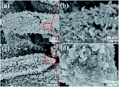 | ||
| Fig. 2 FESEM images at low and high-magnification of (a and b) Fe2O3@C and (c and d) Fe2O3/Fe1−xS@C. | ||
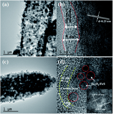
The transmission electron microscope (TEM) image of Fe2O3@C in Fig. 3a shows that Fe2O3 nanoparticles with sizes ranging from 20 to 100 nm are uniformly distributed in the amorphous carbon matrix. Besides, the magnified TEM image (Fig. 3b) displays the thickness of the amorphous carbon layer to be about 3–5 nm, which exhibits a highly ordered lattice fringe with a spacing of 2.5 Å, corresponding to the (311) plane of Fe2O3. Similarly, as shown in Fig. 3c and d, the size of Fe2O3/Fe1−xS nanoparticles is about 10–50 nm, and the thickness of the amorphous carbon layer is about 8 nm. Moreover, the magnified TEM image of Fe2O3/Fe1−xS@C in Fig. 3d shows the clear lattice fringes of Fe2O3 with a spacing of 2.5 Å and Fe1−xS with a spacing of 1.9 Å, corresponding to the (311) plane of Fe2O3 and the (220) plane of Fe1−xS.
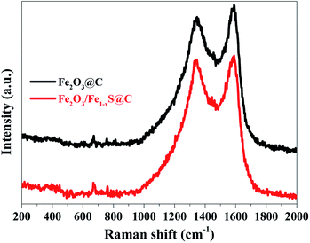
The specific surface areas and corresponding pore size distributions of Fe2O3@C and Fe2O3/Fe1−xS@C were further studied by nitrogen adsorption–desorption isotherms based on the Brunauer–Emmett–Teller (BET) method, and the results are shown in Fig. 4a and b. Fe2O3@C exhibits a typical IV isotherm along with an obvious H1 hysteresis, which shows the feature of the mesoporous structure. However, the Fe2O3/Fe1−xS@C shows a typical III isotherm, implying the co-existence of microporous and mesoporous structures in the samples.32,33 The corresponding pore size distributions are shown in the inset of Fig. 4a and b. It can be found that the pores in Fe2O3@C are mainly distributed in the range of mesopores, whereas a hierarchically porous structure with micro/mesopores exists in Fe2O3/Fe1−xS@C. Notably, the difference between Fe2O3/Fe1−xS@C and Fe2O3@C on N2 adsorption/desorption isotherms and pore size distributions should be ascribed to the sulfidation process, creating micropores in the resultant Fe2O3/Fe1−xS@C, which contributes to its high specific surface area. Particularly, the specific surface area of Fe2O3/Fe1−xS@C is 183.4 m2 g−1, which is larger than that of Fe2O3@C (133.5 m2 g−1). Apparently, the large specific surface area could supply a good contact between electrode materials and electrolyte, and the hierarchically mesoporous and microporous structure will be beneficial to accommodate the volume changes, resulting in the superior stability and fast Li+ diffusion. The existence of carbon materials in Fe2O3@C and Fe2O3/Fe1−xS@C composites are confirmed by Raman spectroscopy, as shown in Fig. 5. Two main peaks located at around 1340 cm−1 and 1580 cm−1 are assigned to D (disordered carbon or defective graphitic structure) and G (graphitic carbon) bands, respectively. The peak intensity ratio of the D band/G band (ID/IG) characterizes the degree of disorder or defects in the carbon structure in the samples.34 The values of ID/IG for Fe2O3@C and Fe2O3/Fe1−xS@C composites are calculated to be 0.94 and 0.96, respectively, indicating the co-existence of both amorphous and graphitic carbon.35,36 The other weak peaks located at about 380, 400, 680, and 750 cm−1 represent Fe–O and Fe–S Raman modes. Moreover, the absence of two characteristic peaks (214 and 280 cm−1 corresponding to A1g and Eg) of Fe2O3 in the Raman spectra of Fe2O3@C and Fe2O3/Fe1−xS@C should be attributed to the phonon confinement effect in which the Fe2O3 signal is blocked by the carbon in Fe2O3@C and Fe2O3/Fe1−xS@C composites.37–39
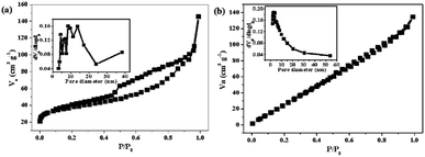 | ||
| Fig. 4 N2 adsorption/desorption isotherms of (a) Fe2O3@C and (b) Fe2O3/Fe1−xS@C. Inset is the corresponding pore size distributions. | ||
The electrochemical impedance spectra (EIS) of Fe2O3@C and Fe2O3/Fe1−xS@C electrodes were measured in the frequency range from 0.1 Hz to 100 kHz after 100 charge/discharge cycles, and the results are shown in Fig. 6a and b. The equivalent circuit model shown in the inset of Fig. 6a was used to fit and analyze the Nyquist plots. In general, the Nyquist plots are composed of an indistinct depressed semicircle in a high frequency related to the resistance from the solid electrolyte interface layer (Rf), an obvious large semicircle in the middle frequency region representing the charge-transfer resistance (Rct), and an inclined line in low frequency region corresponding to the Warburg diffusion resistance (Zw). The fitted Rct values for Fe2O3@C and Fe2O3/Fe1−xS@C electrodes are about 503 and 118 Ω, respectively, indicating the enhanced charge transfer of the Fe2O3/Fe1−xS heterostructure. The reduced Rct will increase the electron transfer kinetics and subsequently improve the rate capability of the Fe2O3/Fe1−xS@C electrode. Moreover, the Fe2O3/Fe1−xS@C electrode exhibits a more vertically inclined line than that of Fe2O3@C, showing its significant capacitive contribution behavior, which results in a fast charging–discharging rate.40,41
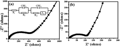 | ||
| Fig. 6 EIS plots of (a) Fe2O3@C and (b) Fe2O3/Fe1−xS@C electrodes after 100 cycles, and inset of (a) is the equivalent circuit model. | ||
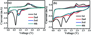
Fig. 7a and b show the initial four CV curves of Fe2O3@C and Fe2O3/Fe1−xS@C electrodes between 0.005 and 3.0 V at a scan rate of 0.2 mV s−1, respectively. The irreversible broad and sharp cathodic peak at around 0.6 V for the Fe2O3@C electrode as well as a minor peak at 1.1 V and a broad peak centered at 0.6 V for the Fe2O3/Fe1−xS@C electrode in the first cathodic scan can be ascribed to the decomposition of the electrolyte with the formation of the solid electrolyte interface film and the reduction of Fe2O3 and Fe1−xS to form metallic Fe and amorphous Li2O.42,43 The related electrochemical reactions can be described as follows:
| Fe2O3 + 6Li+ + 6e− → 3Li2O + 2Fe | (1) |
| Fe1−xS + 2Li+ + 2e− → Li2S + Fe1−x | (2) |
From the second cycle, the cathodic peaks of both electrodes particularly the Fe2O3/Fe1−xS@C electrode move to a higher potential, which is related to the structural change of metal oxides and sulfides caused by first lithiation/de-lithiation.44 A higher potential favors Li+ insertion in electrode materials, leading to better electrochemical performance.45 For the first anodic sweep, there are two peaks at 1.6 and 1.8 V for the Fe2O3@C electrode, and 1.7 and 2.3 V for Fe2O3/Fe1−xS@C, indicating the oxidation of metallic Fe to Fe2O3 and Fe1−xS via a multistep oxidation process.46,47 The corresponding electrochemical reaction can be summarized as follows:
| 2Fe + 3Li2O − 6e− → Fe2O3 + 6Li+ | (3) |
| Fe1−x + Li2S − 2e− → Fe1−xS + 2Li+ | (4) |
The CV peaks almost overlapped with each other after the second cycle, indicating their superior electrochemical stability.
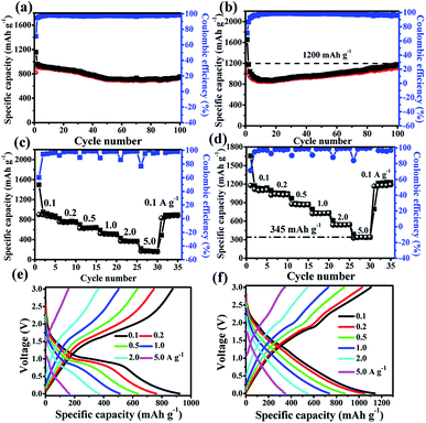
Fig. 8a and b compare the cycle stabilities of Fe2O3@C and Fe2O3/Fe1−xS@C electrodes at a current density of 0.1 A g−1 for 100 cycles. The cycling stability of the Fe2O3@C electrode is attenuated slightly in the first 40 cycles, and the capacity keeps at 786 mA h g−1 after 100 cycles, whereas the capacity of the Fe2O3/Fe1−xS@C electrode decays in the first 10 cycles, and then shows an obvious increase in the subsequent cycles, implying its excellent cycling stability. The reversible capacity of the Fe2O3/Fe1−xS@C electrode can be maintained at 1200 mA h g−1 with an approximately 99% capacity retention owing to the synergistic effects of Fe2O3 and Fe1−xS, which is much higher than that of the Fe2O3@C electrode. The Fe2O3/Fe1−xS@C electrode after 100 cycles was measured via FESEM (Fig. S5, ESI†), and no obvious change can be detected after cycling, indicating the excellent stability of the electrode materials. Furthermore, the rate performances of Fe2O3@C and Fe2O3/Fe1−xS@C electrodes were also evaluated at different current densities ranging from 0.1, 0.2, 0.5, 1.0, 2.0, and 5.0 A g−1, and the results are shown in Fig. 8c and d. The corresponding reversible specific capacities of Fe2O3@C (Fe2O3/Fe1−xS@C) are about 880.5 (1139.7), 761.1 (1047), 644.5 (875.6), 511.2 (735.3), 358.9 (546.1) and 140 (345) mAh g−1. When the current density returns to 0.1 A g−1, the reversible capacities can be recovered to 900 (1189.2) mAh g−1, showing the excellent rate capability.48 In addition, the lithium storage performance of the Fe2O3/Fe1−xS@C electrode at a current density of 10 A g−1 was also tested, and the results are shown in Fig. S6 (ESI†). Even though at such a high current density, the capacity can still be maintained at 98 mA h g−1. The main reason should be ascribed to the unique structure and the carbon matrix, which can facilitate the transport of Li+ and electrons, thus leading to excellent rate capability. Fig. 8e and f display the corresponding charge/discharge curves at each current density for Fe2O3@C and Fe2O3/Fe1−xS@C electrodes, respectively. It can be seen that the Fe2O3/Fe1−xS@C electrode shows less polarization at high current densities than Fe2O3@C. More importantly, it is obvious that the capacities of the Fe2O3/Fe1−xS@C electrode at each current density are greatly higher than those of Fe2O3@C electrode, particularly at a high current density of 5.0 A g−1. In addition, we compared the performance of the Fe2O3/Fe1−xS@C in this study with other Fe-based electrodes reported in previous literatures (Table S2, ESI†). The results show that the Fe2O3/Fe1−xS@C exhibits the highest specific capacity and excellent rate capability. The outstanding electrochemical performance of the Fe2O3/Fe1−xS@C electrode can be ascribed to (i) the excellent charge transfer ability due to the introduction of Fe1−xS and the formation of the heterostructure between Fe2O3 and Fe1−xS; (ii) the short ion-diffusion pathways due to the ultra-small nanoparticles; (iii) the excellent structural stability ensured by the carbon buffer and porous structure.
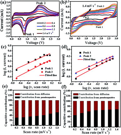
It is well known that there are two typical types of energy storage behaviors in LIBs: redox pseudocapacitive process taking placing on the surface of the electrode materials, and the diffusion-controlled process in the bulk of the electrode materials. In order to further study the fast reaction kinetics of different electrode materials, according to the Trasatti analysis reported by Dunn et al., CV tests at various sweep rates from 0.2 to 1.4 mV s−1 were carried out, which can quantify and calculate the contribution percentage from the pseudocapacitive effect and diffusion-controlled Li+ insertion process.24,49 As shown in Fig. 9a and b, all peak current intensity (i) increase with the increase in the scan rate (ν), and their relationship follow the equation: i = aνb,50 where a and b both are adjustable values. When the value of b is 0.5, the ionic diffusion is dominant, whereas when b = 1, the reaction is mostly pseudocapacitive behavior controlled. According to previous literature,23,51 the b value can be calculated from the slope of the fitted line based on log(i) versus log(ν) plots, and the fitted results are shown in Fig. 9c and d for Fe2O3@C and Fe2O3/Fe1−xS@C electrodes, respectively. The b values for the selected peak 1 and peak 2 of the Fe2O3@C electrode are 0.69 and 0.78, respectively, which are lower than those of the Fe2O3/Fe1−xS@C electrode (peak 1, 0.79; peak 2, 0.85), indicating the higher pseudocapacitive contribution of the Fe2O3/Fe1−xS@C electrode than that of Fe2O3@C. In addition, the total current intensity can be divided into two parts according to the following eqn (5):52,53
| i = k1v + k2v1/2 | (5) |
4. Conclusions
In conclusion, an effective approach, to design the Fe2O3/Fe1−xS heterostructure coated by an amorphous carbon layer via annealing MOFs and sublimed sulfur, was developed. When evaluated as the anode material for LIBs, Fe2O3/Fe1−xS@C features more excellent Li+ storage performance (1200 mA h g−1 at 0.1 A g−1 after 100 cycles) and outstanding rate capability (345 mA h g−1 at 5.0 A g−1) as compared with Fe2O3@C. The improvement in the Li+ diffusion capability and charge-transfer ability is mainly responsible for the extraordinary performance of the Fe2O3/Fe1−xS@C electrode. The sulfidation strategy developed in this study should be a promising way to prepare other carbon-coated metal oxide/sulfide heterostructures from MOFs with high capacity and superior rate for LIBs.Conflicts of interest
There are no conflicts to declare.Acknowledgements
This work is supported by the Provincial Natural Science Foundation of Anhui (1908085ME120), Primary Research and Development Program of Anhui Province (201904a05020087), Doctoral Fund of Ministry of Education of China (No. 2018M642356), Innovative Research Team of Anhui Provincial Education Department (2016SCXPTTD), Natural Science Project of the Jiangsu Higher Education Institutions (19KJB480001, 18KJA430006), National & Local Joint Engineering Research Center for Deep Utilization Technology of Rock-salt Resource (SF201802, SF201803), Key Discipline of Material Science and Engineering of Suzhou University (2017XJZDXK3).Notes and references
- B. Kang and G. Ceder, Battery materials for ultrafast charging and discharging, Nature, 2009, 458, 190–193 CrossRef CAS PubMed
.
- X. Zhang, G. Zhu, M. Wang, J. Li, T. Lu and L. Pan, Covalent-organic-frameworks derived N-doped porous carbon materials as anode for superior long-life cycling lithium and sodium ion batteries, Carbon, 2017, 116, 686–694 CrossRef CAS
.
- C. Yingying, G. Kaiming, G. Hongbo, A. Huixiang, P. Jie, L. Yayuan, C. Xueqin, Z. Junwei and G. Hongwei, Metal-Oleate Complex Derived Bimetallic Oxides Nanoparticles Encapsulated in 3D Graphene Networks as Anodes for Efficient Lithium Storage with Pseudocapacitance, Nano-Micro Lett., 2019, 11, 15 CrossRef
.
- S. Yu, V. M. Hong Ng, F. Wang, Z. Xiao, C. Li, L. B. Kong, W. Que and K. Zhou, Synthesis and application of iron-based nanomaterials as anodes of lithium-ion batteries and supercapacitors, J. Mater. Chem. A, 2018, 6, 9332–9367 RSC
.
- L. Kong, M. Zhong, W. Shuang, Y. Xu and X.-H. Bu, Electrochemically active sites inside crystalline porous materials for energy storage and conversion, Chem. Soc. Rev., 2020, 49, 2378–2407 RSC
.
- S. Zheng, X. Li, B. Yan, Q. Hu, Y. Xu, X. Xiao, H. Xue and H. Pang, Transition-metal (Fe, Co, Ni) based metal-organic frameworks for electrochemical energy storage, Adv. Energy Mater., 2017, 7, 1602733 CrossRef
.
- D. Pan, N. Wan, Y. Ren, W. Zhang, X. Lu, Y. Wang, Y. S. Hu and Y. Bai, Enhanced structural and electrochemical stability of self-similar rice-shaped SnO2 nanoparticles, ACS Appl. Mater. Interfaces, 2017, 9, 9747–9755 CrossRef CAS PubMed
.
- D. Wang, T. Xu, Y. Li, D. Pan, X. Lu, Y. S. Hu, S. Dai and Y. Bai, Integrated surface functionalization of Li-rich cathode materials for Li-ion batteries, ACS Appl. Mater. Interfaces, 2018, 10, 41802–41813 CrossRef CAS PubMed
.
- M. Zhang, E. Liu, T. Cao, H. Wang, C. Shi, J. Li, C. He, F. He, L. Ma and N. Zhao, Sandwiched graphene inserted with graphene-encapsulated yolk–shell γ-Fe2O3 nanoparticles for efficient lithium ion storage, J. Mater. Chem. A, 2017, 5, 7035–7042 RSC
.
- X. Zhang, M. Wang, G. Zhu, D. Li, D. Yan, T. Lu and L. Pan, Porous cake-like TiO2 derived from metal-organic frameworks as superior anode material for sodium ion batteries, Ceram. Int., 2017, 43, 2398–2402 CrossRef CAS
.
- Y. Yang, W. Yuan, X. Zhang, C. Wang, Y. Yuan, Y. Huang, Y. Ye, Z. Qiu and Y. Tang, A review on FexOy-based materials for advanced lithium-ion batteries, Renewable Sustainable Energy Rev., 2020, 127, 109884 CrossRef CAS
.
- T. Jiang, F. Bu, X. Feng, I. Shakir, G. Hao and Y. Xu, Porous Fe2O3 nanoframeworks encapsulated within three-dimensional graphene as high-performance flexible anode for lithium-ion battery, ACS Nano, 2017, 11, 5140–5147 CrossRef CAS PubMed
.
- B. Sun, S. Lou, Z. Qian, P. Zuo, C. Du, Y. Ma, H. Huo, J. Xie, J. Wang and G. Yin, Pseudocapacitive Li+ storage boosts ultrahigh rate performance of structure-tailored CoFe2O4@Fe2O3 hollow spheres triggered by engineered surface and near-surface reactions, Nano Energy, 2019, 66, 104179 CrossRef CAS
.
- X. Lv, J. Deng, B. Wang, J. Zhong, T. K. Sham and X. Sun, γ-Fe2O3@CNTs anode materials for lithium ion batteries investigated by electron energy loss spectroscopy, Chem. Mater., 2017, 29, 3499–3506 CrossRef CAS
.
- K. Lee, S. Shin, T. Degen, W. Lee and Y. S. Yoon, In situ analysis of SnO2/Fe2O3/RGO to unravel the structural collapse mechanism and enhanced electrical conductivity for lithium-ion batteries, Nano Energy, 2017, 32, 397–407 CrossRef CAS
.
- N. F. W. Thissen, M. A. Verheijen, R. G. Houben, C. van der Marel, W. M. M. Kessels and A. A. Bol, Synthesis of single-walled carbon nanotubes from atomic-layer-deposited Co3O4 and Co3O4/Fe2O3 catalyst films, Carbon, 2017, 121, 389–398 CrossRef CAS
.
- F. Zheng, M. He, Y. Yang and Q. Chen, Nano electrochemical reactors of Fe2O3 nanoparticles embedded in shells of nitrogen-doped hollow carbon spheres as high-performance anodes for lithium-ion batteries, Nanoscale, 2015, 7, 3410–3417 RSC
.
- S. L. Zhang, B. Y. Guan, H. B. Wu and X. W. Lou, Metal-organic framework-assisted synthesis of compact Fe2O3 nanotubes in Co3O4 host with enhanced lithium storage properties, Nano-Micro Lett., 2018, 10, 44 CrossRef PubMed
.
- X. Zhang, X. Gao, Z. Wu, M. Zhu, Q. Jiang, S. Zhou, K. Hong and Z. Rao, Effects of binders on electrochemical sodium storage performance with porous CoFe2O4 nanocubes derived from metal-organic frameworks, Chem. Phys., 2019, 523, 124–129 CrossRef CAS
.
- X. Zhang, W. Qin, D. Li, D. Yan, B. Hu, Z. Sun and L. Pan, Metal–organic framework derived porous CuO/Cu2O composite hollow octahedrons as high performance anode materials for sodium ion batteries, Chem. Commun., 2015, 51, 16413–16416 RSC
.
- Z. Xiu, M. H. Alfaruqi, J. Gim, J. Song, S. Kim, T. V. Thi, P. T. Duong, J. P. Baboo, V. Mathew and J. Kim, Hierarchical porous anatase TiO2 derived from a titanium metal–organic framework as a superior anode material for lithium ion batteries, Chem. Commun., 2015, 51, 12274–12277 RSC
.
- E. F. Rodriguez, F. Xia, D. Chen, A. F. Hollenkamp and R. A. Caruso, N-doped Li4Ti5O12 nanoflakes derived from 2D protonated titanate for high performing anodes in lithium ion batteries, J. Mater. Chem. A, 2016, 4, 7772–7780 RSC
.
- V. Augustyn, P. Simon and B. Dunn, Pseudocapacitive oxide materials for high-rate electrochemical energy storage, Energy Environ. Sci., 2014, 7, 1597–1614 RSC
.
- V. Augustyn, J. Come, M. A. Lowe, J. W. Kim, P.-L. Taberna, S. H. Tolbert, H. D. Abruña, P. Simon and B. Dunn, High-rate electrochemical energy storage through Li+ intercalation pseudocapacitance, Nat. Mater., 2013, 12, 518 CrossRef CAS PubMed
.
- P. Simon, Y. Gogotsi and B. Dunn, Where do batteries end and supercapacitors begin?, Science, 2014, 343, 1210–1211 CrossRef CAS PubMed
.
- Z. Tong, H. Xu, G. Liu, J. Zhao and Y. Li, Pseudocapacitive effect and Li+ diffusion coefficient in three-dimensionally ordered macroporous vanadium oxide for energy storage, Electrochem. Commun., 2016, 69, 46–49 CrossRef CAS
.
- X. Xu, J. Li, M. Wang, Y. Liu, T. Lu and L. Pan, Shuttle-like porous carbon rods from carbonized metal–organic frameworks for high-performance capacitive deionization, ChemElectroChem, 2016, 3, 993–998 CrossRef CAS
.
- X. Zhang, W. Ou-Yang, G. Zhu, T. Lu and L. Pan, Shuttle-like carbon-coated FeP derived from metal-organic frameworks for lithium-ion batteries with superior rate capability and long-life cycling performance, Carbon, 2019, 143, 116–124 CrossRef CAS
.
- L. Wang, Y. Zhang, X. Li, Y. Xie, J. He, J. Yu and Y. Song, The MIL-88A-derived Fe3O4-carbon hierarchical nanocomposites for electrochemical sensing, Sci. Rep., 2015, 5, 14341 CrossRef CAS PubMed
.
- S. Surblé, C. Serre, C. Mellot-Draznieks, F. Millange and G. Férey, A new isoreticular class of metal-organic-frameworks with the MIL-88 topology, Chem. Commun., 2006, 284–286 RSC
.
- Y. Jia, Y. Wang, L. Dong, J. Huang, Y. Zhang, J. Su and J. Zang, A hybrid of titanium nitride and nitrogen-doped amorphous carbon supported on SiC as a noble metal-free electrocatalyst for oxygen reduction reaction, Chem. Commun., 2015, 51, 2625–2628 RSC
.
- X. Liu, T. Chen, H. Chu, L. Niu, Z. Sun, L. Pan and C. Q. Sun, Fe2O3-reduced graphene oxide composites synthesized via microwave-assisted method for sodium ion batteries, Electrochim. Acta, 2015, 166, 12–16 CrossRef CAS
.
- X. Zhang, G. Zhu, D. Yan, T. Lu and L. Pan, MnO@C nanorods derived from metal-organic frameworks as anode for superiorly stable and long-life sodium-ion batteries, J. Alloys Compd., 2017, 710, 575–580 CrossRef CAS
.
- J. Li, J. Li, D. Yan, S. Hou, X. Xu, T. Lu, Y. Yao, W. Mai and L. Pan, Design of pomegranate-like clusters with NiS2 nanoparticles anchored on nitrogen-doped porous carbon for improved sodium ion storage performance, J. Mater. Chem. A, 2018, 6, 6595–6605 RSC
.
- N. Zheng, G. Jiang, X. Chen, J. Mao, N. Jiang and Y. Li, Battery separators functionalized with edge-rich MoS2/C hollow microspheres for the uniform deposition of li2s in high-performance lithium–sulfur batteries, Nano-Micro Lett., 2019, 11, 43 CrossRef
.
- M. Gockeln, S. Pokhrel, F. Meierhofer, J. Glenneberg, M. Schowalter, A. Rosenauer, U. Fritsching, M. Busse, L. Mädler and R. Kun, Fabrication and performance of Li4Ti5O12/C Li-ion battery electrodes using combined double flame spray pyrolysis and pressure-based lamination technique, J. Power Sources, 2018, 374, 97–106 CrossRef CAS
.
- Y. Huang, M. Zheng, Z. Lin, B. Zhao, S. Zhang, J. Yang, C. Zhu, H. Zhang, D. Sun and Y. Shi, Flexible cathodes and multifunctional interlayers based on carbonized bacterial cellulose for high-performance lithium–sulfur batteries, J. Mater. Chem. A, 2015, 3, 10910–10918 RSC
.
- Y. Fang, L. Xiao, X. Ai, Y. Cao and H. Yang, Hierarchical carbon framework wrapped Na3V2(PO4)3 as a superior high-rate and extended lifespan cathode for sodium-ion batteries, Adv. Mater., 2015, 27, 5895–5900 CrossRef CAS PubMed
.
- J. Qian, M. Zhou, Y. Cao, X. Ai and H. Yang, Template-free hydrothermal synthesis of nanoembossed mesoporous LiFePO4 microspheres for high-performance lithium-ion batteries, J. Phys. Chem. C, 2010, 114, 3477–3482 CrossRef CAS
.
- Y. Wang, C. Wang, Y. Wang, H. Liu and Z. Huang, Superior sodium-ion storage performance of Co3O4@nitrogen-doped carbon: derived from a metal-organic framework, J. Mater. Chem. A, 2016, 4, 5428–5435 RSC
.
- J. Wang, J. Polleux, J. Lim and B. Dunn, Pseudocapacitive contributions to electrochemical energy storage in TiO2 (anatase) nanoparticles, J. Phys. Chem. C, 2007, 111, 14925–14931 CrossRef CAS
.
- J. Qu, Y. X. Yin, Y. Q. Wang, Y. Yan, Y. G. Guo and W. G. Song, Layer structured α-Fe2O3 nanodisk/reduced graphene oxide composites as high-performance anode materials for lithium-ion batteries, ACS Appl. Mater. Interfaces, 2013, 5, 3932–3936 CrossRef CAS PubMed
.
- C. Zhao, X. Shao, Y. Zhang and X. Qian, Fe2O3/reduced graphene oxide/Fe3O4 composite in situ grown on Fe foil for high-performance supercapacitors, ACS Appl. Mater. Interfaces, 2016, 8, 30133–30142 CrossRef CAS PubMed
.
- J. Shao, J. Zhang, J. Jiang, G. Zhou and M. Qu, α-Fe2O3@CNSs nanocomposites as superior anode materials for lithium-ion batteries, Electrochim. Acta, 2011, 56, 7005–7011 CrossRef CAS
.
- M. Gao, P. Zhou, P. Wang, J. Wang, C. Liang, J. Zhang and Y. Liu, Fe2O3/C anode materials of high capacity and cycle stability for lithium-ion batteries synthesized by carbothermal reduction, J. Alloys Compd., 2013, 565, 97–103 CrossRef CAS
.
- B. Wu, H. Song, J. Zhou and X. Chen, Iron sulfide-embedded carbon microsphere anode material with high-rate performance for lithium-ion batteries, Chem. Commun., 2011, 47, 8653–8655 RSC
.
- Y. Xu, W. Li, F. Zhang, X. Zhang, W. Zhang, C. S. Lee and Y. Tang, In situ incorporation of FeS nanoparticles/carbon nanosheets composite with an interconnected porous structure as a high-performance anode for lithium ion batteries, J. Mater. Chem. A, 2016, 4, 3697–3703 RSC
.
- Z. Li, Z. Xu, X. Tan, H. Wang, C. M. B. Holt, T. Stephenson, B. C. Olsen and D. Mitlin, Mesoporous nitrogen-rich carbons derived from protein for ultra-high capacity battery anodes and supercapacitors, Energy Environ. Sci., 2013, 6, 871–878 RSC
.
- T. Brezesinski, J. Wang, S. H. Tolbert and B. Dunn, Ordered mesoporous α-MoO3 with iso-oriented nanocrystalline walls for thin-film pseudocapacitors, Nat. Mater., 2010, 9, 146 CrossRef CAS PubMed
.
- J. B. Cook, H. S. Kim, Y. Yan, J. S. Ko, S. Robbennolt, B. Dunn and S. H. Tolbert, Mesoporous MoS2 as a transition metal dichalcogenide exhibiting pseudocapacitive Li and Na-ion charge storage, Adv. Energy Mater., 2016, 6, 1501937 CrossRef
.
- H. Liu, Z. Bi, X. G. Sun, R. R. Unocic, M. P. Paranthaman, S. Dai and G. M. Brown, Mesoporous TiO2–B microspheres with superior rate performance for lithium ion batteries, Adv. Mater., 2011, 23, 3450–3454 CrossRef CAS PubMed
.
- H. Kim, M. G. Kim and J. Cho, Unique structural changes of three-dimensionally ordered macroporous TiO2 electrode materials during electrochemical cycling, Adv. Energy Mater., 2012, 2, 1425–1432 CrossRef CAS
.
- H. X. Dang, Y. M. Lin, K. C. Klavetter, T. H. Cell, A. Heller and C. B. Mullins, Lithium insertion/deinsertion characteristics of nanostructured amorphous tantalum oxide thin films, ChemElectroChem, 2014, 1, 158–164 CrossRef
.
- L. Zhang, K. Zhao, Y. Luo, Y. Dong, W. Xu, M. Yan, W. Ren, L. Zhou, L. Qu and L. Mai, Acetylene black induced heterogeneous growth of macroporous CoV2O6 nanosheet for high-rate pseudocapacitive lithium-ion battery anode, ACS Appl. Mater. Interfaces, 2016, 8, 7139–7146 CrossRef CAS PubMed
.
Footnote |
| † Electronic supplementary information (ESI) available. See DOI: 10.1039/d0na00372g |
| This journal is © The Royal Society of Chemistry 2020 |

