
 Open Access Article
 This Open Access Article is licensed under a Creative Commons Attribution-Non Commercial 3.0 Unported Licence
Bimetallic and postsynthetically alloyed PtCu nanostructures with tunable reactivity for the methanol oxidation reaction†
Haiyan
Xiang‡
a,
Yueshao
Zheng‡
b,
Yue
Sun
a,
Tingting
Guo
c,
Pei
Zhang
a,
Wei
Li
a,
Shiwei
Kong
a,
Miray
Ouzounian
d,
Hong
Chen
e,
Huimin
Li
a,
Travis Shihao
Hu
*d,
Gang
Yu
*a,
Yexin
Feng
*b and
Song
Liu
 *a
*a
aInstitute of Chemical Biology and Nanomedicine (ICBN), State Key Laboratory of Chemo/Biosensing and Chemometrics, College of Chemistry and Chemical Engineering, Hunan University, Changsha 410082, P. R. China. E-mail: yuganghnu@163.com; liusong@hnu.edu.cn
bHunan Provincial Key Laboratory of Low-Dimensional Structural Physics and Devices, School of Physics and Electronics, Hunan University, Changsha 410082, P. R. China. E-mail: yexinfeng@hnu.edu.cn
cKey Laboratory of Yunnan Provincial Higher Education Institutions for Organic Optoelectronic Materials and Devices, Kunming University, Kunming 650000, P. R. China
dDepartment of Mechanical Engineering, California State University, Los Angeles, CA 90032, USA. E-mail: shu17@calstatela.edu
eSchool of Materials Science and Energy Engineering, Foshan University, Foshan 528000, P. R. China
First published on 4th March 2020
Abstract
Designing effective catalysts by controlling morphology and structure is key to improving the energy efficiency of fuel cells. A good understanding of the effects of specific structures on electrocatalytic activity, selectivity, and stability is needed. Here, we propose a facile method to synthesize PtCu bimetallic nanostructures with controllable compositions by using Cu nanowires as a template and ascorbic acid as a reductant. A further annealing process provided the alloy PtCu with tunable crystal structures. The combination of distinct structures with tunable compositions in the form of PtCu nanowires provides plenty of information for better understanding the reaction mechanism during catalysis. HClO4 cyclic voltammetry (CV) tests confirmed that various phase transformations occurred in bimetallic and alloy samples, affecting morphology and unit cell structures. Under a bifunctional synergistic effect and the influence of the insertion of a second metal, the two series of structures show superior performance toward methanol electrooxidation. Typically, the post-product alloy A-Pt14Cu86 with a cubic structure (a = 3.702 Å) has better methanol oxidation reaction (MOR) catalysis performance. Density functional theory (DFT) calculations were performed to determine an optimal pathway using the Gibbs free energy and to verify the dependence of the electrocatalytic performance on the lattice structure via overpotential changes. Bimetallic PtCu has high CO tolerance, maintaining high stability. This work provides an approach for the systematic design of novel catalysts and the exploration of electrocatalytic mechanisms for fuel cells and other related applications.
1. Introduction
High efficiency and low emission renewable fuel cells are considered to be a next-generation energy technology and continuously draw a great deal of attention.1 To achieve a transition to ‘clean’ energy, many researchers have focused on designing anode and cathode catalysts,2,3 related to the oxygen evolution reaction in direct methanol fuel cells (DMFCs)4 and the oxygen reduction reaction in proton exchange membrane fuel cells (PEMFCs).5–7 In particular, methyl alcohol is a clean, low-cost and high energy density energy source, which has a promising future for fuel cell applications.8,9 The electronic exchange of O anions from methanol is still mainly enhanced by the noble metal Pt. In order to expand the number of available pure Pt active sites,8 many efforts have been made to tune the morphologies of Pt-based catalysts by developing various Pt nanostructures,10,11 for example, nanosheets,12,13 nanodendrites,14 smaller sized nanoparticles,15 and so on.16,17 To reduce the usage of costly Pt and simultaneously increase catalytic efficiency, other less expensive 3d-transition metals, e.g., Fe, Co, Ni, and Cu, have been combined with Pt to form multimetallic structures.18–20 These catalysts show several benefits that enhance their performances.21 Firstly, doping other atoms into Pt can result in lattice strain effects. Secondly, the insertion of additional metallic atoms with distinctive chemical properties could lead to electrical variations between surrounding Pt atoms, which are referred to as surface ligand effects. Thirdly, on a hybridized surface, geometric effects can generally cause different atomic arrangements. Fourthly, synergetic effects can help to form multiple adsorption spots on the catalyst surface to facilitate reactions.22 Introducing the transition metals Fe, Co and Ni can also lead to a decrease in the binding energy of adsorbed oxygen, which can show promise for the oxygen reduction reaction (ORR).20,23 Recently the introduction of the low-cost base metal Cu has attracted much attention for developing direct methanol fuel cells, as Cu can induce lattice strain effects24–26 and absorb oxygenated species (OHads) at negative potentials to further facilitate Pt–COads analogue oxidation.27,28PtCu catalysts with different morphologies and configurations (e.g., bimetals and alloys) have been extensively explored to study their effects on the oxygen evolution reaction in methanol solution.29–31 For example, Xia and co-workers used a galvanic replacement method to prepare M–Cu porous bimetallic nanostructures. The resultant structures from the sacrificial template method have significant numbers of cavities and active open areas, enhancing the electrocatalytic performance.32 In comparison, depositing a Pt catalyst on a one-dimensional Cu nanowire support usually renders the catalyst with higher durability compared to traditional carbon supports, which always suffer from Ostwald ripening, degradation and aggregation during the catalytic process.21,33 PtCu alloy nanostructures with diverse morphologies, for instance, nanocages,24 nanowires,2,34 nanoframes30 and nanodendrites,35 have been synthesized and developed for methanol oxidation reaction (MOR) applications.36,37 Optimized Cu insertion into the alloy structure can modify the electronic environment and facilitate the generation of more intermediate oxides, with highly improved MOR electrocatalytic performance.38 These reported PtCu catalysts with distinct structures present high MOR performance; however, only one specific structure with a composition involving a bimetal or alloy was concentrated on and discussed. A simultaneous and systematic investigation into the effects of these two distinct structures in one frame on the corresponding electrocatalytic behavior is highly desirable.
Herein, we prepared Pt nanoparticles deposited on basal metallic Cu nanowires with tunable compositions, in which earth-abundant Cu in a bimetallic structure served as the skeleton/support for the Pt nanoparticles in order to increase the active surface area. Furthermore, PtCu alloys with special lattice structures that relied on particular compositions were fabricated after an annealing process at 800 °C, which showed synergetic effects and functionalities in MOR catalysis. Both the bimetallic and alloy structures with tunable compositions show enhanced MOR performance. Typically, after systematic statistical analysis and a comparison of the electrochemical surface areas (ECSAs), MOR properties and CO toxicity, the bimetallic and alloy structures separately show unique advantages in terms of specific activity and catalysis durability during the MOR. We have identified the correlation between the compositions and crystal structures of the two as-prepared PtCu nanostructures after theoretical calculations. The results could have a significant impact on catalyst design, the analysis of fuel cell mechanisms, and other related applications, and could also promote MOR catalytic performance by enabling benefits from the insertion of a second metal.
2. Experimental
Materials
Copper(II) chloride dihydrate (CuCl2·2H2O), chloroplatinic acid hexahydrate (H2PtCl6·6H2O), methanol (CH3OH), perchloric acid (HClO4), D-glucose (C6H12O6), polypropylene pyrrolidone (PVP·K30), and ascorbic acid (AA, C6H8O6) were purchased from China Sinopharm Co. Ltd. 1-Hexadecylamine (HDA, C16H33NH2) and octadecylamine (ODA, C18H37NH2) were purchased from Aladdin Chemical Regent Company (Shanghai, China). Nafion was purchased from Du Pont Co. Ltd. All reagents were directly used as reactants without any purification.Synthesis of Cu nanowires
The procedure for synthesizing Cu nanowires followed our previous work,39 where 48 mg of CuCl2·2H2O, 78 mg of glucose, 97 mg of HDA (0.4 mmol), 216 mg of ODA (0.8 mmol), and 18 mL of distilled water were added to a 25 mL Teflon-lined stainless-steel autoclave. The mixture was vigorously stirred overnight, then placed into an oven at 120 °C for 4 h. Afterwards, samples were collected via centrifugation (6000 rpm) and washed using 60 °C deionized water.Synthesis of bimetallic PtCu nanowires
In a typical process, 144 mg of the above-mentioned synthesized Cu nanowires was added into a 100 mL glass bottle, and then 12 mL of ascorbic acid (AA, 0.2 mol L−1), 1 g of PVP and 10 mL of H2PtCl6 (24.4 mmol L−1) were subsequently added into the bottle, and the mixture was stirred for 30 min. N2 purging was performed for 30 min in advance to protect the reaction system. The capped glass bottle was heated in a 90 °C oil bath and vigorously stirred for 1 h, and the reddish precursor solution gradually turned black during the reaction process. The final products were washed five times using large amounts of ethanol and deionized water. The resultant solution was dried under vacuum and collected. In order to acquire PtCu nanowires with different compositions, different ratios of ascorbic acid, H2PtCl6, and PVP were mixed together (Table S1†).Synthesis of A-PtCu
The PtCu nanowires obtained above were placed into a tube furnace under a 100 sccm flow of 10% H2 and 90% Ar and kept at 800 °C for 1 h for annealing; A-PtCu was then obtained.Morphological and structural characterization
Scanning electron microscopy (SEM, Hitachi-S4800) and energy dispersive X-ray spectroscopy (EDS, Horiba 7021-H) were used to characterize the morphologies and compositions of the products. A JEOL 2100 transmission electron microscope (TEM) was used to determine the morphologies, and selected area electron diffraction (SAED) analysis was also conducted. An FEI Tecnai G2 F20 microscope operating at 200 kV was used, which allowed high-angle annular dark-field scanning TEM (HAADF-STEM) imaging and EDX spectroscopy. Shimadzu XRD-6100 apparatus (Cu-Kα radiation, λ = 0.154059 nm, 40 kV, 30 mA) was used to measure the crystal structures. X-ray photoelectron spectroscopy (XPS, Escalab 250Xi) was used to analyze the valence states and surface compositions.Electrochemical characterization
Electrochemical performance was tested using CHI 660E apparatus (Chenhua Instruments Crop, Shanghai, China) in a three-electrode system, i.e., with a glass carbon electrode (5 mm) as the working electrode, Pt foil as the counter electrode, and a saturated calomel electrode (SCE) as the reference electrode. For fabricating the working electrode, 20 μL of catalyst ink (0.1 mg mL−1) was pipetted onto the glass carbon electrode and dried in open air. Cyclic voltammetry tests were performed in 0.1 M HClO4 solution and 0.1 M HClO4 + 0.5 M CH3OH solution at a scan rate of 50 mV s−1. The electrochemically active surface area (ECSA) was measured via integrating the charge of the H2 adsorption area and calibrating this with the standard value 210 μC cmPt−2. CO stripping experiments were performed via the following procedure. Firstly, 0.1 M HClO4 solution was purged with N2 for 30 min, and then absorbed CO was collected at the electrode by applying i–t sweeps at a constant value of −0.14 V. Finally, N2 purging was carried out for 20 min to remove dissolved CO from the electrolyte, and CV was used to analyze the CO stripping process. All the potentials used in this work are referenced to SCE values.Calculation methods
All theoretical simulations relating to methanol electro-oxidation were carried out with the density functional theory (DFT) method, implemented using the Vienna ab initio simulation package (VASP).40,41 The exchange correlation energy was described via the generalized gradient approximation (GGA) in Perdew–Burke–Ernzerhof (PBE) form.42 A kinetic energy cutoff of 600 eV and the Γ-centered Monkhorst–Pack method with a k-point density of about 2π × 0.03 Å−1 were used. The atomic positions and lattice constants of all structures were relaxed until the forces acting on the atoms were less than 0.02 eV Å−1. Pt, R-PtCu, F-PtCu, and PtCu3 were modeled using periodic {110} lattices of four optimized structures with a 2 × 4 × 1 supercell that contained four metal layers. A vacuum area of 15 Å was created in the slab model to ensure negligible interactions between layers. Considering the interaction of the surface with the adsorbate, the upper two layers and the adsorbed substance were fully relaxed for all structures, while the bottom two layers were fixed. The reaction processes of the MOR were investigated under standard conditions with three possible paths; each path contains 6 electron transfer steps, as shown in Table S7.† The reaction free energy of each elementary step of methanol electrooxidation was predicted under standard conditions based on computational hydrogen electrode (CHE) theory.43 For each reaction step, the Gibbs free energy was calculated according to the formula| ΔG = ΔE + ΔZPE − TΔS | (1) |
 , according to the CHE method.43 In order to make comparisons and find the rates of steps, reaction environment factors, such as the electrode potential and solution pH, were not considered in our calculations. The fully relaxed Pt, R-PtCu, F-PtCu and PtCu3 {110} surfaces and the intermediates during methanol electrooxidation are shown in Fig. S20.† The reaction free energy values from each step are shown in Tables S8 and S9.†
3. Results and discussion
Small Pt nanoparticles deposited on Cu nanowires (NWs) with different compositions were obtained using ascorbic acid as a reductant and Cu NWs as the template substrate (Fig. 1a). The TEM image in Fig. 1c clearly shows nanoparticles on the Cu surface, and corresponding element mapping (Fig. 1e and f) demonstrates the uniform distribution of Pt on Cu. Different volumes, i.e., 2, 5, 10, 20, 25, and 30 mL, of H2PtCl6·6H2O (24.4 mmol L−1) were added to make structures with tunable compositions. From EDX testing (Fig. 2d), the corresponding Pt compositions of the final PtCu nanowire products are found to be 14, 59, 67, 78, 81, and 90%. More Pt nanoparticles are deposited on the Cu nanowires with an increased amount of precursor (Fig. S4†). Control samples without ascorbic acid were also obtained. In this case, only small numbers of elongated Pt particulates were observed on the Cu NWs (Fig. S1†). The control Pt11Cu89 nanowires showed poor electrocatalytic performance (Fig. S3†). Without ascorbic acid as a reductant, only weak galvanic displacement, where negative CuII/Cu (0.34 V) reduced PtII/Pt (1.18 V), took place to form low numbers of Pt particles on the Cu NWs. Hence, ascorbic acid plays a key role in the synthesis of Pt-decorated Cu nanowires with controllable compositions. | ||
| Fig. 1 (a) A schematic diagram of the PtCu nanowire formation process with ascorbic acid. (b) SEM, (c) TEM, (d) HAADF-STEM and (e and f) corresponding element mapping (Cu and Pt) images of Pt59Cu41 nanowires with ascorbic acid. | ||
 | ||
| Fig. 2 (a) HRTEM image and (b) SAED pattern of Pt59Cu41, (c) XRD pattern and (d) EDS spectra of different compositional PtCu nanowires with ascorbic acid. | ||
To further study the PtCu nanostructures made with ascorbic acid, HRTEM and SAED analyses were carried out to test the Pt59Cu41 sample. Fig. 2a clearly shows that the nanoparticles have a crystal lattice spacing of 0.226 nm, which corresponds to the face centered cubic (fcc) Pt(111) lattice fringe, and each distinctive growth direction of surface Pt can also be detected using the lattice fringes. The SAED image (Fig. 2b) clearly shows concentric rings, which are individually indexed to the (111), (200) and (220) planes of the fcc Pt nanostructure, suggesting again that the Pt nanostructures have different crystal growth orientations. XRD analysis results from different PtCu nanowires are shown in Fig. 2c. The XRD spectrum of Pt14Cu86 contains three major peaks at 2θ values of 43.5°, 50.7°, and 74.4°, corresponding to the (111), (200), and (220) planes of the fcc copper structure (JCPDS no. 99-0034), respectively, and two minor diffraction peaks at 2θ values of 39.7° and 46.2°, corresponding to fcc Pt (JCPDS no. 04-0802); this shows the presence of two monometallic structures and the Cu nanowire substrate.33 As the amount of H2PtCl6·6H2O is increased, the Pt(111) diffraction intensity gradually strengthens, while the intensity of Cu(111) diffraction weakens. Table S2† summarizes data relating to high intensity 2θPt(111) peak, dPt(111), full width at half-maximum (FWHM), lattice parameter (LP) (eqn (2)),45 and crystallite size (Dcryst) (eqn (3)) values, and the average diameters of Pt nanoparticles obtained from the TEM images in Fig. S4 (data in Fig. S5†). The 2θPt(111) positions and LPs of PtCu nanowires with different compositions (Table S2†) are nearly the same: 40° and 0.38 nm, respectively. The calculated crystallite sizes, which can be confirmed for the different growth directions of Pt nanoparticles on the Cu nanowires, are close to the standard Pt values. The calculated Dcryst values for the Pt nanoparticles, obtained from the broad diffraction peak FWHM values, are around 3.48 ± 1.5 nm, showing only a small change compared to the average size measured from TEM images (i.e., around 2.7 ± 0.4 nm).46
 | (2) |
 | (3) |
Thermal annealing at high temperature is the most common way to obtain an alloy structure from a bimetallic precursor.21,45 PtCu nanowires with different compositions were annealed at 800 °C to get the postsynthetic products (Fig. S6†). The morphological changes at different annealing temperatures were analyzed (Fig. S7†). The nanoparticles formed on the nanowires were initially uniform in shape and then transformed into irregular nanoparticles. Interestingly, from XRD analysis, the unit cell structure changes as the Pt content in A-PtCu is varied. As seen in Fig. 3a, the typical diffraction peaks for high Cu content A-Pt14Cu86 appeared at 2θ values of 42.2°, 49.2°, and 72.1°, corresponding to the (111), (200), and (220) planes of disordered PtCu3 (JCPDS no. 35-1358), respectively, indicating the formation of the Fm![[3 with combining macron]](https://www.rsc.org/images/entities/char_0033_0304.gif) m (225) unit cell with cubic structure (a = 3.702 Å) (Fig. S9†). Extra small diffraction peaks at 2θ values of 34.3°, 55.7°, and 61.5° imply the presence of an ordered L1 Cu3Pt phase (Pmm).45 With slight increases in the Pt content in the cases of A-Pt59Cu41 (Fig. S10a†), A-Pt67Cu33 (Fig. 3b), and A-Pt78Cu22 (Fig. S10b†), the characteristic diffraction peaks are in agreement with the standard PtCu pattern (JCPDS no. 42-1326). The typical diffraction peaks are at 39.2°, 41.0°, 47.9°, 52.6°, 62.3°, 69.5°, 71.1°, and 73.3°, corresponding to the (205), (006), (404), (241), (416), (048), (309), and (229) planes, indicating the presence of the Rm (166) unit cell (a = b = 10.703 Å, c = 13.197 Å, α = β = 90°, γ = 120°, R-centered hexagonal crystal system). When the Pt content reaches a higher percentage, e.g., 81% and 90%, as shown in Fig. S10c† and 3c, the XRD patterns of the alloy A-PtCu nanoparticles show sharp (111), (200), and (220) diffraction peaks, positioned between those of a PtCu model (JCPDS no. 48-1549, a = 3.796 Å, fcc cubic) and a pure Pt model (JCPDS no. 04-0802, a = 3.923 Å, fcc cubic).46,47 More XRD data are summarized in Table S3.† The 2θ111 value is determined from the highest intensity diffraction peak of A-PtCu with different compositions, and the LP is calculated through a cubic model according to eqn (2). After annealing, the morphology drastically changed, and alloy structures were obtained, where the lattice constants largely depended on the bimetallic composition of the precursors. The lattice constant was transformed, with changes from an fcc cubic structure (a = 3.702 Å) to an R-centered hexagonal cubic structure, and finally to an almost fcc Pt model (i.e., a = 3.923 Å) as the Pt content increased. Based on information from the standard PDF card and test data, PtCu unit cell models were established and the corresponding XRD peaks were calculated and are shown in Fig. 3. The calculated XRD patterns perfectly match the results, indicating that proper models have been established. The binding energy and structural transformation between Pt and Cu may have significant effects on the electrocatalytic performance.38 The large difference between the Dcryst values calculated from XRD data (29.6 ± 6 nm) and from TEM images (134.4 ± 35 nm) (Fig. S11†) could be ascribed to the irregular morphologies of the annealed products.
m (225) unit cell with cubic structure (a = 3.702 Å) (Fig. S9†). Extra small diffraction peaks at 2θ values of 34.3°, 55.7°, and 61.5° imply the presence of an ordered L1 Cu3Pt phase (Pmm).45 With slight increases in the Pt content in the cases of A-Pt59Cu41 (Fig. S10a†), A-Pt67Cu33 (Fig. 3b), and A-Pt78Cu22 (Fig. S10b†), the characteristic diffraction peaks are in agreement with the standard PtCu pattern (JCPDS no. 42-1326). The typical diffraction peaks are at 39.2°, 41.0°, 47.9°, 52.6°, 62.3°, 69.5°, 71.1°, and 73.3°, corresponding to the (205), (006), (404), (241), (416), (048), (309), and (229) planes, indicating the presence of the Rm (166) unit cell (a = b = 10.703 Å, c = 13.197 Å, α = β = 90°, γ = 120°, R-centered hexagonal crystal system). When the Pt content reaches a higher percentage, e.g., 81% and 90%, as shown in Fig. S10c† and 3c, the XRD patterns of the alloy A-PtCu nanoparticles show sharp (111), (200), and (220) diffraction peaks, positioned between those of a PtCu model (JCPDS no. 48-1549, a = 3.796 Å, fcc cubic) and a pure Pt model (JCPDS no. 04-0802, a = 3.923 Å, fcc cubic).46,47 More XRD data are summarized in Table S3.† The 2θ111 value is determined from the highest intensity diffraction peak of A-PtCu with different compositions, and the LP is calculated through a cubic model according to eqn (2). After annealing, the morphology drastically changed, and alloy structures were obtained, where the lattice constants largely depended on the bimetallic composition of the precursors. The lattice constant was transformed, with changes from an fcc cubic structure (a = 3.702 Å) to an R-centered hexagonal cubic structure, and finally to an almost fcc Pt model (i.e., a = 3.923 Å) as the Pt content increased. Based on information from the standard PDF card and test data, PtCu unit cell models were established and the corresponding XRD peaks were calculated and are shown in Fig. 3. The calculated XRD patterns perfectly match the results, indicating that proper models have been established. The binding energy and structural transformation between Pt and Cu may have significant effects on the electrocatalytic performance.38 The large difference between the Dcryst values calculated from XRD data (29.6 ± 6 nm) and from TEM images (134.4 ± 35 nm) (Fig. S11†) could be ascribed to the irregular morphologies of the annealed products.
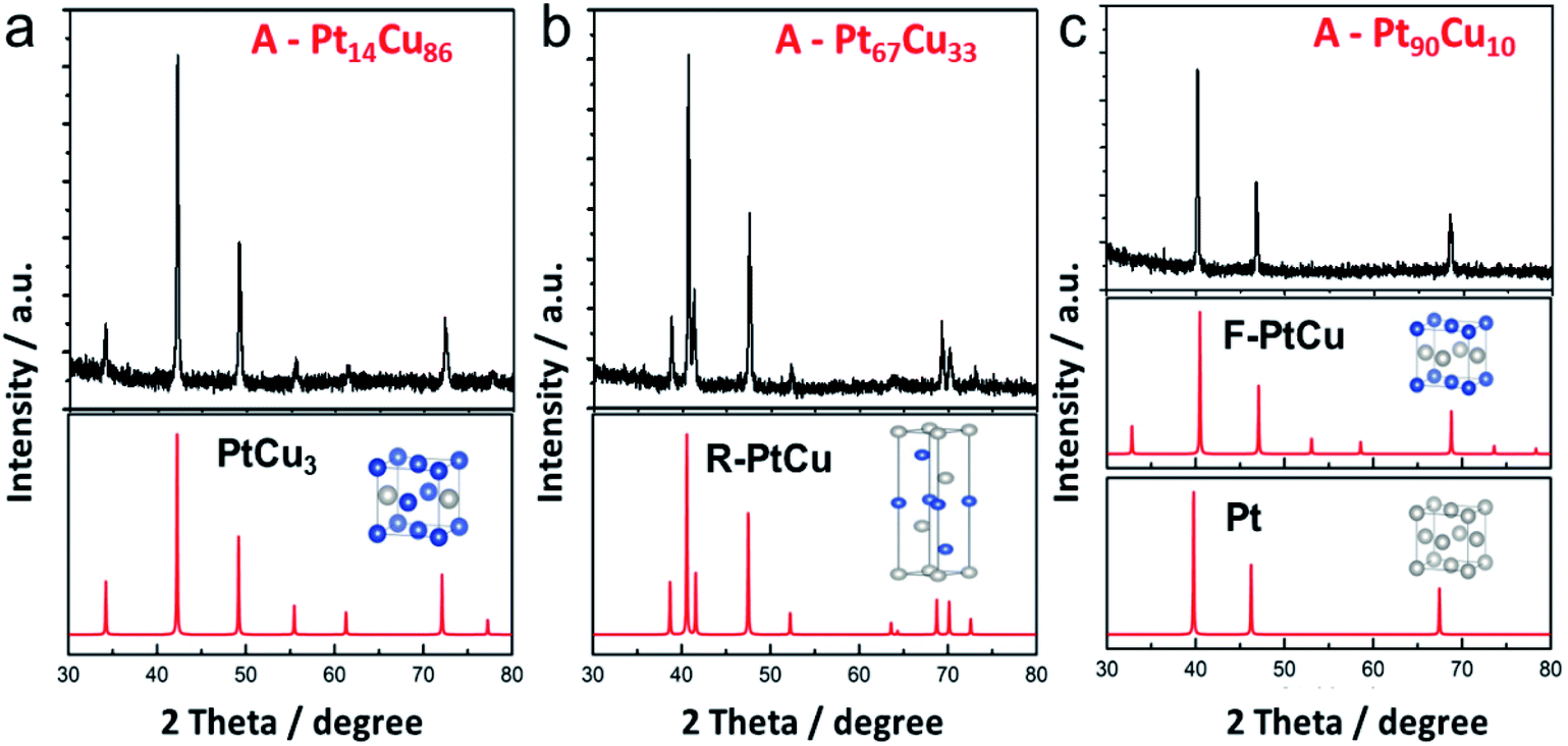 | ||
| Fig. 3 XRD patterns (black) and the corresponding calculated profiles (red) of (a) A-Pt14Cu86, (b) A-Pt67Cu33, (c) and A-Pt90Cu10 after annealing at 800 °C. The inset images present the unit cell structures; the blue and gray balls correspond to Cu and Pt atoms, respectively. | ||
To further explore the transformations of the valence states and surface compositions after annealing, XPS was used to analyze samples of bimetallic Pt67Cu33 and the alloy A-Pt67Cu33 after annealing. Both samples contain Pt, Cu, C and O elements in the survey spectra (Fig. S12†). The emergence of extra C species implies the existence of some impurities in the resultant products, and O is attributed to oxidation. Fig. 4a shows both high resolution Cu 2p spectra; typical binding energies of 932.0 eV and 952.2 eV simultaneously exist in both spectra, which can be assigned to Cu 2p3/2 and Cu 2p1/2 peaks from Cu0 or Cu(I) species, respectively. Pt67Cu33 shows additional peaks at binding energies of 934.2 eV and 954.8 eV, corresponding to CuO species, and peaks at 943.2 eV and 963.4 eV corresponding to satellite peaks, which are induced as a function of Cu(II) vibration due to excitation.48 Compared to the PtCu alloy structure, before annealing, the monometallic Cu surface is easily oxidized to form CuO. Similarly, small peaks from oxidized Pt at 72.0 eV and 77.1 eV emerge before the annealing of Pt (as shown in the high resolution XPS spectra in Fig. 4b). This demonstrates that bimetallic structures are relatively unstable, while alloys are more stable under open-air conditions. Clear 0.3 eV positive shifts of the Pt 4f7/2 peak from 71.1 to 71.4 eV and the Pt 4f5/2 peak from 74.5 to 74.8 eV are observed after annealing; such enhanced binding energy indicates the formation of an alloy structure.46
 | ||
| Fig. 4 (a) Cu 2p and (b) Pt 4f XPS spectra of both Pt67Cu33 nanowires and annealed A-Pt67Cu33. | ||
Using the various bimetallic and alloy structures with different compositions, the electrochemical performances of the samples were further investigated. The first cycle CV profiles before and after annealing in 0.1 M HClO4 solution were collected and are shown in Fig. 5. Typical H-adsorption/desorption peaks (−0.24 to 0.1 V) are observed from the bimetallic PtCu NWs. The annealed A-PtCu structures show no significant H-adsorption/desorption peaks; however, the profiles change in the ranges of 0–0.1 V and 0.2–0.6 V in the cases of the A-PtCu nanostructures with different compositions, separately corresponding to Cu dissolution and Pt oxidation/reduction.46 From the CV patterns, the presence of bimetallic PtCu nanowires with superficial Pt nanoparticles is further confirmed. The first cycle in HClO4 solution displays standard H-adsorption/desorption peaks at −0.24 to 0.1 V and Pt(111) peaks at 0.2–0.6 V.49 The H-adsorption/desorption peak intensities gradually get stronger as the Pt content increases. After 100 cycles of durability testing in HClO4 solution (Fig. S13†), bimetallic PtCu suffered surface restructuring accompanied by CV profile transformation.16 H-adsorption/desorption peaks at −0.24 to 0.1 V exist for all six PtCu nanowire samples, but the overlapping peak near the H-adsorption/desorption peak, which corresponds to Pt(100) oxidation/reduction, disappears in the case of the low Pt content sample Pt14Cu86 and gradually emerges as the Pt content increases. A similar phenomenon is seen in the range of 0.2–0.6 V, corresponding to Pt(111) oxidation/reduction.
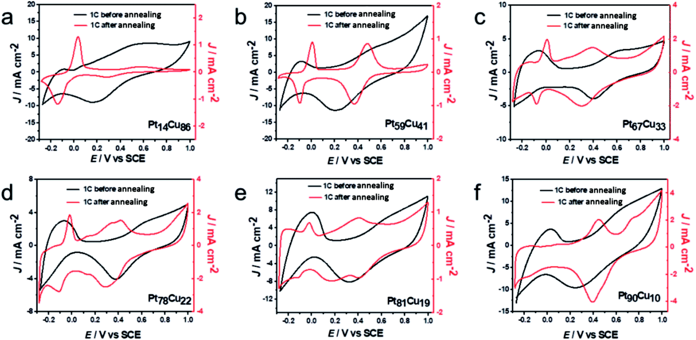 | ||
| Fig. 5 First cycle CV curves of (a) Pt14Cu86, (b) Pt59Cu41, (c) Pt67Cu33, (d) Pt78Cu22, (e) Pt81Cu19 and (f) Pt90Cu10 before and after annealing, obtained in 0.1 M HClO4 solution. | ||
In Fig. 5, after annealing, the first CV profiles of the A-PtCu samples changed drastically. Attributable to the alloy PtCu nanostructure, typical Cu oxidation/reduction peaks in the potential range of −0.2 to 0.1 V can be observed for the high Cu content samples. The reversible redox behavior implies a dealloying process and the reconstruction of the catalyst surface.49 As the Pt content increases, the peaks from Cu gradually become weaker and disappear in the case of A-Pt90Cu10, and the Pt oxidation/reduction peaks in the range of 0.2–0.6 V get stronger compared to the low Pt content alloy A-PtCu structures. Subsequent durability tests were carried out, and the results are shown in Fig. S14.† Standard Pt CV patterns were observed after 100 cycles. The intensities of the H-adsorption/desorption peaks are enhanced with an increase in the Pt content in A-PtCu. CV tests manifested the connection between bimetallic and alloy nanostructures with different compositions, which may provide useful information for designing new catalyst structures. The electrochemically active surface areas (ECSAs) of alloy and bimetallic PtCu nanostructures with different compositions are shown in Fig. S15.† The ECSA can be calculated via integrating the region of H-adsorption/desorption voltammetric wave charge, and further dividing by 0.21 mC cm−2 and the mass of Pt on the working electrode.46 The bimetallic PtCu nanowires have higher ECSAs compared to the alloy nanostructures (Fig. S15†). Bimetallic Pt14Cu86, Pt59Cu41, Pt67Cu33, Pt78Cu22, Pt81Cu19 and Pt90Cu10 have ECSA values of 118.6, 104.8, 102.7, 75.2, 70.1, and 67.3 m2 g−1, respectively, 1.54, 1.36, 1.33, 0.98, 0.91 and 0.88 times that of a commercial Pt electrocatalyst (76.8 m2 g−1). After annealing, the ECSA values significantly decrease to 28.4, 23.6, 26.8, 30.9, 22.8, and 41.1 m2 g−1, 0.37, 0.31, 0.35, 0.40, 0.30, and 0.54 times that of commercial Pt. The higher ECSA values were attributable to the small Pt nanoparticles on the bimetallic PtCu nanowire surfaces, even at low Pt content values. In contrast, the irregular and larger particles formed after annealing resulted in low ECSA values.24
To further acquire more information about the effects of such distinct structures and compositions on electrocatalysis, we studied both the bimetallic and alloy PtCu structures during direct methanol fuel cell energy conversion. The catalytic properties in 0.1 M HClO4 + 0.5 M CH3OH solutions were tested via CV and typical curves are shown in Fig. 6. Because of the various morphologies and crystal structures, the bimetallic and alloy PtCu samples with different compositions display different performances during methanol electrooxidation. As show in Fig. 6a, A-Pt14Cu86 possess the highest specific activity (9.26 mA cm−2), and A-Pt90Cu10, A-Pt67Cu33, and Pt14Cu86 show activities of 2.92 mA cm−2, 1.34 mA cm−2, and 0.7069 mA cm−2, respectively; these values are about 8.49, 2.67, 1.23 and 0.68 times that of commercial Pt/C (1.09 mA cm−2). A comparison of the specific activities of different compositions of PtCu before and after annealing is shown in Fig. 6b. The MOR specific activities of the annealed products are generally higher than those of the bimetallic structures. We hypothesize that neighboring Pt and Cu atoms might create a synergetic effect, where the Cu atoms near Pt at a negative potential absorbed oxygenated species (OHads) and facilitated lateral Pt–COads analogue oxidation.38 They might also create lattice strain effects for intermediate adsorption and surface ligand effects, which can result in an electrical environment change, further influencing MOR catalysis.21 The MOR properties of the alloy PtCu structures changed as the lattice length varied, as shown in Fig. 3. From MOR CV testing, A-Pt14Cu86 with a cubic structure (a = 3.702 Å) exhibits better catalytic properties compared to other structures, as a shorter binding length can better catalyze methanol oxidation. In contrast, R-centered hexagonal cubic A-Pt59Cu41, A-Pt67Cu33 and A-Pt78Cu22 with unstable structures show poor properties. This demonstrates that the MOR properties largely depend on the lattice length; shorter and more stable bond lengths could better impart a synergetic effect from Cu atoms, which were the activity site for further oxide intermediates, such as CO, HCOO− and HCO−. For the bimetallic structures, PtCu with different compositions and Pt/C showed similar specific activities; the independent Cu nanowires only play a template function and do not serve as sites to facilitate a synergetic effect.
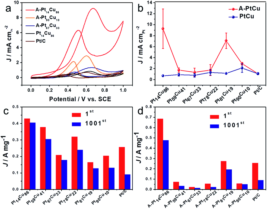 | ||
| Fig. 6 (a) CV curves of A-Pt14Cu86, A-Pt90Cu10, A-Pt67Cu33, Pt14Cu86 and Pt/C in 0.1 M HClO4 + 0.5 M CH3OH solution. (b) The specific activities of PtCu with different compositions before and after the annealing process. A comparison of the mass activities after the 1st cycle and 1001st cycle for PtCu with different compositions (c) before and (d) after annealing. | ||
CO poisoning is an important parameter when evaluating the properties of Pt-based catalysts; the relevant stripping tests were performed and the results are shown in Fig. S19.† After 20 min of CO being purged to the system, the gas was absorbed on the electrode and subsequent CV tests were performed to monitor this process. A typical CO oxidation peak can be observed in the first cycle and it disappears in the following cycle for both the bimetallic and alloy PtCu structures. However, the potential of CO oxidation changed depending on the PtCu composition and structure. As seen in Table S4,† the bimetallic PtCu nanostructures generally show a more negative potential of around 0.5 V compared with other samples, including Pt/C (0.548 V). Also, A-Pt14Cu86, A-Pt81Cu19 and A-Pt90Cu10 present more negative potentials of 0.511 V, 0.541 V, and 0.544 V, respectively, relative to Pt/C, with A-Pt59Cu41 (0.663 V), A-Pt67Cu33 (0.605 V) and A-Pt78Cu22 (0.631 V) showing more positive potential values. A weak CO binding energy on Pt can effectively reduce the oxidation potential and protect the Pt catalyst. These results confirm the perfect CO poisoning of the bimetallic structures made of small Pt nanoparticles on Cu nanowires, and also demonstrate the poor anti-poisoning of R-centered hexagonal cubic structures compared with the face centric cubic alloy structure. The above conclusions could provide more information relating to PtCu electrocatalyst durability for further analysis.
Next, durability testing of the MOR catalysts was implemented over 1000 cycles, and the corresponding CV curves are shown in Fig. S17 and S18.† The mass activities of the catalysts before and after 1000 cycles are summarized in Fig. 6c, d and Tables S5 and S6.† Bimetallic Pt14Cu86 (429.6 mA mg−1), Pt59Cu41 (378.6 mA mg−1), Pt67Cu33 (208.21 mA mg−1), Pt78Cu22 (319.8 mA mg−1), Pt81Cu19 (164.4 mA mg−1) and Pt90Cu10 (204.4 mA mg−1) show activities 1.67, 1.47, 0.81, 1.24, 0.64 and 0.79 times as high as that of commercial Pt (0.257 A mg−1), respectively. The corresponding annealed alloy products possess activities of 685.5, 72.8, 22.4, 54.9, 274.5 and 57.7 mA mg−1, respectively, which are about 2.67, 0.28, 0.09, 0.21, 1.07, and 0.22 times that of commercial Pt/C, respectively. A-Pt14Cu86 possesses the highest mass activity, and the R-centered hexagonal cubic alloy PtCu structures show poor mass activity compared to the other structures and compositions. Attributed to the advantage of the high activity surface of small Pt nanoparticles on the Cu nanowires, the bimetallic PtCu samples generally possess high mass activity. From the histograms shown in Fig. 6c and d, bimetallic Pt14Cu86, Pt59Cu41, Pt67Cu33, Pt78Cu22, Pt81Cu19 and Pt90Cu10 retain higher current density percentages of about 94.6, 80.6, 85.4, 75.0, 77.3 and 64.9% of their original activities, respectively, compared to the corresponding annealed A-PtCu samples, which retain 69.4, 45.1, 59.4, 41.0, 70.7, and 84.6% of their original activities. As a baseline, commercial Pt/C only retains 35% of its initial activity after 1000 cycles of CV testing (Fig. S16†). Most of our synthesized PtCu catalysts possess better durability during methanol oxidation than commercial Pt/C. The stability properties of the catalysts have an intimate connection with the corresponding CO anti-toxicity performances. The R-centered hexagonal crystals of Pt59Cu41, Pt67Cu33, and Pt78Cu22 show poor stability, and their CO oxidation potentials are generally positive compared to the other structures, indicating strong CO bonds with the metallic portion of the unstable crystal structure, quickly resulting in the degradation of the catalyst. The histograms clearly show that the bimetallic structures typically maintain higher stability compared to the other structures. As mentioned earlier, the alloys have better performance in terms of MOR catalysis initially. But as the electrocatalysis process continues, the bimetallic structure undergoes interior atom restructuring, i.e., Pt14Cu86 has higher CO anti-toxicity, which can better protect the Pt catalyst to achieve better stability. Besides, compared with the easily aggregated nanoparticles of the alloy structures, the nanowire morphology of bimetallic PtCu could better maintain the MOR properties over long periods of testing.
In addition, based on the density functional theory (DFT) method, we theoretically studied the catalytic activities of the catalyst during the methanol oxidation reaction (MOR) at different Pt–Cu ratios and with different crystal structures. By plotting the Gibbs free energy profile, the decisive step and overpotential of the MOR can be determined. Corresponding to the bimetallic samples with different Pt–Cu ratios used in experiments, we constructed four structures, Pt, R-PtCu, F-PtCu and PtCu3, and their simulated XRD patterns matched the test data well, as shown in Fig. 3. Previous studies have shown that the {110} surface of Pt is more active during the methanol electrooxidation reaction,50 so here we chose the {110} surface to compare the activities of the above-mentioned four structures during the MOR, as shown in Fig. S20.† Based on a previous report,40 we chose three possible reaction pathways, path 1 (via a COOH intermediate), path 2 (via a HCO intermediate) and path 3 (via a COH intermediate), and each reaction path contains six electron transfer steps, as shown in Fig. 7a and Table S7.† On the {110} surface of Pt, the MOR along path 1 seems to require a lower overpotential than path 2 and path 3, which means that path 1 is likely to be dominant for the MOR. Therefore, we chose path 1 as our basis and continued to study the effects of different Pt–Cu ratios and crystal structures on methanol electrooxidation. As shown in Fig. 7b, for Pt and PtCu3, the last step, COOH* → CO2+* + H+ + e−, is the rate-determining step in the MOR, and the corresponding overpotentials are 0.435 and 0.245 eV, respectively; however, for F-PtCu and R-PtCu, water splitting is the rate-determining step. The overpotentials of F-PtCu and R-PtCu are close: 0.325 and 0.345 eV, respectively. More detailed data can be found in Tables S8 and S9 in the ESI.† The above calculation results show that the greater the amount of Cu, the better the catalytic performance. At a ratio of 1![[thin space (1/6-em)]](https://www.rsc.org/images/entities/char_2009.gif) :1, F-PtCu is slightly better than R-PtCu. The results from the DFT simulations are consistent with the experiments.
:1, F-PtCu is slightly better than R-PtCu. The results from the DFT simulations are consistent with the experiments.
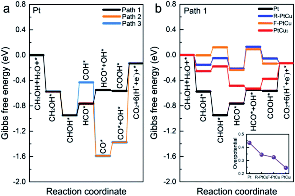 | ||
| Fig. 7 (a) Free energy diagrams of methanol electrooxidation along path 1 (via a carboxyl intermediate), path 2 (via an aldehyde intermediate), and path 3 (via a COH intermediate) using Pt under standard conditions. (b) The free-energy potential surfaces for methanol electrooxidation on Pt, R-PtCu, F-PtCu and PtCu3via path 1. The inset shows the overpotentials of Pt, R-PtCu, F-PtCu and PtCu3. | ||
Systematic electrochemical tests provided reliable information for exploring the relative properties connected with the microstructures. Bimetallic and alloy PtCu structures generally display outstanding MOR properties. In addition, it is evident that the MOR properties strongly depend on the combination/arrangement of Pt and Cu atoms and the corresponding lattice structures. When Cu and Pt atoms strongly combine with each other, forming an alloy,22 synergetic effects help to absorb oxygenated species (OHads) to facilitate Pt–COads analogue oxidation, improving the MOR properties. Typically, the alloy structure A-Pt14Cu86 with a cubic structure (a = 3.702 Å) has the best MOR catalytic activity (9.26 mA cm−2), which is about 8.49 times that of commercial Pt/C. Further DFT calculations were used to determine the overpotentials of Pt, R-PtCu, F-PtCu and PtCu3 (0.435 eV, 0.345 eV, 0.325 eV and 0.245 eV, respectively), which could better illustrate the dependent relationship between the specific lattice structure and the corresponding MOR properties. However, the synergetic effects primarily influence the initial catalytic process. After a de-alloying process, the surface atoms rearranged and bimetallic structures with high Cu content showed better anti-toxicity, as indicated by CO stripping testing to evaluate CO poisoning, and excellent stability during MOR electrooxidation. These results show promise for exploring tunable electrocatalysts and constructing desirable catalyst architectures for many potential applications with high performance and durability.
4. Conclusions
In summary, we have demonstrated an approach using Cu nanowires as templates to synthesize PtCu nanostructures with controllable compositions using ascorbic acid as a reductant. A subsequent annealing process resulted in the nanostructural transformation of samples with different compositions. The morphological and structural transformations occurring in bimetallic and alloy forms are manifested through CV testing. The insertion of a second metal into both bimetallic and alloy structures could enhance the methanol electrooxidation performance in terms of generating a high specific activity current, high CO tolerance and better stability. Alloy PtCu nanostructures have enhanced MOR activities compared to bimetallic structures in the initial catalytic process, in which Cu atoms near Pt at a negative potential could better absorb oxygenated species (OHads) to facilitate Pt–COads analogue oxidation. Typically, from analysis of the test results, free energy paths and calculated overpotentials, the Cu-rich alloy structure of A-Pt14Cu86 exhibited the highest methanol oxidation activity and showed the intimate correlation between the lattice structure and corresponding properties of the catalyst. During long-term catalyst durability testing, the bimetallic structures showed great anti-toxicity toward CO and associated catalyst stability. The synthesized catalysts and systemic investigations implemented in this study are not limited to the MOR but also have great potential for other catalytic applications, for instance the ORR, GOR, etc. Catalysts persistently play a crucial role in providing access to clean energy, and the systematic and integrated data obtained in this work from different PtCu structures might suggest rational approaches toward catalyst design to further boost corresponding performances. Various structures of congeneric products could clearly provide comparative data to gain a better understanding of electrocatalytic mechanisms. This work will open new doors for constructing high performance and durable catalysts for the future development of fuel cells.Conflicts of interest
There are no conflicts to declare.Acknowledgements
S. L. acknowledges the National Natural Science Foundation of China with grant no. 21705036 and 21975067, the Natural Science Foundation of Hunan Province, China with grant no. 2018JJ3035, and Fundamental Research Funds for the Central Universities from Hunan University. Y. X. F. acknowledges the National Basic Research Programs of China with grant no. 2016YFA0300901 and the National Science Foundation of China with grant no. 11974105. G. Y. acknowledges the National Natural Science Foundation of China with grant no. 21476066 and 51271074. T. S. H. acknowledges support from the U.S. National Science Foundation CREST program with grant No. NSF HRD-1547723.References
- S. Wang, S. P. Jiang, T. J. White, J. Guo and X. Wang, J. Phys. Chem. C, 2009, 113, 18935–18945 CrossRef CAS.
- J. Ying, G. Jiang, Z. P. Cano, Z. Ma and Z. Chen, Appl. Catal., B, 2018, 236, 359–367 CrossRef CAS.
- C. Li, M. Iqbal, B. Jiang, Z. Wang, J. Kim, A. K. Nanjundan, A. E. Whitten, K. Wood and Y. Yamauchi, Chem. Sci., 2019, 10, 4054–4061 RSC.
- B. Singh, L. Murad, F. Laffir, C. Dickinson and E. Dempsey, Nanoscale, 2011, 3, 3334–3349 RSC.
- F. Wu, J. Lai, L. Zhang, W. Niu, B. Lou, R. Luque and G. Xu, Nanoscale, 2018, 10, 9369–9375 RSC.
- L. Lu, S. Chen, S. Thota, X. Wang, Y. Wang, S. Zou, J. Fan and J. Zhao, J. Phys. Chem. C, 2017, 121, 19796–19806 CrossRef CAS.
- C. Li, H. Tan, J. Lin, X. Luo, S. Wang, J. You, Y.-M. Kang, Y. Bando, Y. Yamauchi and J. Kim, Nano Today, 2018, 21, 91–105 CrossRef CAS.
- J. Solla-Gullón, F. J. Vidal-Iglesias, A. López-Cudero, E. Garnier, J. M. Feliu and A. Aldaz, Phys. Chem. Chem. Phys., 2008, 10, 3689–3698 RSC.
- W. Chrzanowski and A. Wieckowski, Langmuir, 1998, 14, 1967–1970 CrossRef CAS.
- C. Li, M. Iqbal, J. Lin, X. Luo, B. Jiang, V. Malgras, K. C. W. Wu, J. Kim and Y. Yamauchi, Acc. Chem. Res., 2018, 51, 1764–1773 CrossRef CAS PubMed.
- H. Ataee-Esfahani, Y. Nemoto, L. Wang and Y. Yamauchi, Chem. Commun., 2011, 47, 3885–3887 RSC.
- A. Funatsu, H. Tateishi, K. Hatakeyama, Y. Fukunaga, T. Taniguchi, M. Koinuma, H. Matsuura and Y. Matsumoto, Chem. Commun., 2014, 50, 8503–8506 RSC.
- F. Saleem, Z. Zhang, B. Xu, X. Xu, P. He and X. Wang, J. Am. Chem. Soc., 2013, 135, 18304–18307 CrossRef CAS PubMed.
- S. Guo, S. Dong and E. Wang, ACS Nano, 2010, 4, 547–555 CrossRef CAS PubMed.
- Y. Li, W. Gao, L. Ci, C. Wang and P. M. Ajayan, Carbon, 2010, 48, 1124–1130 CrossRef CAS.
- L. Jacobse, Y.-F. Huang, M. T. M. Koper and M. J. Rost, Nat. Mater., 2018, 17, 277–282 CrossRef CAS PubMed.
- R. M. Crooks and M. Zhao, Adv. Mater., 1999, 11, 217–220 CrossRef.
- S. Alayoglu, A. U. Nilekar, M. Mavrikakis and B. Eichhorn, Nat. Mater., 2008, 7, 333 CrossRef CAS PubMed.
- H. Gao, F. Xiao, C. B. Ching and H. Duan, ACS Appl. Mater. Interfaces, 2011, 3, 3049–3057 CrossRef CAS PubMed.
- R. Loukrakpam, J. Luo, T. He, Y. Chen, Z. Xu, P. N. Njoki, B. N. Wanjala, B. Fang, D. Mott, J. Yin, J. Klar, B. Powell and C.-J. Zhong, J. Phys. Chem. C, 2011, 115, 1682–1694 CrossRef CAS.
- J. A. Wittkopf, J. Zheng and Y. Yan, ACS Catal., 2014, 4, 3145–3151 CrossRef CAS.
- D. Li, K. Cai, L. Wu, Y. Zuo, W. Yin, H. Zhang, Z. Lu, G. Zhu and H. Han, ACS Sustainable Chem. Eng., 2017, 5, 11086–11095 CrossRef CAS.
- K. A. Kuttiyiel, K. Sasaki, Y. Choi, D. Su, P. Liu and R. R. Adzic, Nano Lett., 2012, 12, 6266–6271 CrossRef CAS PubMed.
- B. Y. Xia, H. B. Wu, X. Wang and X. W. Lou, J. Am. Chem. Soc., 2012, 134, 13934–13937 CrossRef CAS PubMed.
- H. Yang, L. Dai, D. Xu, J. Fang and S. Zou, Electrochim. Acta, 2010, 55, 8000–8004 CrossRef CAS.
- W. Hong, J. Wang and E. Wang, Small, 2014, 10, 3262–3265 CrossRef CAS PubMed.
- W. Hong, J. Wang and E. Wang, Nano Res., 2015, 8, 2308–2316 CrossRef CAS.
- H. J. Qiu, X. Shen, J. Q. Wang, A. Hirata, T. Fujita, Y. Wang and M. W. Chen, ACS Catal., 2015, 5, 3779–3785 CrossRef CAS.
- H. J. Qiu, H. T. Xu, X. Li, J. Q. Wang and Y. Wang, J. Mater. Chem. A, 2015, 3, 7939–7944 RSC.
- Z. Zhang, Z. Luo, B. Chen, C. Wei, J. Zhao, J. Chen, X. Zhang, Z. Lai, Z. Fan, C. Tan, M. Zhao, Q. Lu, B. Li, Y. Zong, C. Yan, G. Wang, Z. J. Xu and H. Zhang, Adv. Mater., 2016, 28, 8712–8717 CrossRef CAS PubMed.
- S. B. Barim, S. E. Bozbag, H. Yu, R. Kızılel, M. Aindow and C. Erkey, Catal. Today, 2018, 310, 166–175 CrossRef CAS.
- X. Lu, M. McKiernan, Z. Peng, E. P. Lee, H. Yang and Y. Xia, Sci. Adv. Mater., 2010, 2, 413–420 CrossRef CAS.
- M. Mohl, D. Dobo, A. Kukovecz, Z. Konya, K. Kordas, J. Wei, R. Vajtai and P. M. Ajayan, J. Phys. Chem. C, 2011, 115, 9403–9409 CrossRef CAS.
- M. Xiao, S. Li, X. Zhao, J. Zhu, M. Yin, C. Liu and W. Xing, ChemCatChem, 2014, 6, 2825–2831 CrossRef CAS.
- E. Taylor, S. Chen, J. Tao, L. Wu, Y. Zhu and J. Chen, ChemSusChem, 2013, 6, 1863–1867 CrossRef CAS PubMed.
- X. Huang, Y. Chen, E. Zhu, Y. Xu, X. Duan and Y. Huang, J. Mater. Chem. A, 2013, 1, 14449–14454 RSC.
- Y. Huang, J. Cai, S. Zheng and Y. Guo, J. Power Sources, 2012, 210, 81–85 CrossRef CAS.
- Y. Liao, G. Yu, Y. Zhang, T. Guo, F. Chang and C.-J. Zhong, J. Phys. Chem. C, 2016, 120, 10476–10484 CrossRef CAS.
- H. Xiang, T. Guo, M. Xu, H. Lu, S. Liu and G. Yu, ACS Appl. Nano Mater., 2018, 1, 3754–3759 CrossRef CAS.
- L. Huang, W. Zhang, P. Li, Y. Song, H. Sheng, Y. Du, Y.-G. Wang, Y. Wu, X. Hong, Y. Ding, X. Yuan and M. Zhu, Nano Res., 2019, 12, 1147–1153 CrossRef CAS.
- G. Kresse and J. Furthmüller, Comput. Mater. Sci., 1996, 6, 15–50 CrossRef CAS.
- J. P. Perdew, K. Burke and M. Ernzerhof, Phys. Rev. Lett., 1996, 77, 3865–3868 CrossRef CAS PubMed.
- J. K. Nørskov, J. Rossmeisl, A. Logadottir, L. Lindqvist, J. R. Kitchin, T. Bligaard and H. Jónsson, J. Phys. Chem. B, 2004, 108, 17886–17892 CrossRef.
- D. R. Lide, Handbook of Chemistry and Physics, 2004–2005 Search PubMed.
- M. Oezaslan, F. Hasché and P. Strasser, Chem. Mater., 2011, 23, 2159–2165 CrossRef CAS.
- I. A. Khan, Y. Qian, A. Badshah, D. Zhao and M. A. Nadeem, ACS Appl. Mater. Interfaces, 2016, 8, 20793–20801 CrossRef CAS PubMed.
- C. Li, T. Liu, T. He, B. Ni, Q. Yuan and X. Wang, Nanoscale, 2018, 10, 4670–4674 RSC.
- C. Yang, C. Zhang and L. Liu, J. Mater. Chem. A, 2018, 6, 20992–21002 RSC.
- S. Koh and P. Strasser, J. Am. Chem. Soc., 2007, 129, 12624–12625 CrossRef CAS PubMed.
- T. H. M. Housmans, A. H. Wonders and M. T. M. Koper, J. Phys. Chem. B, 2006, 110, 10021–10031 CrossRef CAS PubMed.
Footnotes |
| † Electronic supplementary information (ESI) available. See DOI: 10.1039/d0na00076k |
| ‡ These authors contributed equally to this work. |
| This journal is © The Royal Society of Chemistry 2020 |