
 Open Access Article
 This Open Access Article is licensed under a Creative Commons Attribution-Non Commercial 3.0 Unported Licence
Synthesis of novel catalytic composite nanofibers containing ruthenium nanoparticles stabilized by a citric acid-β-cyclodextrin polymer
Sami
Fadlallah
ab,
Nicolas
Tabary
a,
Sébastien
Noël
 b,
Bastien
Léger
b,
Frédéric
Cazaux
a,
Eric
Monflier
b and
Bernard
Martel
*a
b,
Bastien
Léger
b,
Frédéric
Cazaux
a,
Eric
Monflier
b and
Bernard
Martel
*a
aUniv. de Lille, CNRS, ENSCL, UMR 8207, Unité Matériaux et Transformations (UMET), F-59650 Villeneuve d'Ascq, France. E-mail: bernard.martel@univ-lille.fr
bUniv. d'Artois, CNRS, Centrale Lille, ENSCL, Univ. de Lille, UMR 8181, Unité de Catalyse et Chimie du Solide (UCCS), F-62300 Lens, France
First published on 24th March 2020
Abstract
The elaboration of catalytic composite nanofibers (NFs) by electrospinning through a one-pot strategy is described. First, aqueous colloidal suspensions of ruthenium nanoparticles (Ru NPs) formed by reduction of a Ru(III) salt with NaBH4 and stabilized by poly(cyclodextrin citrate) (PCD) were prepared. Then, poly(vinyl alcohol) (PVA) of different molecular weights was dissolved in the colloidal suspensions that were electrospun. SEM analyses of the resulting nanowebs displayed uniform NFs, whose diameters ranged between 300 and 700 nm and enlarged upon increasing (i) PVA molecular weight, (ii) nanosuspension viscosity, (iii) the amount of NaBH4 and (iv) the PCD/Ru NP concentration. TEM analysis confirmed that Ru NPs with a mean diameter of around 2 nm were observed at the surface of NFs, embedded in the PVA matrix of NFs. HAADF-STEM and EDS mapping clearly showed that Ru NPs were homogeneously distributed onto and into the matrix of NFs. After their electrospinning, the prepared nanowebs were submitted to a heat post-treatment at 160 °C which was shown to trigger the PVA crystallization. In addition, the physical crosslinking of PVA chains by NaBO2 resulting from NaBH4 oxidation in the precursor suspension was also observed. Interestingly, an SEM study evidenced that the thermal post-treatment in combination with the presence of NaBO2 clearly improved the thermal stability of the synthesized composite nanowebs. Finally, catalytic hydrogenation tests showed the absence of Ru NPs leaching from NFs in the reaction medium, and displayed good conversion of styrene into ethylbenzene.
Introduction
Discovered and patented at the beginning of the XXth century,1 electrospinning is a simple and versatile technique used to produce nanofibers (NFs) from melt polymers or most frequently from polymer solutions flowing through a nozzle (emitter) and forming a jet resulting from electrostatic forces induced by an electric field applied between the emitter and the collector surface.2,3 The morphology of nanofibers can be controlled by regulating instrument settings (the type of nozzle, injection speed, tip-to-collector distance), solution parameters (molecular weight, concentration, viscosity, solvent, conductivity, etc.) and atmosphere conditions (mainly temperature and relative humidity). Electrospun NFs can be composed of a single polymer, mixed polymers or organic/inorganic components. Composite NFs constitute a class of materials possessing unique chemical and physical properties which offer them significant potential in various fields such as tissue engineering, drug delivery and optical sensors.4,5The fabrication of nanofibrous networks, based on a blend of polymers, by the electrospinning technique, has been widely reported during the last two decades.6,7 In particular, the preparation of functional nanofibers made of organic polymers such as poly(vinyl alcohol) (PVA), poly(vinyl pyrrolidone) (PVP) or poly(acrylonitrile) (PAN) with the incorporation of metal nanoparticles (NPs), such as Ag and Au, has recently attracted great attention8–12 and could find applications in diverse fields, such as catalysis, medicine, optics, microelectronics and sensing.13–15 They are defined by their high surface area of active metals, which means (i) a large fraction of surface-exposed metal atoms and (ii) a high number of edges at which reactions can take place.
Generally, there are two common synthetic strategies reported for the production of these types of materials. The first one consists of a two-step process: (i) electrospinning of a solution containing a metal salt with a polymer followed by (ii) the reduction of the metal salt inside the NFs to form metal NPs.16 The other one consists of the preparation of the nanofibers and dipping them in a metal precursor solution followed by its chemical reduction in order to form the metal NPs.17 According to the literature survey, several efficient methods for the production of nanofibers incorporating metal NPs are referenced. For instance, the one-step synthesis of polyethylene oxide18 or polyvinyl alcohol19 nanofibers containing Ag NPs was reported where the polymer solution was used not only as an electrospinnable agent but also as a reducing and stabilizing agent for the synthesis of Ag NPs. Moreover, composite nanofibers of β-cyclodextrin (β-CD)/PVP comprising Au NPs were prepared. In this study, they added β-CD as a new material which acted as a protective and reducing agent in the synthesis of Au NPs.20 Nevertheless, none of these publications are dedicated to catalytic applications. Only very recently, Uyar et al.21 reported the synthesis of a carbon nanofiber-supported Ru NP composite material by combining two fabrication methods: electrospinning and atomic layer deposition. This catalytic system was used for the dehydrogenation of methylamine borane and was found to be a nearly non-leaching catalytic system and conserved 72% of its activity after five consecutive cycles. But it should be noticed that in this case, in addition to the atomic layer deposition and electrospinning technique, the synthesis of these composite materials required a carbonization step and consequently, all of this synthesis process was not so easy to set up. Moreover, atomic layer deposition is not adaptable to the development of heterogeneous catalysts on a large scale. The same team also developed the atomic layer deposition of Pd NPs onto functional electrospun poly-cyclodextrin nanowebs for the catalytic reduction of 4-nitrophenol.22 Moreover, the same group has also reported the elaboration of nanocomposite polymer free hydroxypropyl-β-CD (HP-β-CD) NFs prepared by the electrospinning of HP-β-CD from aqueous and DMF solutions containing two different Pd concentrations where HP-β-CD played a reducing agent role in order to produce Pd NPs.23 TEM images displayed uniform Pd NPs homogeneously distributed in the nanofiber matrix with a mean particle size varying between 3.7 and 4.9 nm depending on the solvent and Pd loading. These composite materials were used for the catalytic reduction of 4-nitrophenol into 4-aminophenol in the presence of an excess of sodium borohydride. Surprisingly, none of these composite nanomaterials were used for the catalytic hydrogenation of hydrophobic unsaturated compounds under hydrogen.
In this context, according to our previous work on the stabilization of ruthenium NPs by poly(citric acid-β-cyclodextrin) (PCD) and their use for the catalytic hydrogenation of biosourced substrates, this kind of ruthenium colloidal suspension24 was converted into supported catalytic systems by using the electrospinning technique. Therefore, our strategy was to dissolve polyvinylalcohol (PVA) in the aqueous nanosuspension and electrospin the resulting mixture (Fig. 1), which yielded NFs with the PVA matrix enclosing dispersed PCD/Ru NPs. To the best of our knowledge, a one-pot strategy for the fabrication of NFs carrying Ru NPs starting from a Ru salt has never been previously described and they have not been proved to be catalytically active in the hydrogenation of styrene.
 | ||
| Fig. 1 Processing steps for the preparation of PVA/PCD/Ru NP NFs. | ||
Experimental
General
Ru(NO)(NO3)3 solution (1.5 wt% Ru) was purchased from STREM Chemicals. Sodium borohydride and citric acid were provided by Acros Organics, and sodium hydrogenocarbonate by Aldrich Chemicals (Saint Quentin-Fallavier, France), and they were used without any further purification. Poly(citric acid-β-cyclodextrin), PCD, was synthesized by polyesterification in the presence of citric acid according to a previously reported procedure.25 Poly(vinyl alcohol), PVA, was purchased from Aldrich Chemicals, 87–89% hydrolyzed, LMW = 31–50 kg mol−1, MMW = 85–124 kg mol−1 and HMW = 146–186 kg mol−1 (respectively named LMW-PVA, MMW-PVA and HMW-PVA), and used as received. Purified deionized water was purchased from Fresenius Kabi.Synthesis of colloidal PCD/Ru NP solution
In a typical experiment,24 the colloidal suspension was prepared as follows at ambient temperature: 114 mg of PCD (MW = 25![[thin space (1/6-em)]](https://www.rsc.org/images/entities/char_2009.gif) 500 g mol−1, 3.5 mmol g−1 COOH acidic sites, i.e. 400 μmol of acidic sites) was dissolved in 5 mL of deionized water in the presence of a controlled amount of NaHCO3 (molar ratio of NaHCO3 to COOH = 1.1) and the mixture was kept under vigorous stirring for 3 h. Then 269 mg of an aqueous solution of Ru(NO)(NO3)3 (1.5 wt% Ru) (40 μmol, 1 equiv.) were dispersed in 3 mL of deionized water. Both solutions were mixed together under vigorous stirring for 30 min. Then, 15.2 mg of NaBH4 (400 μmol, 10 equiv.) previously dissolved in 4 mL of water was quickly added to the mixture. The resulting colloidal suspension was kept under vigorous stirring for 24 h before the addition of the PVA polymer.
500 g mol−1, 3.5 mmol g−1 COOH acidic sites, i.e. 400 μmol of acidic sites) was dissolved in 5 mL of deionized water in the presence of a controlled amount of NaHCO3 (molar ratio of NaHCO3 to COOH = 1.1) and the mixture was kept under vigorous stirring for 3 h. Then 269 mg of an aqueous solution of Ru(NO)(NO3)3 (1.5 wt% Ru) (40 μmol, 1 equiv.) were dispersed in 3 mL of deionized water. Both solutions were mixed together under vigorous stirring for 30 min. Then, 15.2 mg of NaBH4 (400 μmol, 10 equiv.) previously dissolved in 4 mL of water was quickly added to the mixture. The resulting colloidal suspension was kept under vigorous stirring for 24 h before the addition of the PVA polymer.
Several PCD/Ru NP suspensions were synthesized in situ in two successive steps.24 PCD (3.5 mmol g−1 acidic sites, 10 molar equivalents to Ru) was first solubilized in an aqueous solution of NaHCO3 with a molar ratio of NaHCO3:COOH = 1.1:1. The slight excess of NaHCO3 was to ensure the conversion of all carboxylic acid groups into the corresponding sodium carboxylate. The pH value reached 6.4 after 3 h of reaction time at room temperature. Ru(NO)(NO3)3 (with different concentrations: [Ru]0, 2[Ru]0, 4[Ru]0, thanks to the first material synthesized starting from 40 μmol of Ru solubilized in 3 mL, it means [Ru]0 = 13.33 mM) was added and the solution was stirred for 30 min. This step was followed by the reduction of Ru(III) by the addition of an excess of sodium borohydride (2.5, 5 or 10 equiv. with respect to the Ru salt) as a reducing agent which resulted in the formation of Ru NPs. Whatever the concentration of Ru or the molar quantity of sodium borohydride, no sedimentation of the nanosuspensions was observed.
Preparation of PVA/PCD/Ru NP suspension for electrospinning
In a typical experiment, the PCD/Ru colloidal suspension (2.5, 5 or 10 equiv. of NaBH4 was used as the reducing agent keeping constant the PCD, NaHCO3 and ruthenium amounts, i.e. respectively, 400 μmol, 440 μmol and 40 μmol) in 12 mL of water was heated at 80 °C. 960 mg of PVA (8 wt%, 31–50, 85–124 and 143–186 kg mol−1) was then added to this colloidal suspension consecutively in ten portions, at 80 °C, under constant stirring for a period of 4 h. The resulting colloidal suspension was visually stable for months and no sedimentation was observed (Table 1).| MMW-PVA NFs | MMW-PVA/NaBH4 NFs | MMW-PVA/PCD/Ru NP NFs | |
|---|---|---|---|
| a Equivalents based on [Ru]0. | |||
| PVA (8%wt/vol) | 960 mg | 960 mg | 960 mg |
|
|||
| NaBH 4 | |||
| 2.5 equivalents/Ru(III)a | 3.8 mg | 3.8 mg | |
| 5 equivalents/Ru(III)a | 7.6 mg | 7.6 mg | |
| 10 equivalents/Ru(III)a | 15.2 mg | 15.2 mg | |
| Stabilizing agent (PCD) | 124 mg | ||
|
|||
| Ru(NO)(NO 3 ) 3 | |||
| [Ru]0 | 269 mg | ||
| 2[Ru]0 | 538 mg | ||
| 4[Ru]0 | 1076 mg | ||
Electrospinning
The prepared solutions were loaded into 5 mL syringes connected to a 21-gauge metallic needle through a polyethylene catheter (inner diameter: 1 mm, Vygon, France) and positioned on the syringe pump. Aluminum foil pieces served as NF collectors. In a typical experiment, the electrospinning of the solution was performed using the following parameters: voltage: 20 kV, tip-to-collector distance: 25 cm and solution flow rate: 0.2 mL h−1. The electrospinning apparatus was enclosed in a Plexiglas box and the electrospinning was carried out at 22 °C ±2 °C and 40% ±5% relative humidity.Catalytic experiment
The hydrogenation experiment was performed using a Parker-Autoclave Engineers stainless steel autoclave containing the composite NFs in 12 mL of decane in a glass vessel. The mixture was heated up to 30 °C in a thermostated oil bath, the substrate was added and the reactor was purged three times with nitrogen, and hydrogen was fed to the system at a constant pressure of up to 10 bar. The reaction composition was determined by taking an aliquot of the reaction mixture and analyzing it by gas chromatography with a Varian 3900 gas chromatograph equipped with a CP-Sil-5B (30 m × 0.25 mm × 0.25 μm) and a flame ionization detector.Heat treatment
The electrospun nanofibers were stabilized by heating in a ventilated oven at 130, 160 and 190 °C for 2 h. These temperatures were selected as TGA experiments showed that the decomposition of PVA started above 200 °C and hence 190 °C was considered as an upper limit.Characterization
The viscosities of the electrospun solutions were measured at shear rates between 50 and 1000 s−1 by using a rheometer (Anton Paar Physica MCR 301) equipped with a plate/plate accessory (PP25, d = 25 mm) and a plate thermostated at 25 °C using a Peltier system. The morphology and diameter of the obtained nanofibers were analyzed using a scanning electron microscope (SEM) (Hitachi S-4700 SEM field emission GU) operating at an accelerating voltage of 3–5 kV and an emission current of 10 mA. Samples were sputtered beforehand with a thin layer of chrome. Transmission electron microscopy (TEM) was performed on a Tecnai microscope (200 kV). A sample of the nanofiber was suspended onto a carbon coated copper grid. Metal particle size distributions were determined from the measurement of around 200 particles found in an arbitrarily chosen area of the images using the program ImageJ. STEM (Scanning Transmission Electron Microscopy) in HAADF mode (High Annular Angle Dark Field) was performed on a Titan Themis microscope operating at 300 kV with a resolution of 0.7 Angstrom equipped with an EDS detector (superX Bruker). NF samples were immobilized between two carbon copper grids.Differential scanning calorimetry experiments were performed with a DSC Q100 calorimeter (TA Instruments). All the experiments were performed with a heating rate of 10 °C min−1. For all the experiments, the sample (∼5 mg) was positioned in an aluminum pan and was flushed with highly pure nitrogen gas (50 mL min−1). Temperature and enthalpy readings were calibrated using pure indium at the same scan rates and with the same kind of pan used in the experiments.
Results and discussions
Preparation of PVA/PCD/Ru NP suspensions
First, based on the strategy described before,24 a stable PCD/Ru nanosuspension was prepared in water and the next step consisted of the chemical reduction of ruthenium nitrosyl nitrate by an excess of sodium borohydride in the presence of a water soluble β-CD polymer crosslinked with citric acid (PCD). The preparation of NFs incorporating PCD/Ru NPs by electrospinning required the solubilization of an electrospinnable water-soluble polymer in the colloidal suspension. Hence, polyvinyl alcohol (PVA) was chosen as it is widely used for the preparation of nanofibers, and is used alone or mixed with other polymers such as poly(acrylic acid),26,27 poly(ethylene glycol), poly(isopropyl acrylamide), poly(vinyl pyrrolidone),28,29 chitosan, gelatin30,31 and cyclodextrin.32 PVA polymers of low molecular weight (LMW-PVA = 31–50 kg mol−1), medium molecular weight (MMW-PVA = 85–124 kg mol−1) and high molecular weight (HMW-PVA = 143–186 kg mol−1) were dissolved in the PCD/Ru nanosuspensions (8% wt/vol) and in pure water. Fig. 2 reports the viscosity of these solutions as a function of the shear rate. All curves presented almost stable viscosities in the 50–1000 s−1 shear rate range. | ||
Fig. 2 Viscosity (η) at a shear rate ![[small gamma, Greek, dot above]](https://www.rsc.org/images/entities/i_char_e0a2.gif) fixed at 200 s−1 for LMW, MMW and HMW-PVA dissolved in water and in PCD/Ru nanosuspensions (concentration of PVA = 8% w/v, 25 °C). fixed at 200 s−1 for LMW, MMW and HMW-PVA dissolved in water and in PCD/Ru nanosuspensions (concentration of PVA = 8% w/v, 25 °C). | ||
As can be seen in Fig. 2, viscosities at a shear rate of 200 s−1 of MMW-PVA and HMW-PVA polymer solutions were, respectively, 103 mPa s and 283 mPa s, while the LMW polymer solution has a viscosity of only 12.6 mPa s. When MMW-PVA and HMW-PVA polymers are added to the PCD/Ru colloidal suspension, an increase of the viscosity is observed with values of 560 mPa s and 1190 mPa s, respectively, for MMW-PVA/PCD/Ru NPs and HMW-PVA/PCD/Ru NPs. It should be noted that in the case of the LMW-PVA polymer, the viscosity is very low and is not modified by the introduction of Ru NPs into this polymer solution, avoiding their use for electrospinning experiments.
In order to investigate the cause of such an increase of the viscosity, nanosuspensions were prepared using 40 μmol of Ru(NO)(NO3)3, adding 2.5, 5 or 10 molar equivalents of NaBH4 with respect to the Ru salt precursor, and finally 8% w/v PVA grade (MMW-PVA and HMW-PVA) was dissolved. As shown in Fig. 3, the viscosity of PCD/Ru NPs increased with an increase in NaBH4/Ru salt ratio from 2.5 up to 10 equivalents. This phenomenon highlighted the interactions through hydrogen bonding occurring between borate anions and PVA in the nanosuspensions. Indeed, NaBH4 in water medium undergoes oxidation and forms sodium metaborate (NaBO2) which acts as a physical crosslinker of PVA dissolved in the medium through hydrogen bonding.33 This hypothesis was confirmed by the preparation of PVA solutions containing NaBH4 (without Ru(NO)(NO3)3), which led to a superior viscosity compared to pure PVA solutions (data not shown).
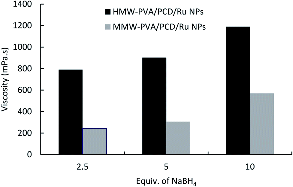 | ||
| Fig. 3 The effect of NaBH4vs. Ru salt ratio on the viscosity of the nanosuspensions prepared from MMW-PVA and from HMW-PVA (8%wt/vol) with 124 mg of PCD and 4.04 mg of Ru(NO)(NO3)3. | ||
Electrospinning PVA/PCD/Ru NP systems
Then, nanosuspensions based on MMW-PVA and HMW-PVA (fixed at 8% wt/vol)/PCD/Ru were electrospun. The fixed electrospinning parameters were solution flow rate, 0.2 mL h−1; voltage, 20 kV; and tip-to-collector distance, 25 cm. The variable parameters of the solution were NaBH4 concentration (ranging from 0 to 10 equivalents vs. Ru salt) and PVA molecular weight. PCD and Ru salt amounts were kept constant in all nanosuspensions. No bead formation was observed. Fig. 4 shows the scanning electron microscopy (SEM) images of NFs based on PVA alone and on PVA/PCD/Ru NPs, collected on aluminum foil. Considering all of the size distributions in Fig. 4, it could be concluded that the mean diameter of the NFs increases with the amount of NaBH4 in addition to the molecular weight of PVA. Indeed, for NFs made from MMW-PVA, the mean diameter of the NFs is 140 ± 31 nm, 159 ± 26 nm, 239 ± 28 nm and 503 ± 55 nm for, respectively, 0 eq., 2.5 eq., 5. eq. and 10 eq. of NaBH4 with respect to Ru molar quantity. Furthermore, at a constant amount of NaBH4, the mean diameter of NFs moves from 140 ± 31 nm to 271 ± 23 nm for PVA-MMW and PVA-HMW NFs and the same tendency is observed with the other hybrid materials. For instance, the mean diameter of NFs moves from 159 ± 26 nm to 353 ± 40 nm for NFs synthesized with 2.5 eq. of NaBH4, respectively, for MMW-PVA/PCD/Ru NFs and HMW-PVA/PCD/Ru NFs, from 239 ± 28 nm to 507 ± 123 nm for NFs synthesized with 5 eq. of NaBH4 for MMW-PVA/PCD/Ru NFs and HMW-PVA/PCD/Ru NFs, respectively. It is noteworthy that the nanosuspension based on HMW-PVA and 10 equivalents of NaBH4 was not electrospinnable, due to its too high viscosity. Overall, these results displayed that NF diameters were correlated with nanosuspension viscosities which depend on NaBH4 ratio and PVA molecular weight.34 | ||
| Fig. 4 SEM images of nanofibers based on MMW-PVA and on HMW-PVA and the diameter distribution of as prepared nanofibers (without thermal post-treatment), nanofibers electrospun from pure PVA solutions (A and E) and from nanosuspensions prepared with 114 mg PCD + 40 μmol Ru ([PCD/Ru NPs]) and upon addition of 2.5 (B and F), 5 (C and G) and 10 (D) molar equivalents of NaBH4versus Ru(III). | ||
To investigate the influence of the amount of PCD/Ru NPs in the nanosuspensions on the nanofiber morphology, two NF samples were prepared from colloidal suspensions containing twofold and fourfold PCD/Ru NP concentrations, i.e. 228 mg PCD/80 μmol Ru and 456 mg PCD/160 μmol Ru (2[PCD/Ru NPs] (named 2[Ru]0) and 4[PCD/Ru NPs] (named 4[Ru]0), respectively, in Fig. 5) keeping the amount of NaBH4 constant (15.2 mg). The resulting NFs retained the same mean diameter when multiplying the concentration of PCD/Ru NPs by two, the mean diameter of the NFs moved from 503 ± 55 nm to 487 ± 77 nm, but the mean diameter of the NFs increased noticeably up to 783 ± 281 nm when the concentration of PCD/Ru NPs was multiplied by four in the nanosuspension.
 | ||
| Fig. 5 SEM images and size distribution of nanofibers based on MMW-PVA prepared with 2[PCD/Ru NPs] (A and B) and 4[PCD/Ru NPs] (C and D). 10 equivalents (15.2 mg) of NaBH4 were used in the preliminary reduction step. | ||
In order to have a better characterization of Ru NPs incorporated in the NFs, a closer study by transmission electron microscopy (TEM) on the composite NFs of PVA/PCD/Ru NPs was realized (Fig. 6).
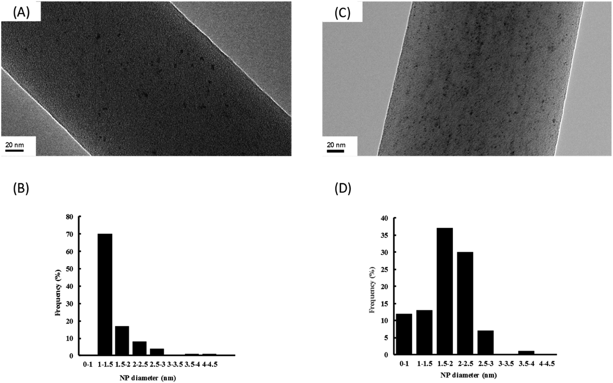 | ||
| Fig. 6 TEM images at a magnification of ×80000 and the size distribution of Ru NPs observed on MMW-PVA nanofibers prepared from nanosuspensions of standard compositions [PCD/Ru NPs] (A and B) and 4[PCD/Ru NPs] (C and D). 10 equivalents (15.2 mg) of NaBH4 were used in the preliminary reduction step. | ||
It should be noticed that whatever the concentration of Ru incorporated into the NFs, Ru NPs are always homogeneously dispersed onto the surface of the NFs without any aggregates. Moreover, the so-obtained Ru NPs are very small with a mean diameter about 1–1.5 nm and 1.5–2 nm, respectively, for composite NFs with Ru concentrations of [Ru]0 and 4[Ru]0. It means that the size of the Ru NPs remains small after the electrospinning step in comparison to our previous work where we focused on the characterization of Ru NPs stabilized by PCD in aqueous media without PVA.24
The dispersion of the Ru NPs onto and into these composite NFs was also studied by HAADF-STEM (Fig. 7).
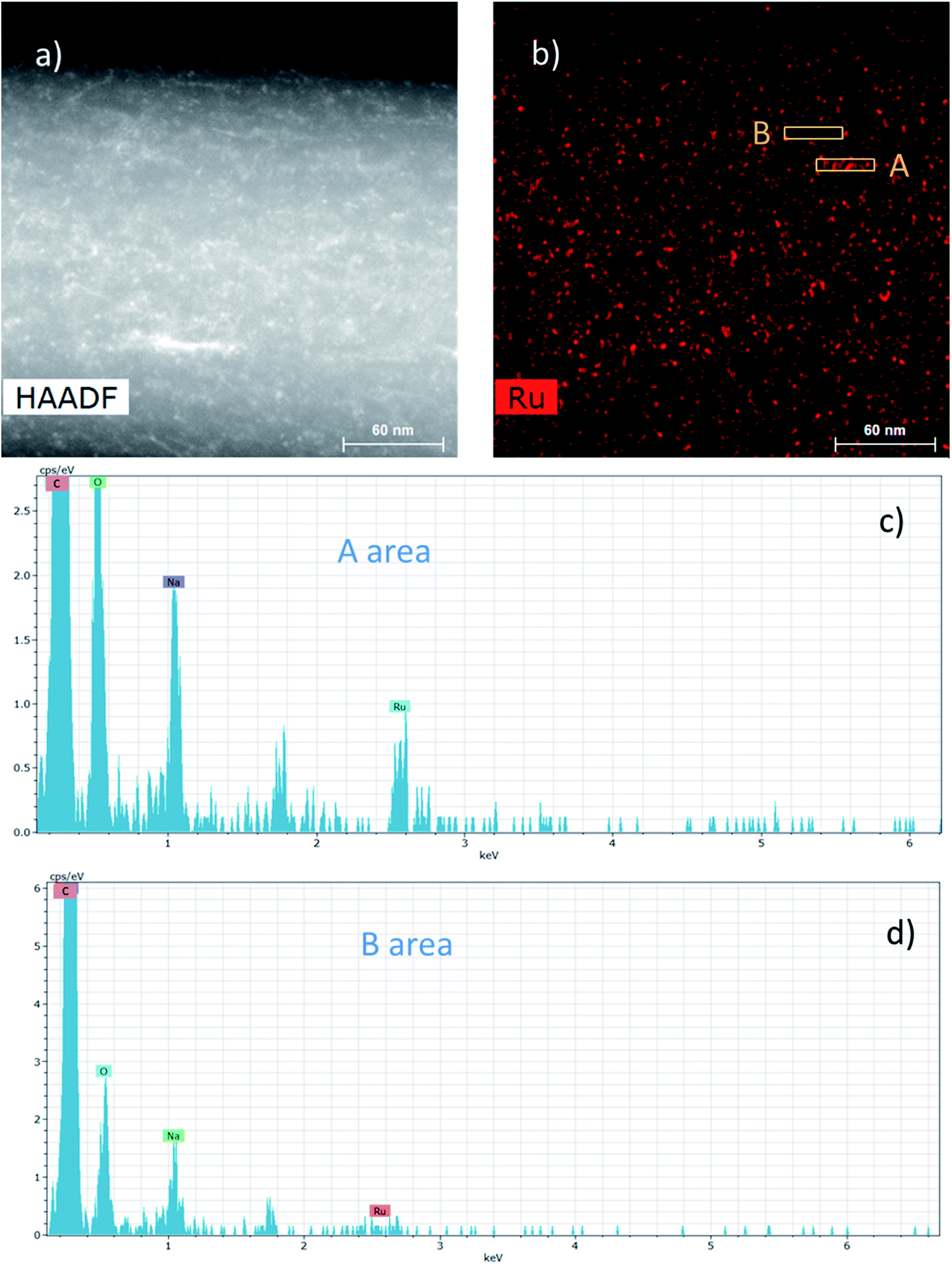 | ||
| Fig. 7 (a) HAADF-STEM image of a catalytic NF prepared from a nanosuspension prepared with 4[PCD/Ru NPs], 10 equivalents of NaBH4 and MMW-PVA. (b) EDS mapping corresponding to the Ru element. (c and d) EDS spectra of areas A and B. | ||
The HAADF-STEM image of a NF presented in Fig. 7a could highlight the presence of nanoparticles in the range of 2–3 nm. Besides, EDS mapping considering the Ru element in Fig. 7b displays more specifically the presence of Ru NPs and it clearly shows that the Ru NPs are homogeneously distributed into and onto the NFs. Fig. 7c and d display the EDS spectra from two different areas A and B of the Ru mapping, respectively, rich and poor in Ru NPs. The Ru signal at 2.55–2.6 keV is clearly visible in Fig. 7c in contrast to Fig. 7d. Whatever the analyzed area, the C and O signals coming from the PVA matrix and also the Na signal coming from the sodium borohydride used as a reducing agent can also be observed.
Stabilization of NFs by heat treatment
As the glass transition (Tg) of PVA usually appears around 85 °C, the dimensional and morphological damage of the nanowebs could be expected in a catalytic process developed in the gas phase, where the temperature range can be 100–150 °C. Wijanarko et al. and Miraftab et al. showed that such a risk could be ruled out by applying a thermal post-treatment of PVA NFs in the 110–180 °C temperature range that involved NF stabilization, increasing their crystallinity due to physical crosslinking, and resulting in the PVA NF insolubility, even in boiling water.35,36 Therefore, nanofibrous samples of PVA/PCD/Ru NPs based on MMW PVA were heated after their electrospinning at 130, 160 and 190 °C for 2 hours. It was observed that the heat treatment made the NFs stiffer and more fragile and also provoked the yellowing of the NF samples. Fig. 8 shows the SEM images of heat treated MMW-PVA and MMW-PVA/PCD/Ru based nanofibers, resulting from the electrospinning of solutions containing or not containing NaBH4. Regardless of the application or not of the thermal post-treatment (TT), the increase in fiber diameters was observed when NaBH4 was present in the solution. Besides, while no significant variation of NFs in the nanowebs was detected after thermal treatments at 130 and 150 °C, after heat treatment at 190 °C, stabilization of the morphology of NFs is clearly observed when NaBH4 was present in the precursor electrospun aqueous mixtures. Both phenomena described here indicate that the presence of NaBH4 influences not only the fiber diameter, but also their thermal stability. In fact, as explained above, NaBH4 used in the electrospun solutions is transformed into NaBO2 not only upon reaction with water, but also through the oxydo–reduction reaction with the Ru(III) salt. Therefore, our results confirm that NaBO2 resulting from the oxidation of NaBH4 acts as a physical crosslinking agent of PVA through hydrogen bonding. Such interactions between NaBO2 and PVA were observed in the solution through the viscosity increase shown in Fig. 3. As displayed in Fig. 8, the consequence is that the diameters of the NFs increased from 140 ± 31 nm up to 330 ± 104 nm, and from 348 ± 48 nm up to 454 ± 41 nm when NaBH4 was added in the electrospun solutions. Besides, hydrogen bonding between NaBO2 and PVA can also explain the increase of the stability of the NFs at elevated temperatures. Interestingly, Fig. 8 also shows that whatever their composition, the NF diameters increased systematically after heating at 130, 160 and 190 °C. This can be attributed to PVA chain relaxation upon heating, leading to NF contraction, and subsequently to the sample shrinking phenomenon observed at the macroscopic scale. So, PVA chain rearrangements induced by heat treatment can be supposed to provoke such a NF diameter increase upon heating.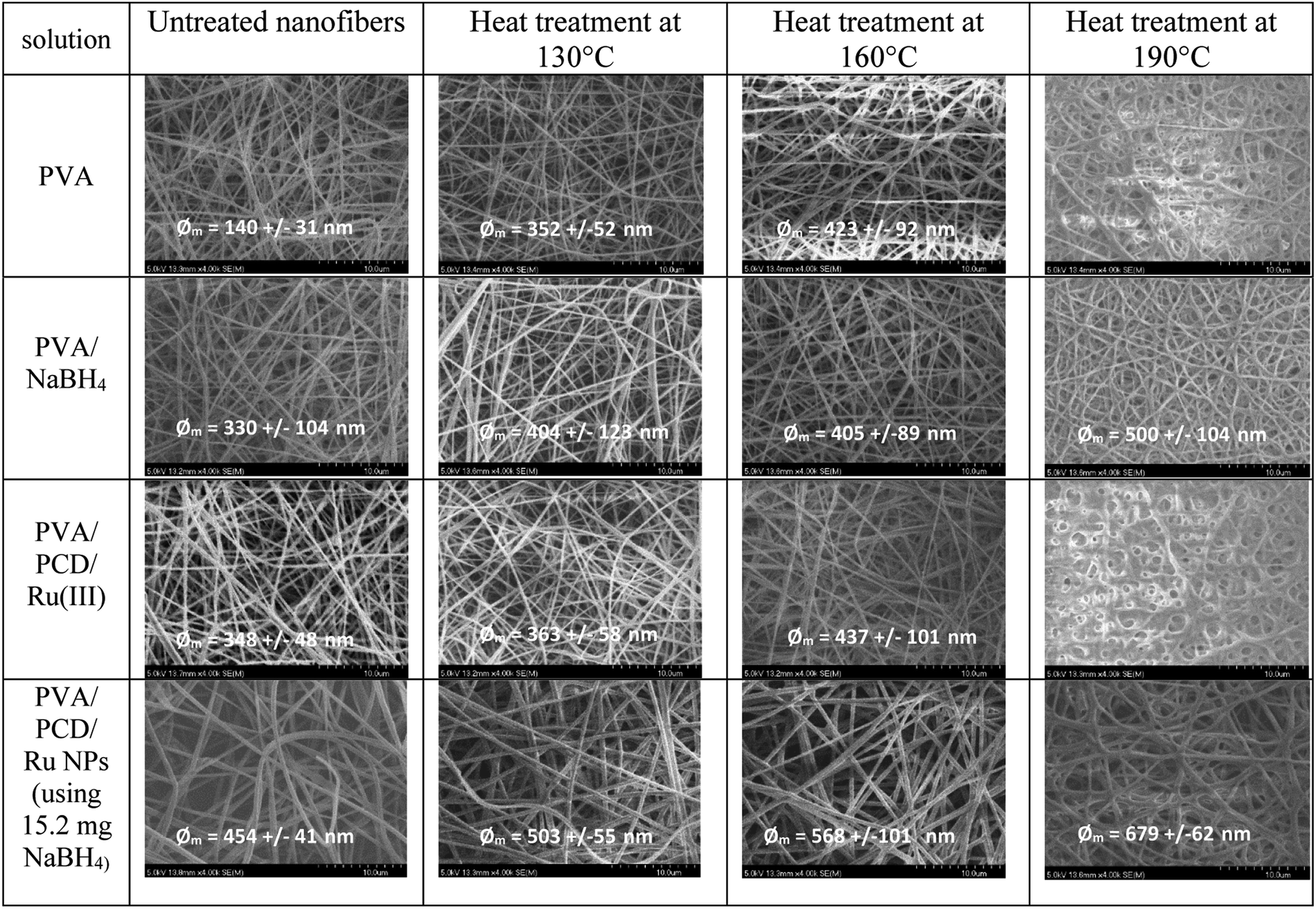 | ||
| Fig. 8 SEM images of nanofibers based on MMW-PVA prepared from different solutions containing and not containing Ru salts, in the presence and absence of NaBH4 collected after electrospinning and after thermal treatment at 130, 160 or 190 °C (magnification ×4000). | ||
DSC analyses
DSC curves of PVA and PVA-PCD/Ru NPs before and after TT at 160 °C were recorded between −80 °C and 210 °C. Fig. 9 shows that all samples present first order endothermic glass transition in the 45–50 °C temperature range, overlapped by chain relaxation signals. Interestingly, these phenomena were remarkably reduced after TT of PVA and PVA-PCD/Ru samples, indicating that TT provoked a change in the PVA chain conformation in the NFs.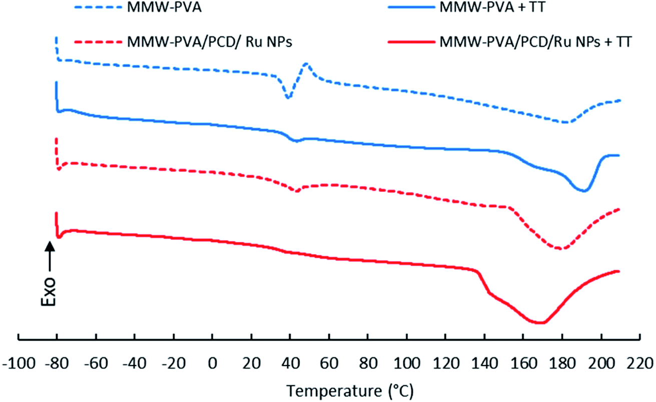 | ||
| Fig. 9 DSC curves of nanofibers before and after thermal post-treatment (TT) at 160 °C, based on MMW-PVA (A); MMW-PVA + TT (B); MMW-PVA/PCD/Ru NPs (C) and MMW-PVA/PCD/Ru NPs + TT (D). | ||
Then, endothermic broad melting peaks appear from 140 °C to 200 °C, centered between 170 and 190 °C. A peak shoulder clearly appeared after TT of NFs. This indicated that a new crystalline phase was formed upon TT. As observed in Table 2, the corrected melting enthalpy measured for PVA NFs slightly increased from 59 up to 63 J g−1 after TT. Besides, the presence of PCD/Ru NPs in NFs provoked a sharp increase of melting enthalpy to 121 J g−1 after electrospinning, and up to 176 J g−1 after thermal post-treatment. When comparing the DSC curves of PVA and PVA-PCD/Ru NFs before TT, it appears that PCD/Ru NPs dispersed in the electrospun solution influenced the crystallization of PVA chains during the electrospinning process. To conclude, both the post-thermal treatment at 160 °C and the presence of PCD/Ru NPs provoked an increase of NF crystallinity.
| NF sample | T m (°C), 1st cycle | ΔHm (J g−1); 1st cycle; raw | ΔHm (J g−1); 1st cycle; corrected |
|---|---|---|---|
| (A) MMW-PVA | 181.9 | 59 | 59 |
| (B) MMW-PVA TT | 191.1 | 63 | 63 |
| (C) MMW-PVA + NaBH4 | 184.1 | 68 | 69 |
| (D) MMW-PVA + NaBH4 TT | 186.0 | 39 | 39 |
| (E) MMW-PVA/PCD/Ru NPs | 179.7 | 83 | 121 |
| (F) MMW-PVA/PCD/Ru NPs TT | 168.4 | 121 | 176 |
Catalytic activity
Finally, the catalytic activity of NFs constituted by MMW-PVA/PCD/Ru NPs, with the Ru concentration of 4[PCD/Ru NPs] without any thermal pretreatment (MMW-PVA/PCD/4[Ru]0 NP NFs) and those submitted to a thermal pre-treatment at 180 °C for 8 h (MMW-PVA/PCD/4[Ru]0 NP NFs + TT), was evaluated in the hydrogenation of styrene under 10 bar of H2 and at 30 °C. The [styrene]/[Ru] molar ratio was fixed at 100 with respect to the theoretical Ru amount coming from the starting PCD/Ru colloidal suspension (4[Ru]0). Fig. 10 shows that after 6 hours of reaction time, for MMW-PVA/PCD/4[Ru]0 NP NFs, the conversion of styrene is about 57% and the ethylbenzene/ethylcyclohexane selectivity is about 97/3, and for MMW-PVA/PCD/4[Ru]0 NP NFs + TT, the conversion of styrene is about 36% and the ethylbenzene/ethylcyclohexane selectivity is about 80/20. The decrease of catalytic activity in the case of MMW-PVA/PCD/4[Ru]0 NP NFs + TT could be explained by an increase of the steric hindrance around the Ru NPs due to the reticulation of the PVA NFs after the thermal treatment. Surprisingly, only a few articles have reported the use of ruthenium heterogeneous catalysts for the hydrogenation of styrene. For catalysts prepared without any calcination step, it should be noticed that the team of Polshettiwar has reported in 2015 the use of Ru NPs supported on fibrous nanosilica for the hydrogenation of styrene under 7 bar of hydrogen and a styrene/Ru molar ratio of 192 in toluene at room temperature.37 Finally, 15% of styrene was converted into ethylbenzene within 1 h. It means that our catalytic results are similar to these catalytic results in terms of catalytic activity and selectivity. It should be noticed that, in order to better understand the catalytic process, a kinetic profile of this reaction was obtained for 8 h considering the two previously mentioned catalysts (Fig. 10). | ||
| Fig. 10 Kinetic profile of the catalytic hydrogenation of styrene by (♦) MMW-PVA/PCD/4[Ru]0 NP NFs, (●) MMW-PVA/PCD/4[Ru]0 NP NFs + TT and (▲) MMW-PVA NFs prepared and then immersed in PCD/4[Ru]0 NP nanosuspension. Reaction conditions: [styrene]/[Ru] = 100, 10 bar H2, 30 °C, decane (12 mL), stirring = 750 rpm. Catalytic membranes were withdrawn from the reactor after 6 hours. | ||
As can be seen in Fig. 10, whatever the nature of the catalyst, the conversion evolves linearly. Moreover, after 6 h of reaction time, these catalytic NFs were removed from the reaction medium and the conversion of styrene was stopped in the absence of these hybrid materials. These experiments clearly show that the catalytic activity comes from Ru NPs embedded onto and into the NFs and that no leaching of Ru NPs is observed during the catalytic process. It should be noticed that another heterogeneous catalyst was synthesized from PCD/Ru NPs adsorbed onto MMW-PVA NFs. In this case, PCD/Ru NPs were synthesized thanks to an experimental method described in our previous work24 with a Ru concentration of 4[Ru]0. Then MMW-PVA NFs were dipped in the PCD/Ru colloidal suspension for 24 h. After removal, the MMW-PVA NFs impregnated with PCD/Ru NPs were dried for one week. These catalytic NFs were then used in the hydrogenation of styrene. Interestingly, as observed in Fig. 10, the conversion of styrene carried on after the removal of these catalytic NFs from the reactor after 6 hours of reaction. The conservation of the conversion of styrene in the absence of the catalytic NFs could be due to the leaching of Ru NPs into the organic phase during the catalytic run. This additional experiment clearly highlights a benefit of our strategy, that is the Ru NPs are incorporated in the NF matrix during the electrospinning step. In this case, Ru NPs are strongly embedded in the NFs in contrast to classical heterogeneous NF supported catalysts where noble metal NPs are incorporated on the support after the electrospinning process.
Conclusion
In this paper, composite nanofibers (NFs) were synthesized through a one-pot process by electrospinning, consisting of Ru nanoparticles stabilized by poly(cyclodextrin citrate) that were embedded in a matrix based on poly(vinyl alcohol) (PVA) of different molecular masses. These PVA based NFs were fully characterized by SEM, TEM, and TGA-DSC. SEM analyses clearly showed that the diameter of the NFs depended on the chosen PVA molecular weight, on the amount of added NaBH4 and on the concentration of PCD/Ru NPs in the electrospun solution. When these composite NFs were submitted to a heat post-treatment, SEM analyses displayed that the morphology of the nanowebs loaded with Ru NPs presented enhanced resistance to temperature up to 190 °C compared to pure PVA NFs. This improvement could be attributed to (i) NaBO2 resulting from NaBH4 oxidation and reaction with water, playing the role of a crosslinking agent of the PVA matrix through hydrogen bonding and (ii) the crystallization of PVA chains promoted by Ru NPs as evidenced by DSC. This study clearly showed the beneficial effect of the synthesis method of the colloidal suspension on the resistance of the NFs coming from the chemical reduction of a ruthenium metal precursor by an excess of sodium borohydride. Ru NPs with a size ranging from 1 to 2 nm were observed by TEM and HAADF-STEM, and EDS mapping clearly showed that these Ru NPs were homogeneously embedded in the matrix of NFs. Finally, these composite nanofibers containing Ru NPs have proven to be catalytically active in the hydrogenation of styrene with good selectivity to ethylbenzene. It is the first example of a heterogeneous catalyst made by embedding Ru NPs into NFs by the electrospinning method for the classical hydrogenation reaction under hydrogen. Interestingly, catalytic results displayed that even though they are embedded in the NF matrix, Ru NPs remained accessible to hydrogen and to styrene. In future studies, the role of CD cavities in the catalytic mechanism should be investigated, and the process of elaboration of NF supported catalysts will be extended to other types of substrates such as biosourced substrates or other types of metal NPs.Conflicts of interest
There are no conflicts to declare.Acknowledgements
This project was funded by Région Hauts-de-France (START-AIRR #2017_02231 CATAFAME). The TEM facility in Lille (France) is supported by the Région Hauts-de-France and the European Regional Development Fund (ERDF). Electrospinning equipment was supported by Federation de Recherche Eugene Chevreul (FR2638) in the frame of CPER ARCHI-CM funded by ERDF. The authors are grateful to Dr Ahmed Addad for his contribution in setting up the TEM measurements.References
- S. A. Formals and R. Schreiber-Gastell, Process and Apparatus for Preparing Artificial Threads, US Pat., US1975504A, Anton Formals, 1934 Search PubMed.
- H. Fong, W. D. Liu, C. S. Wang and R. A. Vaia, Polymer, 2002, 43, 775 CrossRef CAS.
- W. E. Teo and S. Ramakrishna, Nanotechnology, 2006, 17(14), 89 CrossRef PubMed.
- A. J. Crosby and J. Y. Lee, Polym. Rev., 2007, 47, 217 CrossRef CAS.
- D. R. Paul and L. M. Robenson, Polymer, 2008, 49, 3187 CrossRef CAS.
- Z. M. Huang, Y. Z. Zhang, M. Kotaki and S. Ramakrishna, Compos. Sci. Technol., 2003, 63(15), 2223 CrossRef CAS.
- J. D. Schiffman and C. L. Schauer, Polym. Rev., 2008, 48, 317 CrossRef CAS.
- M. M. Demir, M. A. Gulgun, Y. Z. Menceloglu, B. Erman, S. S. Abramchuk, E. E. Makhaeva, A. R. Khokhlov, V. G. Matveeva and M. G. Sulman, Macromolecules, 2004, 37, 1787 CrossRef CAS.
- X. F. Lu, Y. Y. Zhao and C. Wang, Adv. Mater., 2005, 17, 2485 CrossRef CAS.
- W. J. Jin, H. K. Lee, E. H. Jeong, W. H. Park and J. H. Youk, Macromol. Rapid Commun., 2005, 26, 1903 CrossRef CAS.
- X. Y. Xu, Q. B. Yang, Y. Z. Wang, H. J. Yu, X. S. Chen and X. B. Jing, Eur. Polym. J., 2006, 42, 2081 CrossRef CAS.
- C. Chen, Y. Tang, B. Vlahovic and F. Yan, Nanoscale Res. Lett., 2017, 12, 451 CrossRef PubMed.
- A. Roucoux, J. Schulz and H. Patin, Chem. Rev., 2002, 102, 3757 CrossRef CAS PubMed.
- D. Li and Y. Xia, Adv. Mater., 2004, 16(14), 1151 CrossRef CAS.
- P. K. Jain, X. Huang, I. H. El-Sayed and M. A. El-Sayed, Acc. Chem. Res., 2008, 41(12), 1578 CrossRef CAS PubMed.
- H. Liang, C. Li, J. Bai, L. Zhang, L. Guo and Y. Huang, Appl. Surf. Sci., 2013, 270, 617 CrossRef CAS.
- C. P. Li, H. J. Duan, J. Bai and T. Xu, Adv. Mater. Res., 2012, 550, 205 Search PubMed.
- C. Saquing, J. Manasco and S. A. Khan, Small, 2009, 5(8), 944 CrossRef CAS PubMed.
- A. Celebioglu, Z. Aytac, O. C. O. Umu, A. Dana, T. Tekinay and T. Uyar, Carbohydr. Polym., 2014, 99, 808 CrossRef CAS PubMed.
- J. Bai, Q. Yang, M. Li, S. Wang, C. Zhang and Y. Li, Mater. Chem. Phys., 2008, 111, 205 CrossRef CAS.
- M. Aref Khalily, M. Yurderi, A. Haider, A. Bulut, B. Patil, M. Zahmakiran and T. Uyar, ACS Appl. Mater. Interfaces, 2018, 10, 26162 CrossRef PubMed.
- F. Topuz and T. Uyar, Nanoscale Adv., 2019, 1, 4082 RSC.
- A. Celebioglu, F. Topuz and T. Uyar, New J. Chem., 2019, 43, 3146 RSC.
- R. Herbois, S. Noel, B. Léger, S. Tilloy, S. Menuel, A. Addad, B. Martel, A. Ponchel and E. Monflier, Green Chem., 2015, 17, 2444 RSC.
- B. Martel, D. Ruffin, M. Weltrowski, Y. Lekchiri and M. Morcellet, J. Appl. Polym. Sci., 2005, 97, 433 CrossRef CAS.
- L. F. Gudeman and N. A. Peppas, J. Appl. Polym. Sci., 1995, 55, 919 CrossRef CAS.
- H. S. Mansur, R. L. Oretice and A. A. Mansur, Polymer, 2004, 45, 7193 CrossRef CAS.
- M. M. Lakouraj, M. Tajbakhsh and M. Monkhtary, Iran. Polym. J., 2005, 14, 1022 CAS.
- S. J. Kim, S. J. Park, T. D. Chung and S. I. Kim, J. Appl. Polym. Sci., 2003, 89, 2041 CrossRef CAS.
- S. J. Kim, S. J. Park and S. I. Kim, React. Funct. Polym., 2003, 55, 53 CrossRef CAS.
- F. Peng, Z. Jiang, C. Hu, Y. Wang, L. Lu and H. Wu, Desalination, 2006, 193, 182 CrossRef CAS.
- D. Ghemati and D. Aliouche, J. Appl. Spectrosc., 2014, 81, 2 CrossRef.
- L. Dai, B. Nadeau, X. An, D. Cheng, Z. Long and Y. Ni, Sci. Rep., 2016, 6, 1 CrossRef PubMed.
- C. Zhang, X. Yuan, L. Wu, Y. Han and J. Sheng, Eur. Polym. J., 2005, 41, 423 CrossRef CAS.
- T. A. W. Wijanarko, A. Kusumaatmaja, R. Chotimah and K. Triyana, AIP Conf. Proc., 2016, 1755, 150010 CrossRef.
- M. Miraftab, A. N. Saifullah and A. Cay, J. Mater. Sci., 2015, 50, 1943 CrossRef CAS.
- M. Dhiman, B. Chalke and V. Polshettiwar, ACS Sustainable Chem. Eng., 2015, 3, 3224 CrossRef CAS.
| This journal is © The Royal Society of Chemistry 2020 |