
Polarized blue photoluminescence of mesoscopically ordered electrospun non-conjugated polyacrylonitrile nanofibers†
Xiaojian
Liao
 a,
Frank-Julian
Kahle
b,
Bin
Liu‡
cd,
Heinz
Bässler
b,
Xinghong
Zhang
c,
Anna
Köhler
*b and
Andreas
Greiner
*a
a,
Frank-Julian
Kahle
b,
Bin
Liu‡
cd,
Heinz
Bässler
b,
Xinghong
Zhang
c,
Anna
Köhler
*b and
Andreas
Greiner
*a
aUniversity of Bayreuth, Macromolecular Chemistry, Bavarian Polymer Institute, Universitätsstrasse 30, 95440 Bayreuth, Germany. E-mail: greiner@uni-bayreuth.de
bUniversity of Bayreuth, Experimental Physics II, Bavarian Polymer Institute and BIMF, Universitätsstrasse 30, 95440 Bayreuth, Germany. E-mail: anna.koehler@uni-bayreuth.de
cMOE Key Laboratory of Macromolecular Synthesis and Functionalization, Department of Polymer Science and Engineering, Zhejiang University, Hangzhou 310027, P. R. China
dSchool of Energy and Power Engineering, North University of China, Taiyuan 030051, China
First published on 2nd April 2020
Abstract
Conjugated polymers and oligomers that emit polarized light are used as active materials in various optoelectronic device applications, notably organic light-emitting diodes (OLEDs). Here, we demonstrate the fabrication of electrospun polarized light-emitting fibers from a non-conjugated polymer that can be aligned by a simple heat-stretching process. Upon excitation at 340 nm, ribbons made from the nanofibers show polarized deep blue luminescence with an anisotropy of 0.37 and a quantum yield of about 31%. Furthermore, they exhibit room temperature green phosphorescence with a lifetime of about 200 ms as well as a delayed deep blue fluorescence resulting from triplet–triplet annihilation (non-coherent photon upconversion) (TTA). Wide and small angle X-ray scattering experiments show that the stretched electrospun fibers are highly aligned with nearly perfect uniaxial orientation within the fabricated ribbons. This results in a mechanically robust and flexible material, with a high specific tensile strength (534 ± 28) MPa cm3 g−1 and toughness (79 ± 7) J g−1. The combination of efficient polarized deep blue luminescence, room temperature phosphorescence, TTA, mechanical robustness and flexibility of these fibers opens up new avenues for applications of non-conjugated polymers.
New conceptsWe show in our contribution submitted to Materials Horizons a concept for the polarized light emission of non-conjugated polymers, here polyacrylonitrile (PAN). This concept is based on the high orientation of electrospun PAN fibers, which allows the molecular orientation of PAN macromolecules and thereby creates polarized emission of PAN. Polarized light emission is very important for a variety of applications, for example sensors and displays. Materials Horizons is the perfect platform for the introduction of this concept. It is important to say that the processing of non-conjugated polymers is far easier than the processing of conjugated polymers, which are the gold standard for light emission. However, the molecular orientation of non-conjugated randomly coiled polymers is rather limited. With their processing by electrospinning, the required high molecular orientation could be achieved. With this, we could now explore the polarized light emission of non-conjugated polymers and thereby open the field for a wide variety of non-conjugated polymers. |
An approach to reduce power consumption in next-generation display materials is to employ compounds that emit polarized light as this allows for the fabrication of high brightness displays with lower power consumption.1 At the same time, the compounds should be solution-processable to allow for low-cost processing methods such as spin-coating, ink-jet printing or roll-to-roll processing. The resulting materials should be mechanically flexible, lightweight and thin, so that they can be used in numerous applications – including foldable display screens and OLEDs.2,3 These applications call for the use of organic compounds such as π-conjugated oligomers or polymers. Obtaining polarized emission from solution-processed compounds can be challenging. Approaches include aligning conjugated polymers, e.g. by applying a sheer force through rubbing with a cloth or using a Teflon roller, by deposition onto nanogrooved substrates with subsequent heating of the film into a liquid crystalline phase followed by rapid quenching, or mechanically aligning fibres by stretching or imprinting a film.4,5 By the combination of these methods, highly polarized blue electroluminescence was achieved yet the approach was not suitable for large scale technical use.6 More recently, aligning electrospun nanofibers has attracted attention as a possible approach.4,5,7 Electrospinning is an efficient technique to produce polymer nanofiber nonwoven and yarn materials by electrostatic charging on one of the electrodes and letting a jet of polymer solution propel towards the counter electrode.8–10 Typically, the conjugated polymer, for example (poly[(9,9-dioctylfluorenyl-2,7-diyl)-co-(1,4-benzo-{2,10-3}c;-thiadiazole)] (F8BT) or poly(9,9-dioctylfluo-reny-2,7-diyl) (PFO)), is mixed with a spinnable polymer such as poly(methyl methacrylate) or poly(ethylene oxide) (PEO).11,12 The 1D luminescent nanofibers that result from electrospinning tend to have a large aspect ratio and high surface area (compared to the corresponding bulk materials and 2D thin films), and they are reported to show enhanced mechanical properties, photoluminescence quantum yields (QYs), radiative rates and anisotropy of photoluminescence (PL).13–15 While the method of electrospinning is suitable for industrial scale-up, the use of conjugated polymers is expensive. Moreover, care needs to be taken in the design of novel polymers to avoid PL quenching upon aggregation, in particular when they are aligned.
A different twist to this may be the use of non-conjugated polymers that show aggregation-induced emission, also referred to as clustering-triggered emission (CTE). Some non-aromatic low-molecular weight organic units have been reported to show emission, and even room temperature phosphorescence, when aggregated, e.g. in a film or dense solution.16–20 While the detailed mechanism is not yet fully understood, it seems that for compounds containing nitrogen or oxygen, e.g. in the form of aliphatic amine, carbonyl moieties, ether or hydroxyl groups, aggregation allows for the interaction of adjacent lone pair (n) electrons and/or π-electrons such that an extended delocalized electron system results.19,20 As a result, the emission of the interacting units is in the visible spectral range, quite in contrast to the non-interacting units for which emission is not observed. Such functional groups are easily incorporated into the backbone of non-conjugated polymers (NCPs) that can be electrospun. NCPs that show luminescence in the solid state caused by aggregation induced emission (AIE) have received increasing attention.16–18 In addition to being emissive, they are easily and cheaply made in comparatively large quantities, and they exhibit high molecular weight, mechanical flexibility, processability, diversified polymer backbones, additional stimuli responsiveness and biocompatibility.21 Some of the reported luminescent NCPs are low-cost commodity polymers like polyethylene terephthalate (PET),22 polyacrylonitrile (PAN)16 and sulfonated polystyrene (PS).23
In order to achieve polarized emission from such NCPs, two criteria need to be fulfilled. First, the NCP needs to have functional groups that show AIE, and second, the NCP needs to be macroscopically aligned.3,24,25 The latter is not trivial due to the commonly disordered packing of coiled, long non-conjugated polymeric chains. While the stretching forces during the process of electrospinning could be sufficient for the orientation of polymer chains along the nanofiber long axis of conjugated polymers,26 this force is not strong enough to efficiently stretch the long coiled NCP chains into a macroscopic alignment. Thus, it is still a challenge to achieve a polarized emitting system with facile processability and good reproducibility based on the emerging luminescent NCPs.
We report here the observation of polarized photoluminescence of mesoscopically ordered electrospun nanofiber ribbons (ENRs) and their fabrication from commercial non-conjugated PAN by electrospinning and high heat stretching above the glass transition temperature (Tg) (Fig. 1). The cyano groups in PAN are known to interact and show AIE with fluorescence as well as room temperature phosphorescence.16 The latter is attributed to admixtures of the n–π* transition derived from the nitrogen atoms in the cyano groups. It has been suggested that the interaction between adjacent cyano groups or carbonyl groups leads to the formation of a π-system with through-space conjugation.16–18 The obtained ENRs are light-weight and show excellent mechanical strength and toughness. At room temperature, PL itself consists of prompt fluorescence, delayed fluorescence by triplet–triplet annihilation and phosphorescence. As a result, we show a very intriguing material with a unique property combination of emission, anisotropy and mechanical properties. The ENRs are stable as free-standing objects, which will facilitate potential applications.
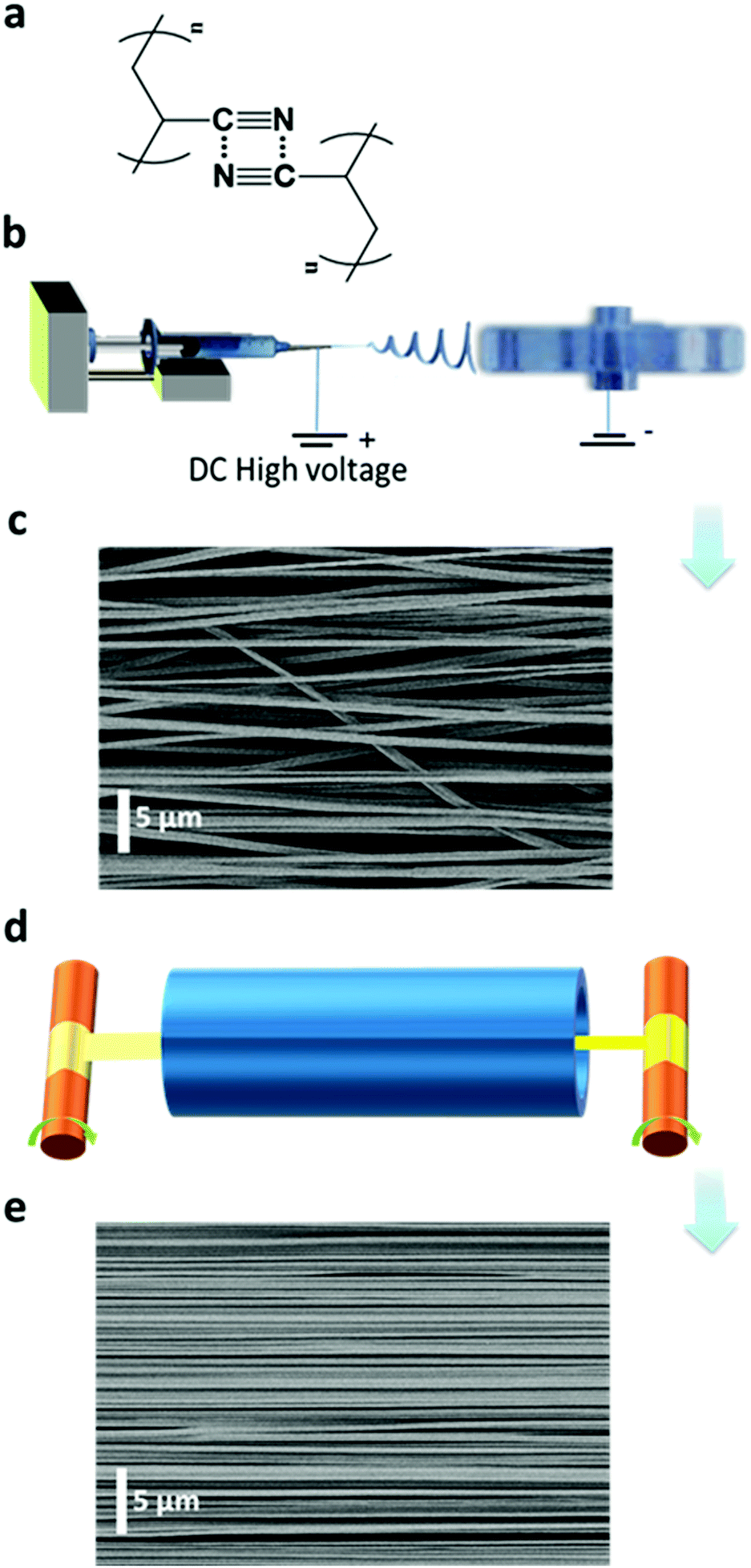 | ||
| Fig. 1 Fabrication process and microstructure of ENRs. (a) Chemical structure of PAN with dipole–dipole attraction interactions. (b) Electrospinning setup. (c) A SEM image of the PAN as-spun ENRs. (d) Roll-to-roll heat-stretching setup. (e) A SEM image of the PAN ENRs after the heat-stretching process with a stretch ratio of six. | ||
PAN is a synthetic, semi-crystalline and non-conjugated polymer (Fig. 1a). A high dipole moment of 3.9 Debye was reported for the substituent cyano group.27,28 This can induce strong attraction or repulsion between adjacent macromolecular chains, which may even result in their orientation.27,28 We were able to obtain highly aligned chains using two sequential steps, as shown in Fig. 1. First, we prepared as-spun ENRs from a pure PAN solution by electrospinning using a conventional collector device with a narrow disc rotating at high speed (1200 rpm) (Fig. 1b). These ENRs had an average width of about 10.0 mm with individual nanofibers having a diameter of (710 ± 160) nm (Fig. S1–S3, ESI†). The nanofibers in the as-spun ENRs have an alignment factor of (92.6 ± 25.7)% (Fig. S2b, ESI†) along the ENR main axis, as assessed by the analysis of scanning electron microscopy (SEM) images (Fig. 1c). Due to the complex deposition path of the jets into nanofibers during electrospinning (Fig. 1b), there are, however, still unavoidable unaligned nanofibers (Fig. 1c, and Fig. S2, ESI†), which could have a negative effect on the anisotropic photophysical properties. Therefore, in a second step, the obtained as-spun ENRs were stretched at 160 °C, i.e. above the Tg of PAN (Tg = 103 °C), along the long axis of the ENRs using a roll-to-roll heat-stretching setup. In this setup, the ENRs were transported through a furnace while being stretched. We observed that stretching at temperatures above the Tg but below the onset of oxidation at 180 °C29 could efficiently and homogeneously extend nanofibers along the axis of the ENRs, as shown in Fig. 1d and Fig. S2b, S3 (ESI†). For this ENR system, the maximum stretching ratio could reach up to six at 160 °C. Through the heat stretching process, as shown in the ESI,† Fig. S1, the width of ENRs decreased down from 10.0 mm to 2.5 mm at a stretching ratio of six. We refer to these stretched ribbons from now on as stretch ratio (SR, stretched length divided by original length) 6 ENRs. Not only the ribbon were reduced in width through the stretching process, the nanofiber diameters were also reduced down to (236 ± 62) nm (SR6 ENRs) (Fig. S2a, ESI†). Concomitantly, a nearly perfect uniaxial orientation of the nanofibers along the axis of the ENRs could be achieved with an alignment factor of (99.97 ± 0.06)% (SR6 ENRs) (Fig. 1e and Fig. S2b, ESI†). This extension is irreversible and remains after the heat-stretching process is completed and the sample has cooled down to room temperature. In contrast, when stretching PAN fibers at temperatures below Tg, the reported extension of the fiber reaches up to 140% (i.e. a SR1.4) and it is almost entirely reversible if the stress is removed. This extension is a response of the PAN fibers to the stress without any changes in the micro-structure.28 However, the high and irreversible extension of PAN nanofibers up to 600% (stretching at 160 °C) suggests that the stretching is accompanied with a re-arrangement of molecular chains in the nanofibers.
The orientation of molecular chains and packing patterns were investigated by using wide-angle/small-angle X-ray scattering (WAXS/SAXS), as shown in Fig. 2 and Fig. S4, S5, Table S1 (ESI†). Upon comparing the WAXS diffractograms of PAN taken from the powder, drop-cast film, and the as-spun ENRs, we observed the same peaks at nearly the same positions: a sharp diffraction peak at 2θ = 16.9° corresponding to the (100) crystal direction and a small diffraction peak at 2θ = 29.4° associated with the (110) crystal direction. The interplanar spacing d corresponding to these two peaks was 5.25 Å and 3.03 Å, respectively. Apart from the crystal peaks, there is a broad feature that arises from the amorphous areas in the samples of the powder, drop-cast film and as-spun ENRs (Fig. 2a). Interestingly, while nearly the same full width at half maximum (FWHM) of 1.35° was observed in the (100) peaks of the powder sample, the film and the as-spun ENRs, this FWHM reduced to nearly half for the heat-stretched SR6 ENRs. This confirms the high quality of the crystallites formed in the SR6 ENRs. In addition, the intensity of the broad feature centred at about 2θ = 25° reduces from the powder and film samples to the as-spun ENR and almost disappears for the SR6 ENRs. A detailed peak analysis (see Fig. S4 and Table S1, ESI†) shows that the crystallinity increases drastically from 51% in the as-spun ribbon to 89% in the heat-stretched SR6 ENRs.
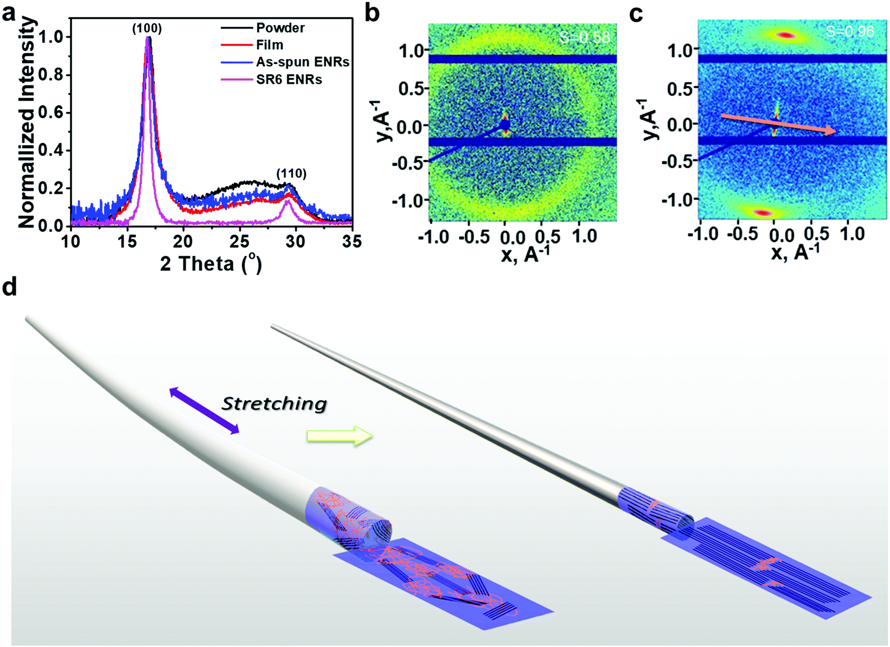 | ||
| Fig. 2 Structural investigation on PAN samples. (a) WAXS spectra of PAN in the form of powder, drop-cast film, as-spun ENRs, and SR6 ENRs. (b) and (c) 2D SAXS scattering pattern images of ENRs before (as-spun ENR) (b) and after stretching (SR6) (c). The arrow in c represent the tensile direction of ENRs. (d) A schematic illustrating the envisaged molecular changes during the heat-stretching process from a semi-crystalline as-spun fiber to an aligned PAN fiber of highly aligned crystalline molecular chains. | ||
Further structural information can be obtained from the 2D SAXS images of the as-spun ENRs and the SR6 ENRs (Fig. 2b and c). For the as-spun samples, we observe a ring, implying a near-isotropic orientation of the crystallites, whereas the SR6 ENRs show two sharp (200)-reflections, implying alignment accompanied by a high orientational order. The calculated orientational order parameters are S = 0.58 for the as-spun ENRs and S = 0.96 for the SR6 ENRs (Fig. 2b and Fig. S5, ESI†). Thus, in summary, the process of heat-stretching leads to the formation of aligned, highly crystalline PAN ENRs. In contrast, in the as-spun ENRs, crystallites have an isotropic orientation, lower crystal quality and the overall fraction of crystalline domains is reduced.
For applications, the mechanical properties of the ribbons can be relevant. The two key parameters of robustness and flexibility can be represented by the specific tensile strength and the toughness, respectively. The ENRs can support higher stresses and show a higher toughness when they are heat-stretched to higher stretching ratios (Fig. S6, ESI†). These results show that high values for specific tensile strength (534 ± 28.0 MPa cm3 g−1) and toughness (79 ± 7 J g−1) of the ENRs are obtained with a stretching ratio of 6 at 160 °C. Evidently, the heat-stretching process and the associated alignment of the crystalline domains are beneficial for obtaining high maximum tensile stress and high toughness.
Furthermore, we found that solid state samples of PAN like powders, films or ENRs showed bright blue emission under irradiation with UV-light (Fig. 3a, and Fig. S7–S9, ESI†), while the acrylonitrile monomer itself did not give any detectable emission above 360 nm (Fig. S10, ESI†). After turning off the excitation, we observed a green afterglow that lasted for several seconds at 77 K. The blue emission as well as the afterglow had already been reported for concentrated solutions of PAN.16 As the emission intensity has been shown to increase with concentration, this effect has been attributed to the effects of clustering of the cyano groups and has been referred to as aggregate induced emission (AIE).16,30
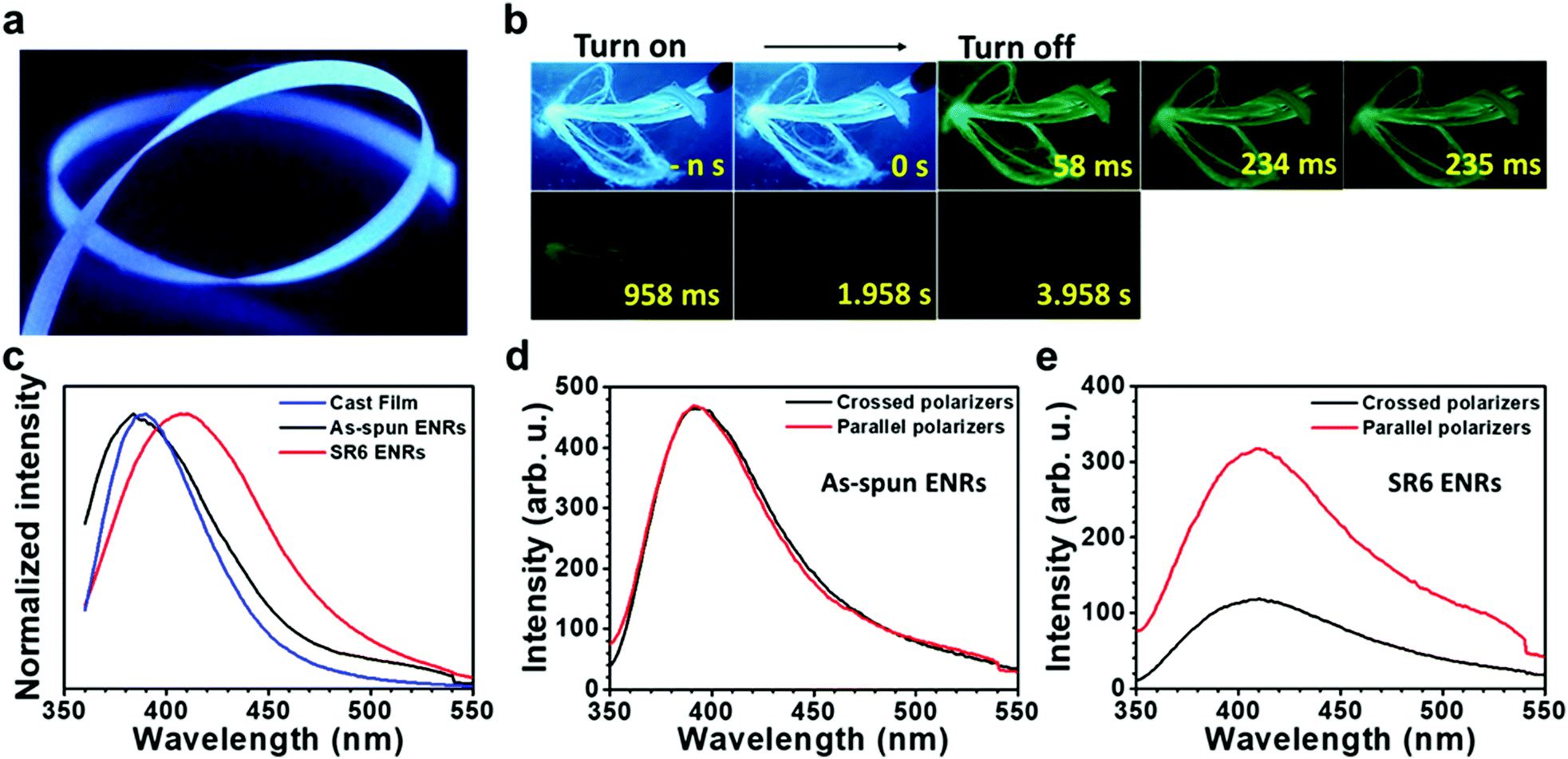 | ||
| Fig. 3 Photoluminescence properties of ENRs. (a) Photograph of SR6 ENRs under UV light irradiation (365 nm). (b) Luminescence photographs of ENRs taken at 77 K under 365 nm UV irradiation and at different times after turning off the UV lamp. (c) Comparison of the PL spectra of the film, as-spun ENRs and SR6 ENRs excited at 340 nm. (d) and (e) Polarization dependent emission spectra of the as-spun ENRs (d) and SR6 ENRs (e) excited at 337 nm. The excitation light was linearly polarized parallel to the long axis of the ENRs. | ||
In order to study the emission properties of the ribbons in more detail and to evaluate the influence of stretching the ribbons on their luminescence properties, we performed a range of additional PL measurements. They were conducted using unpolarized as well as polarized excitation light, detecting in steady state mode as well as in a gated, time-resolved fashion. The steady state (PL) spectra of PAN films and ribbons displayed in Fig. 3c do not show any structure. While the films and the as-spun ENRs feature similar spectra with a maximum at around 394–388 nm, SR6 ENRs feature a red shifted, broadened emission maximum at around 410 nm. The quantum yields of emission are similar for both ribbons and are in the range of 30–32%, thus exceeding the value of 22% that we measured in DMF solution at 80 mg mL−1 (Table S2, ESI†). When excited with light that is linearly polarized parallel to the long axis of the ENRs, the stretched ribbons feature a considerable anisotropy, r = (I‖ − I⊥)/(I‖ + 2I⊥), of 0.37 and a degree of polarization, P = (I‖ − I⊥)/(I‖ + I⊥), of 0.47 for the emission, whereas the as-spun ENRs do not show a dependence of the emission intensity on the position of the analyser (Fig. 3d and e). For the as-spun ENRs, both anisotropy and polarization are basically zero (Table S3, ESI†). This is not the case when exciting with light that is linearly polarized perpendicular to the long axis of the ENR (Fig. S11, ESI†). Evidently, the polarization is induced by the heat-stretching process. Similarly, the increased weight in the red spectral range of the emission of SR6 ENRs as compared to the not stretched films is also associated with the stretching process.
To analyse the emission in more detail, we performed time-resolved measurements, as shown in Fig. 4. In the first 10 ns after the excitation pulse, we observe a broad emission centred at about 425 nm. The lower energy part of this distribution is more intense in the heat-stretched SR6 sample (seen as a higher initial intensity in Fig. 4d), consistent with the redshifted spectrum for continuous wave (CW) excitation (Fig. 3c). Evidently, there is a very wide energetic distribution of emitting states. After a few tens of ns, the emission from the lower-energy part of the distribution has decayed, leaving a significantly narrower spectrum of about half the previous FWHM that peaks around 400 nm. This blue emission decays on a μs to ms timescale and a turquoise emission centred at 450–475 nm remains in the range of ms to s, both from the as-spun ENRs and in the stretch-oriented fibres. When exposing the fibers to oxygen, we find that the long-lived component is strongly reduced by oxygen, in contrast to the shorter lived components (Fig. S12, ESI†). Based on the long lifetime and sensitivity to oxygen, we can attribute the long components at room temperature to delayed fluorescence (centred at 3.1 eV, i.e. 400 nm) and phosphorescence (centred at about 2.7 eV, i.e. 460 nm). Room temperature delayed fluorescence (DF) and phosphorescence are unusual. It has been observed, however, in compounds with significant contributions from n–π* transitions to the emitting state, in particular when the molecule was rigidified, e.g. by aggregation, which suppressed non-radiative decay channels.30 The room temperature spectrum for CW excitation is not affected by oxygen, implying that it results mostly from prompt fluorescence. This is also consistent with the very similar PL QY and the very similar decay dynamics of the as-spun ENRs and SR6 ENRs. If we consider intersystem crossing from the singlet to the triplet state as the dominant non-radiative decay process, and use the 1/e-decay time of 14 ns as a first approximation to the lifetime of the excited singlet states, then the PL QY of 31% implies a radiative decay rate of about 2 × 10⁷ s−1 and an intersystem crossing (ISC) rate of about 5 × 10⁷ s−1. Such high ISC rates are typical for compounds with a significant contribution from n–π* transitions.
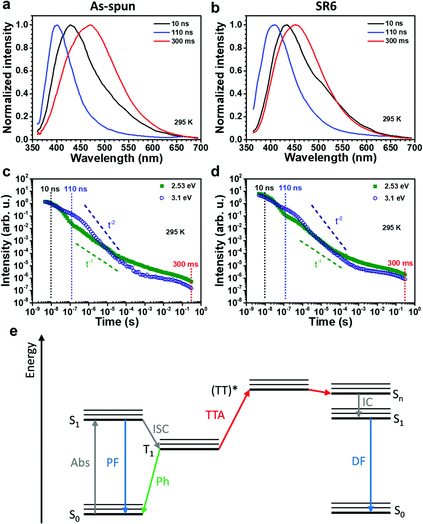 | ||
| Fig. 4 (a and b) Comparison of room temperature PL spectra at different delay times after the excitation of (a) as-spun and (b) stretched SR6 ENRs. (c and d) Temporal PL decay at 295 K of (c) as-spun ENRs and (d) SR6 ENRs evaluated at 2.53 eV and 3.1 eV. Dashed vertical lines indicate the time corresponding to the spectra in (a) and (b). Also indicated are slopes corresponding to t−1 and t−2 for comparison. The gate width was half the delay time. (e) A Jablonski diagram illustrating how TTA can lead to DF. | ||
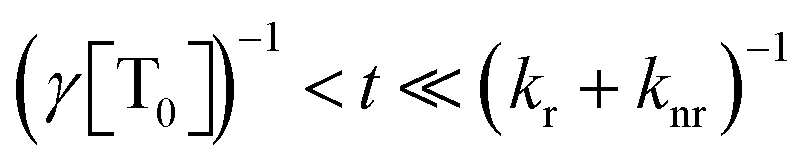
The temporal decay of the long-lived emissions offers a clue for their assignment. Since it is virtually temperature-independent (see Fig. S13 in the ESI†), thermally activated delayed fluorescence can be discarded as the possible origin for the delayed blue component of the spectrum. Instead, it has to be identified as delayed fluorescence caused by the recombination of either geminately bound electron–hole pairs or by triplet–triplet annihilation (TTA).31,32 The latter would be complementary to the work of Wohnhaas et al. who studied dye-sensitized TTA in electrospun poly(methyl methacrylate) fibres.33 Conventional kinetics predicts that the decay of triplets generated via ISC from the singlet state is governed by the interplay between monomolecular decay, described by the radiative (kr) and non-radiative (knr) rate constants, and bimolecular annihilation governed by the bimolecular rate constant γ, i.e.34
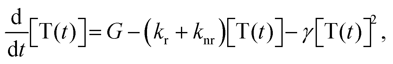 | (1) |
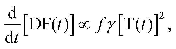 | (2) |
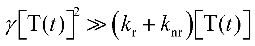 . By solving the rate eqn (1), one obtains the temporal decay of the reservoir of triplet excitations and, therefore, the temporal decay of the phosphorescence.
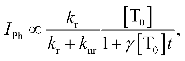 | (3) |
 , the phosphorescence should decay in a power law fashion, i.e. Iph ∝ t−1. Ultimately, the phosphorescence is limited by the intrinsic triplet lifetime. Combining eqn (2) and (3) predicts that in the intermediate time regime, the DF should decay as t−2. From the fact that in the intermediate time regime, the blue component closely follows a t−2 decay over four orders of magnitude while in the same time regime, the phosphorescence decays as t−1, we conclude that the DF is caused by TTA. In passing, we note that the fact that the emission right after the decay of the prompt fluorescence is not time independent (as it should be, according to eqn (3)) is a common signature of dispersive triplet transport.
It is noteworthy that the stretched PAN-fibres show polarized emission also for the phosphorescence part of the spectrum, while the monomer acrylonitrile does not show any phosphorescence.
Summarizing the results of PL spectroscopy, we observe a delayed blue fluorescence as well as green phosphorescence at room temperature in addition to the prompt fluorescence. The DF results from TTA, also referred to as triplet upconversion (UC). The observation of TTA implies that triplet excitons are remarkably mobile in these non-conjugated materials. This opens up a new perspective for electrospun fibers. Non-coherent triplet UC is frequently sought after for biomedical applications and usually requires the use of a sensitizer in addition to the emitter. In electrospun nanofibers, TTA–UC has so far only been achieved when sensitizers and emitters were included in a colloidal nanocapsule inside the electrospun fiber.33,35
In our ENRs, the CW emission is efficient with a quantum yield of about 31% that is similar in the as-spun and stretched samples. However, the stretched samples show highly polarized emission with an anisotropy of 0.37. The lack of polarization in the as-spun sample, and the high degree of orientational order found in SR6 ENRs after the heat-stretching are in excellent agreement, respectively, with the isotropic orientation found for the crystallites by 2D SAXS in the as-spun samples and the high orientation observed in SR6 ENRs after stretching.
Conclusions
We present a concise and efficient fabrication approach to achieve polarized emission from PAN ENRs by mesoscopic ordering. The ribbons are lightweight and have a high strength and toughness. From our analysis, we are able to identify three important molecular design rules to achieve polarized emission in non-conjugated polymers: (i) electrospinning the non-conjugated polymer into nanofibers, (ii) aligned crystal arrangement by sufficient heat-stretching at high temperatures above Tg, and (iii) using functional groups that show AIE when interactions between adjacent groups lead to the formation of a more extended π-system.PAN ENRs satisfy these design requirements by forming a highly ordered macroscopically aligned structure upon stretching at temperatures above Tg. Interactions between adjacent cyano side groups result in the formation of an extended π-system and the occurrence of aggregate induced polarized deep blue emission. They exhibit a photoluminescence quantum yield of 30–32%, which is remarkable for a simple non-conjugated polymer (not particularly designed for light emission). Due to the contribution of n–π* transitions resulting from the nitrogen atoms in the cyano groups, intersystem crossing occurs that leads to the formation of highly mobile triplet states with a quantum energy of about 2.5 eV and a lifetime up to 200 ms at room temperature (1 s at 77 K). These triplets give rise to delayed fluorescence via TTA and to phosphorescence.
Conflicts of interest
There are no conflicts to declare.Acknowledgements
The authors thank Michael Mader for measurements of confocal microscopy, Martin Dulle and Prof. Stephan Förster for the 2D WAXS measurements, and Prof. Paul Smith for the valuable discussion and suggestion. We gratefully acknowledge the financial support of SFB 840, project B8.Notes and references
- L. Wan, J. Wade, F. Salerno, O. Arteaga, B. Laidlaw, X. Wang, T. Penfold, M. J. Fuchter and A. J. Campbell, ACS Nano, 2019, 13, 8099–8105 CrossRef CAS PubMed.
- X. Ai, E. W. Evans, S. Dong, A. J. Gillett, H. Guo, Y. Chen, T. J. Hele, R. H. Friend and F. Li, Nature, 2018, 563, 536–540 CrossRef CAS PubMed.
- B. G. Kim, E. J. Jeong, J. W. Chung, S. Seo, B. Koo and J. Kim, Nat. Mater., 2013, 12, 659–664 CrossRef CAS PubMed.
- K. Chung, Y. Yu, M. S. Kwon, J. Swets, J. Kim and J. H. Youk, MRS Commun., 2015, 5, 169–189 CrossRef CAS.
- K. Chung, D. S. Yang, W.-H. Sul, B.-G. Kim, J. Kim, G. Jang, M. S. Kwon, M. Barłóg, T. S. Lee, S.-Y. Park, M. Al-Hashimi and J. Kim, Macromolecules, 2019, 52, 6485–6494 CrossRef CAS.
- K. S. Whitehead, M. Grell, D. D. C. Bradley, M. Jandke and P. Strohriegl, Appl. Phys. Lett., 2000, 76, 2946–2948 CrossRef CAS.
- K. Yin, L. Zhang, C. Lai, L. Zhong, S. Smith, H. Fong and Z. Zhu, J. Mater. Chem., 2011, 21, 444–448 RSC.
- S. Agarwal, A. Greiner and J. H. Wendorff, Prog. Polym. Sci., 2013, 38, 963–991 CrossRef CAS.
- Y. Ding, H. Hou, Y. Zhao, Z. Zhu and H. Fong, Prog. Polym. Sci., 2016, 61, 67–103 CrossRef CAS.
- X. Liao, M. Dulle, J. Martins, R. B. Wehrspohn, S. Agarwal, S. Förster, H. Hou, P. Smith and A. Greiner, Science, 2019, 366, 1376–1379 CrossRef CAS PubMed.
- S. Pagliara, M. S. Vitiello, A. Camposeo, A. Polini, R. Cingolani, G. Scamarcio and D. Pisignano, J. Phys. Chem. C, 2011, 115, 20399–20405 CrossRef CAS.
- C. C. Kuo, C. T. Wang and W. C. Chen, Macromol. Mater. Eng., 2008, 293, 999–1008 CrossRef CAS.
- A. Macagnano, E. Zampetti and E. Kny, Electrospinning for high performance sensors, Berlin, Germany, Springer, 2015 Search PubMed.
- A. Camposeo, L. Persano and D. Pisignano, Macromol. Mater. Eng., 2013, 298, 487–503 CrossRef CAS.
- W. Han, F. Cui, Y. Si, X. Mao, B. Ding and H. Kim, Small, 2018, 14, 1801963 CrossRef PubMed.
- Q. Zhou, B. Cao, C. Zhu, S. Xu, Y. Gong, W. Z. Yuan and Y. Zhang, Small, 2016, 12, 6586–6592 CrossRef CAS PubMed.
- L. Song, T. Zhu, L. Yuan, J. Zhou, Y. Zhang, Z. Wang and C. Tang, Nat. Commun., 2019, 10, 1315 CrossRef PubMed.
- Q. Li, Y. Tang, W. Hu and Z. Li, Small, 2018, 14, e1801560 CrossRef PubMed.
- Q. Zhou, T. Yang, Z. Zhong, F. Kausar, Z. Wang, Y. Zhang and W. Yuan, Chem. Sci., 2020, 11, 2926 RSC.
- Y. Wang, X. Bin, X. Chen, S. Zheng, Y. Zhang and W. Yuan, Macromol. Rapid Commun., 2018, 39, 1800528 CrossRef PubMed.
- T. L. Mako, J. M. Racicot and M. Levine, Chem. Rev., 2019, 119, 322–477 CrossRef CAS PubMed.
- X. Chen, Z. He, F. Kausar, G. Chen, Y. Zhang and W. Z. Yuan, Macromolecules, 2018, 51, 9035–9042 CrossRef CAS.
- T. Ogoshi, H. Tsuchida, T. Kakuta, T.-a. Yamagishi, A. Taema, T. Ono, M. Sugimoto and M. Mizuno, Adv. Funct. Mater., 2018, 28, 1707369 CrossRef.
- X. Ma, C. Xu, J. Wang and H. Tian, Angew. Chem., Int. Ed., 2018, 57, 10854–10858 CrossRef CAS PubMed.
- J. Yang, X. Zhen, B. Wang, X. Gao, Z. Ren, J. Wang, Y. Xie, J. Li, Q. Peng and K. Pu, Nat. Commun., 2018, 9, 840 CrossRef PubMed.
- R. Dersch, T. Liu, A. Schaper, A. Greiner and J. Wendorff, J. Polym. Sci., Part A: Polym. Chem., 2003, 41, 545–553 CrossRef CAS.
- D. R. Lide, CRC handbook of chemistry and physics: a ready-reference book of chemical and physical data, CRC Press, 1995 Search PubMed.
- G. Henrici-Olivé and S. Olivé, Chemistry, Springer, 1979, pp. 123–152 Search PubMed.
- N. Yusof and A. F. Ismail, J. Anal. Appl. Pyrolysis, 2012, 93, 1–13 CrossRef CAS.
- Z. An, C. Zheng, Y. Tao, R. Chen, H. Shi, T. Chen, Z. Wang, H. Li, R. Deng, X. Liu and W. Huang, Nat. Mater., 2015, 14, 685–690 CrossRef CAS PubMed.
- K. Hong and J. Noolandi, J. Chem. Phys., 1978, 68, 5163–5171 CrossRef CAS.
- Y. V. Romanovskii, V. Arkhipov and H. Bässler, Phys. Rev. B: Condens. Matter Mater. Phys., 2001, 64, 033104 CrossRef.
- C. Wohnhaas, K. Friedemann, D. Busko, K. Landfester, S. Baluschev, D. Crespy and A. Turshatov, ACS Macro Lett., 2013, 2, 446–450 CrossRef CAS.
- A. Köhler and H. Bässler, Electronic processes in organic semiconductors: An introduction, John Wiley & Sons, 2015 Search PubMed.
- S. Baluschev, K. Katta, Y. Avlasevich and K. Landfester, Mater. Horiz., 2016, 3, 478–486 RSC.
Footnotes |
| † Electronic supplementary information (ESI) available. See DOI: 10.1039/d0mh00002g |
| ‡ Present address: School of Energy and Power Engineering, North University of China, Xueyuan Road No. 3 Taiyuan, 030051, China. |
| This journal is © The Royal Society of Chemistry 2020 |