
 Open Access Article
 This Open Access Article is licensed under a
 Creative Commons Attribution 3.0 Unported Licence
Understanding and designing one-dimensional assemblies of ligand-protected metal nanoclusters†
Sakiat
Hossain
 a,
Yukari
Imai
a,
Yuichi
Motohashi
bc,
Zhaoheng
Chen
a,
Daiki
Suzuki
a,
Taiyo
Suzuki
a,
Yuki
Kataoka
a,
Momoko
Hirata
a,
Tasuku
Ono
a,
Wataru
Kurashige
a,
Tokuhisa
Kawawaki
ad,
Takahiro
Yamamoto
cd and
Yuichi
Negishi
*ad
a,
Yukari
Imai
a,
Yuichi
Motohashi
bc,
Zhaoheng
Chen
a,
Daiki
Suzuki
a,
Taiyo
Suzuki
a,
Yuki
Kataoka
a,
Momoko
Hirata
a,
Tasuku
Ono
a,
Wataru
Kurashige
a,
Tokuhisa
Kawawaki
ad,
Takahiro
Yamamoto
cd and
Yuichi
Negishi
*ad
aDepartment of Applied Chemistry, Faculty of Science, Tokyo University of Science, Kagurazaka, Shinjuku-ku, Tokyo 162-8601, Japan. E-mail: negishi@rs.kagu.tus.ac.jp
bRicoh Company, Ltd., Izumi-ku, Ebina, Kanagawa 243-0460, Japan
cDepartment of Liberal Arts, Faculty of Engineering, Tokyo University of Science, Katsushika-ku, Tokyo 125-8585, Japan
dResearch Institute for Science & Technology, Tokyo University of Science, Shinjuku-ku, Tokyo 162-8601, Japan
First published on 23rd December 2019
Abstract
If we wish to use metal clusters as magnetic materials and dipole materials, it is necessary to assemble the clusters to attain a certain material size. However, the types of building-block clusters suitable for assembly are currently very limited, and thereby we have little information on the factors required to assemble metal clusters and the physical properties and functions of such assembled structures. In this research, we found the following four points about thiolate (SR)-protected gold–platinum alloy (Au4Pt2) clusters ([Au4Pt2(SR)8]0); (1) [Au4Pt2(SR)8]0 is a metal cluster that can be used as a building block to form one-dimensional (1D) connected structures (1D-CS) via inter-cluster Au–Au bonds (aurophilic bond); (2) although all [Au4Pt2(SR)8]0 clusters have similar structures, the intra-cluster ligand interactions vary depending on the ligand structure. As a result, the distribution of the ligands in [Au4Pt2(SR)8]0 changes depending on the ligand structure; (3) the differences in the distributions of the ligands influence the inter-cluster ligand interactions, which in turn affects the formation of 1D-CS and changes the connected structure; and (4) the formation of 1D-CS decreases the band gap of the clusters. These results demonstrate that we need to design intra-cluster ligand interactions to produce 1D-CS with desired connecting structures.
New conceptsWe demonstrate that it is necessary to control the intra-cluster ligand interactions in the formation of the 1D-connected structures composed of ligand-protected metal clusters, which is important for their application in devices and to obtain new physical properties and functions. Previous studies have revealed that control of the ligand interactions between adjacent clusters (inter-cluster ligand interactions) is important in the assembly of ligand-protected metal clusters. However, these interactions are supposed to depend on the distribution of the ligands within the individual clusters. In this study, we experimentally corroborated this point and established the concept that it is necessary to control intra-cluster ligand interactions to obtain an assembled structure with the desired connecting structures. The knowledge gained in this study will aid future studies on building-block clusters because it illustrated the importance of considering intra-cluster ligand interactions when designing ligand structure. We anticipate that this concept will dramatically increase our ability to control the assembled structures of ligand-protected metal clusters and thereby the access to materials that take advantage of their properties. |
Introduction
Small metal clusters exhibit physical/chemical properties and functions that are different from those of the corresponding bulk metal. Furthermore, the physical/chemical properties and functions of clusters vary depending on the number of constituent atoms and chemical composition. Metal clusters with these characteristic features have attracted much attention as structural units of functional nanomaterials in a wide range of fundamental and application studies.In recent years, it has become possible to synthesize metal clusters composed of elements such as gold (Au), silver (Ag), platinum (Pt), palladium (Pd) and alloy clusters containing mixtures of these metal elements with atomic accuracy using thiolates (SR),1–19 selenolates,20,21 alkynyl,22 phosphines,23,24 and carbon monoxide25,26 as ligands. These metal clusters have also been extensively studied for applications in chemical sensors,27 photosensitization,28 catalyst,29–31 and solar cells.32,33 In these applications, the metal clusters are dispersed in a solution or supported on a substrate. Because the properties of those clusters are not controlled by the arrangement, there is no particular need to control the arrangement of the clusters in these cases (Scheme 1A and B).
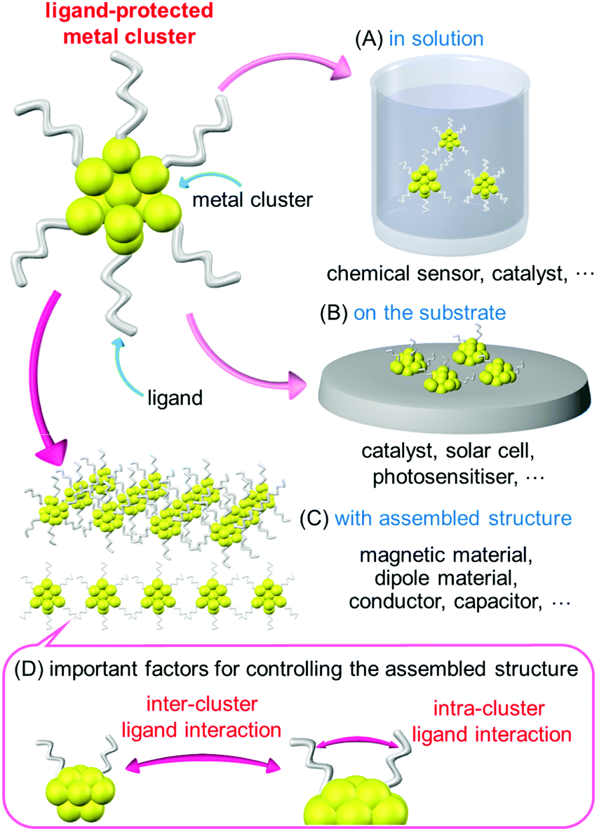 | ||
| Scheme 1 Relation between the states of ligand-protected metal cluster and their possible applications. Metal cluster (A) in solution, (B) on a substrate, and (C) assembled into an organized structure. (D) Important factors for controlling the assembled structure. | ||
These metal clusters are also attractive for use as elements that utilize their magnetic properties34 and electrical conductivity in device.35 However, under existing circumstances, these types of elements are composed of materials with sizes several orders of magnitude larger than that of metal clusters. Therefore, it is necessary to assemble metal clusters to obtain materials of a certain size for use in these types of elements (Scheme 1C). To date, several studies have been published on the assembly of ligand-protected metal clusters. For example, Jiang et al.36 performed density functional theory (DFT) calculations on one-dimensional (1D) connected structures (1D-CS) in which Au13 clusters were linked via a single Au atom. They theoretically predicted that such 1D-CS would exhibit different properties depending on the charge state of the metal clusters (metal or semiconductor). Maran and co-workers fabricated 1D-CS in which SR-protected Au25 clusters ([Au25(SR)18]0; SR = SC4H9 or SC5H11) were connected via inter-cluster Au–Au bonds.37,38 Because [Au25(SR)18]0 has an odd number of valence electrons, each [Au25(SR)18]0 cluster has a total spin of 1/2. They demonstrated that the spins interact each other in the 1D-CS of [Au25(SR)18]0. For 1D-CS, the other two examples have also been reported very recently.39,40 Thus, assembling ligand-protected metal clusters is an interesting approach to realize new physical properties and functions as well as necessary for element applications. However, the types of clusters suitable for use as building blocks of 1D-CS are very limited at present. As a result, the factors required for the formation of 1D-CS and their physical properties and functions are currently poorly understood.
To form 1D-CS composed of ligand-protected metal clusters and control their conformation, it is necessary to control the ligand interactions between clusters (inter-cluster ligand interactions; Scheme 1D). Furthermore, such interactions are also likely to be influenced by the distribution of the ligands within the individual clusters. Thus, to produce a 1D-CS with the desired connection structure, it is probably important to control the intra-cluster ligand interactions (Scheme 1D). Based on this assumption, in this study, we examined the correlations between ligand structure, the geometrical structure of the corresponding clusters, and 1D-CS for SR-protected Au4Pt2 alloy clusters ([Au4Pt2(SR)8]0). The results demonstrate that the ligand structure influences the intra-cluster ligand interactions, which in turn affects the inter-cluster ligand interactions, and thereby 1D-CS formation. Thus, the geometry of the final cluster assembly could actually be controlled by the selection of the ligand structure.
Results and discussion
The [Au25(SR)18]0 (Fig. S1(a), ESI†) used by Maran et al.37,38 for the formation of 1D-CS has surfaces that are crowded with ligands.41 Therefore, even if the ligand structure is varied, there is almost no change in the distribution of the ligands. Meanwhile, although it was not mentioned in the original paper, [Au4Pd2(SC2H4Ph)8]0 also formed 1D-CS in a single crystal (Fig. S1(b), ESI†).42 Because this metal cluster has a smaller metal core compared with that of [Au25(SR)18]0, it is expected that the distribution of the ligands on the cluster surface could be controlled by changing the ligand structure. Moreover, the Au–Pt bond is stronger than the Au–Pd bond. Therefore, if we replace Pd with Pt, the stability of the cluster would increase43,44 and thereby the diversity of available ligand on the cluster surface would expand. According to these expectations, we selected [Au4Pt2(SR)8]0 as the building block of 1D-CS.Scheme 2 shows the thiols used as ligands in this study. The ligand structures are different from each other and thereby [Au4Pt2(SR)8]0 including these thiols are expected to display different intra-cluster ligand interactions. [Au4Pt2(SR)8]0 clusters were prepared by reducing two kinds of metal ions, [AuCl4]− and [PtCl6]2−, in the presence of the relevant thiol (Scheme 2) in solution. The target clusters were separated from the resulting mixtures by column chromatography (Table S1, ESI†).
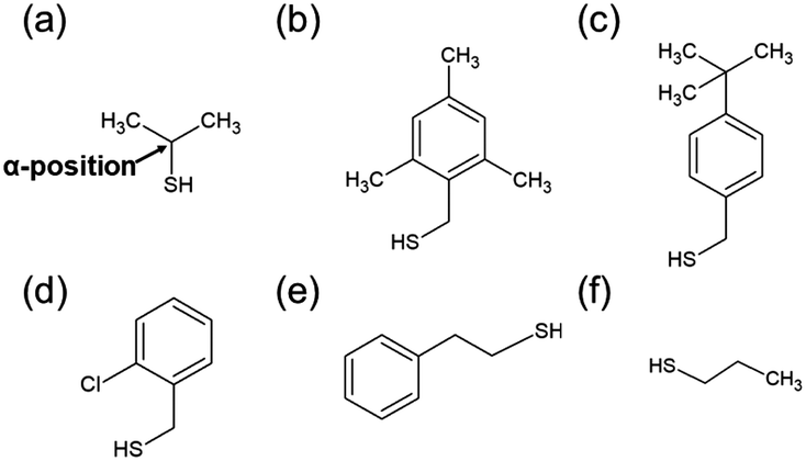 | ||
| Scheme 2 Thiols used in this study. (a) Isopropanethiol ((CH3)2CHSH), (b) 2,4,6-trimethylbenzylmercaptane ((CH3)3PhCH2SH), (c) 4-tert-butylbenzylmercaptane (tBuPhCH2SH), (d) 2-chlorobenzenemethanethiol (ClPhCH2SH), (e) 2-phenylethanethiol (PhC2H4SH), and (f) 1-propanethiol (C3H7SH). | ||
Fig. 1 shows the matrix-assisted laser desorption/ionization (MALDI) mass spectra of the products (a–f). In all mass spectra, only peaks attributed to Au4Pt2(SR)8 (SR = SCH(CH3)2 (a), SCH2Ph(CH3)3 (b), SCH2PhtBu (c), SCH2PhCl (d), SC2H4Ph (e), and SC3H7 (f)) were observed. The electrospray ionization mass spectra of a–f (Fig. S2, ESI†) showed peaks from neutral [Au4Pt2(SR)8]0 ([Au4Pt2(SR)8Cs]+; SR = SCH(CH3)2 (a), SCH2Ph(CH3)3 (b), SCH2PhtBu (c), SCH2PhCl (d), SC2H4Ph (e), and SC3H7 (f)). These results indicate that (i) [Au4Pt2(SR)8]0 are stable SR-protected Au–Pt alloy clusters (the main products)7,45 (Fig. S3, ESI†) and (ii) six kinds of [Au4Pt2(SR)8]0 (SR = SCH(CH3)2 (a), SCH2Ph(CH3)3 (b), SCH2PhtBu (c), SCH2PhCl (d), SC2H4Ph (e), and SC3H7 (f)) were isolated in high purity.
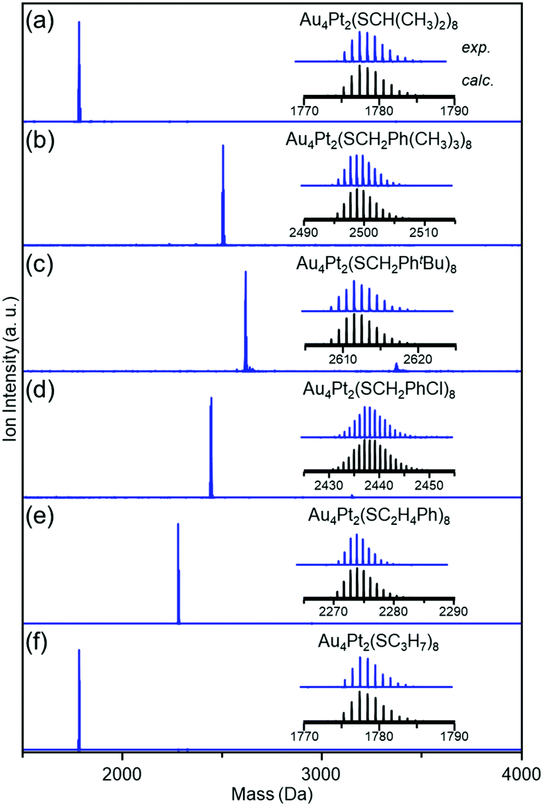 | ||
| Fig. 1 Positive-ion MALDI mass spectra of [Au4Pt2(SR)8]0 clusters with SR of (a) SCH(CH3)2, (b) SCH2Ph(CH3)3, (c) SCH3PhtBu, (d) SCH2PhCl, (e) SC2H4Ph, and (f) SC3H7. | ||
The geometric structures of a–f were investigated by single-crystal X-ray diffraction (SCXRD). All single crystals were grown by the vapor diffusion (Fig. S4 and Table S2, ESI†). Block-like crystals were obtained for a–c and needle-like crystals were obtained for d–f (Fig. S5, ESI†). SCXRD data for a–e contained little disorder. Conversely, a high degree of disorder was observed in the structure of f, which prevented us from determining its geometrical structure.
Fig. 2 shows the geometrical structures of individual a–e clusters. In each cluster, eight SR groups were bridged around an octahedral structure composed of six metal atoms. Because Au and Pt have similar numbers of electrons (79 for Au and 78 for Pt), it was difficult to identify the positions of each of these elements in the alloy clusters by SCXRD analysis alone. However, Au forms linear bonds with two SR, and Pt forms planar bonds with four SR.46 Based on these known bonding modes, we assumed that the metal atoms bonded to two SR in a linear form are Au and the metal atoms bonded to four SR to form a planar structure are Pt (Fig. 2). Overall, these geometric structures are similar to those adopted by other metals, such as [Ag4M2(DMSA)4]0 (M = nickel (Ni),47 Pd,48 or Pt;49 DMSA = dimercaptosuccinic acid), [Ag4Ni2(SPhMe2)8]0 (SPhMe2 = 2,4-dimethylbenzenethiolate),50 and [Au4Pd2(SC2H4Ph)8]0.42 In [Au4Pt2(SR)8]0, the distance between adjacent gold atoms (Au–Au) is 3.16–3.39 Å (Fig. S6, S7A, S8 and Table S3, ESI†). Although these distances are longer than the Au–Au bond length in bulk Au (2.88 Å), they are shorter than the non-bonding distance of 3.80 Å estimated based on the van der Waals radius of Au.37,51 This indicates that the Au atoms interact with each other in [Au4Pt2(SR)8]0; in other words, chemical bonds exist between Au atoms in each cluster. Similarly, although the distance between Au and Pt (3.23–3.48 Å; Fig. S6, S7B, S9 and Table S4, ESI†) is longer than the Au–Pt distance (2.72 Å) estimated from the covalent bond radii of Au and Pt52 in [Au4Pt2(SR)8]0, it is shorter than the non-bonding distance of 4.15 Å estimated from the van der Waals radii of these elements.53 This indicates that an interaction, that is, a chemical bond, exists between Au and Pt atoms in [Au4Pt2(SR)8]0. Based on these results, [Au4Pt2(SR)8]0 can be considered to be SR-protected Au–Pt alloy cluster with bonds between metal atoms (Fig. S10 and S11, ESI†).
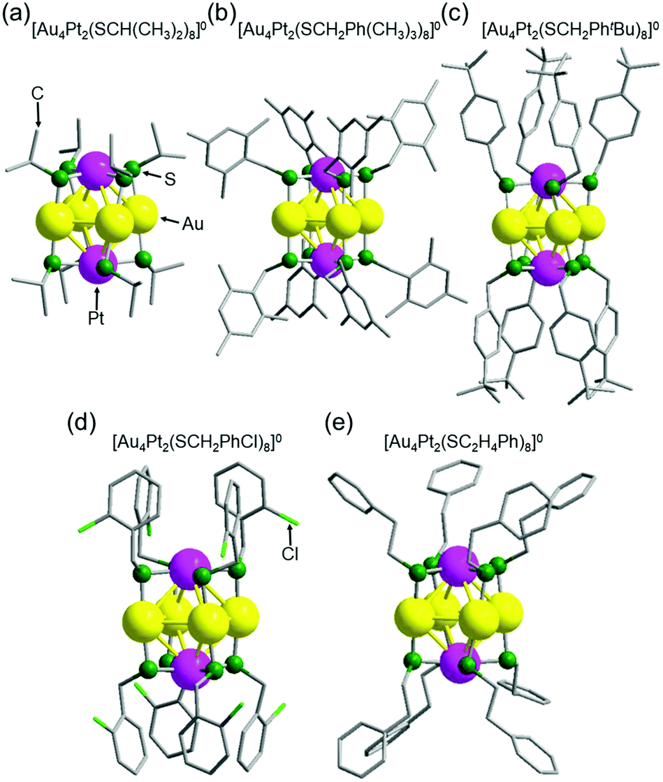 | ||
| Fig. 2 Geometrical structures of individual [Au4Pt2(SR)8]0 clusters a–e with SR of (a) SCH(CH3)2, (b) SCH2Ph(CH3)3, (c) SCH2PhtBu, (d) SCH2PhCl, and (e) SC2H4Ph. | ||
In these [Au4Pt2(SR)8]0, the ligands of a, b and e are distributed in a comparatively isotropic manner. Therefore, it was assumed that no substantial intra-cluster ligand interactions or repulsive intra-cluster ligand interactions occurred for these clusters (Fig. 2 and Table S5, ESI†). In contrast, the ligands grouped together in a relatively compact manner above and below the metal core in c and d, forming anisotropic distributions. In these clusters, the phenyl groups of the ligands around the metal core were attracted to each other,54 leading to the formation of anisotropic ligand distributions (Fig. 2 and Fig. S12, ESI†). These results indicate that in [Au4Pt2(SR)8]0, the ligand structure affects the intra-cluster ligand interactions and thereby the ligand distribution on the cluster surface. Further structural analysis also revealed that a, c, d, and e have enantiomers because of several factors (Fig. S13–S16 and Table S5, ESI†),42 whereas b does not have due to the symmetry of the geometrical structure (Fig. S17, ESI†).
Fig. 3 shows the relationship between adjacent [Au4Pt2(SR)8]0 clusters in the unit cells of a–e (Fig. S18 and S19, ESI†). In a, b, and c, the inter-cluster Au–Au distances were estimated to be 5.94, 10.2, and 9.69 Å, respectively (Fig. 3B). For these structures, we cannot consider that Au–Au bonds exist between adjacent clusters. Conversely, for d and e, the inter-cluster Au–Au distances are in the range of 2.88–3.08 Å (Fig. 3B). These Au–Au distances are shorter than the non-bonding distance of 3.80 Å estimated from the relevant van der Waals radius and close to the Au–Au distance of bulk Au (2.88 Å). Thus, we can consider that for d and e, 1D-CS formed in the single crystals via inter-cluster Au–Au bonds (aurophilic bond).
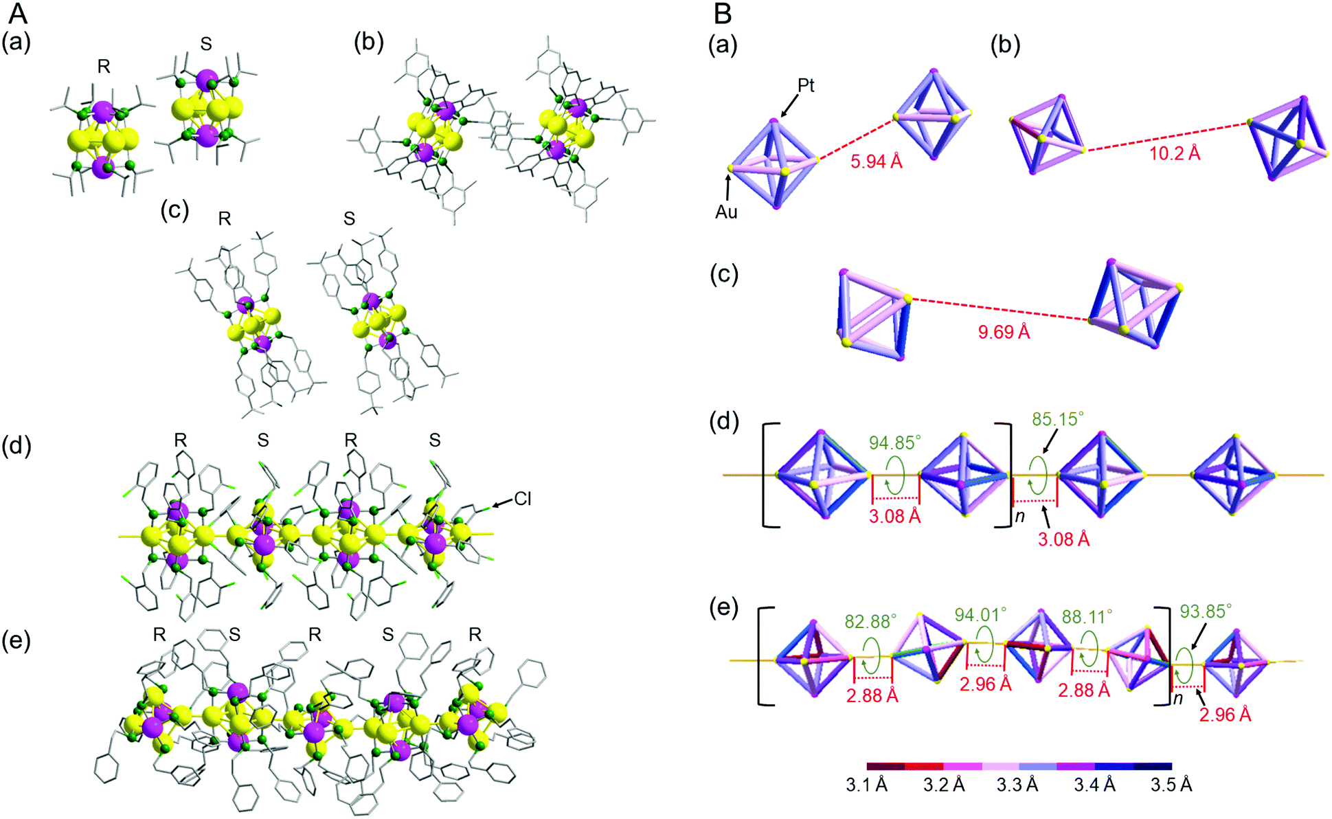 | ||
| Fig. 3 (A) Full structures and (B) Au4Pt2 core structures showing the relation between the adjacent clusters for a–e; [Au4Pt2(SR)8]0 (SR = (a) SCH(CH3)2, (b) SCH2Ph(CH3)3, (c) SCH2PhtBu, (d) SCH2PhCl and (e) SC2H4Ph). In (A), R and S indicates the two enantiomers in each cluster (Fig. S13–S16, ESI†). In (B), inter-cluster distances in 1D-CS (red values), rotation angles in 1D-CS (green values), structural units for 1D-CS (square brackets), and bond lengths in each cluster (bond color) are shown for a–e. | ||
Thus, the formation of 1D-CS of [Au4Pt2(SR)8]0 depends on the ligand structure (Table S5, ESI†). Furthermore, detailed analysis revealed that the linkage pattern in the 1D-CS also depended on the ligand structure. For example, when we compare the 1D-CS of d and e, they both have enantiomers, with the R and S forms alternating with each other in the 1D-CS (Fig. 3A(d) and (e)). These structures also contain [Au4Pt2(SR)8]0 connected at a rotation angle of nearly 90° to minimize steric repulsion between adjacent clusters (Fig. 3B(d) and (e)). However, slight differences exist between d and e in terms of inter-cluster distance and connection rotation angle (Fig. 3B(d) and (e)). For example, the 1D-CS of d is characterized by only one inter-cluster Au–Au bond length (3.08 Å) and two different connection rotation angles (85.15° and 94.85°). The formation of this structure is probably related to the fact that the 1D-CS of d contains two [Au4Pt2(SCH2PhCl)8]0 clusters in each repeating unit (Fig. 3B(d)). In this 1D-CS, clusters are arranged in a nearly straight row. Conversely, the 1D-CS of e is characterized by two different inter-cluster Au–Au bond lengths (2.88 and 2.96 Å) and four connection rotation angles (82.88°, 88.11°, 93.85°, and 94.01°). This 1D-CS contains four [Au4Pt2(SC2H4Ph)8]0 clusters with a slight ‘zigzag’ arrangement per repeating unit (Fig. 3B(e)). These results demonstrate that small differences exist between the bond lengths and bond angles in the 1D-CS of d and e. As mentioned above, no strong intra-cluster ligand interactions occurred in e (Fig. 2(e) and Fig. S12, ESI†). In addition, the carbon chain connecting the sulfur atom and Ph group is longer in the ligand of e than in that of d (–C2H4– vs. –CH2–; Scheme 2(d) and (f)). Therefore, e is presumed to be more flexible than d in the direction of ligand extension and also in its geometric structure. It seems that e can shorten the inter-cluster Au–Au distance in its 1D-CS for these reasons, leading to the wide distribution of intra-cluster metal–metal bond lengths in [Au4Pt2(SR)8]0 (Fig. S6–S8 and Table S3, S4, ESI†).
According to this interpretation, we reached the conclusion that a ligand causing an appropriate inter-cluster ligand interaction should be used to form 1D-CS (Fig. 4).37,38 Because the ligands in d and e contain a Ph group, π–π interactions are induced between the adjacent clusters (Fig. 4B). The steric repulsion caused by the inclusion of the Ph group is minimized by the linkage possessing a rotation angle of nearly 90°. Based on these facts, the ligands of d and e are considered to be appropriate for the formation of 1D-CS (Fig. 4C). The ligand of a is different to those of d and e. Because this ligand has no Ph group, it cannot induce strong attractive interactions between adjacent clusters. In addition, although the ligand in a is not long, the α carbon atom is a secondary carbon. Thus, steric repulsion should easily arise between the adjacent clusters (Fig. 4B). It is considered that a did not form a 1D-CS for these two reasons (Fig. 4C).
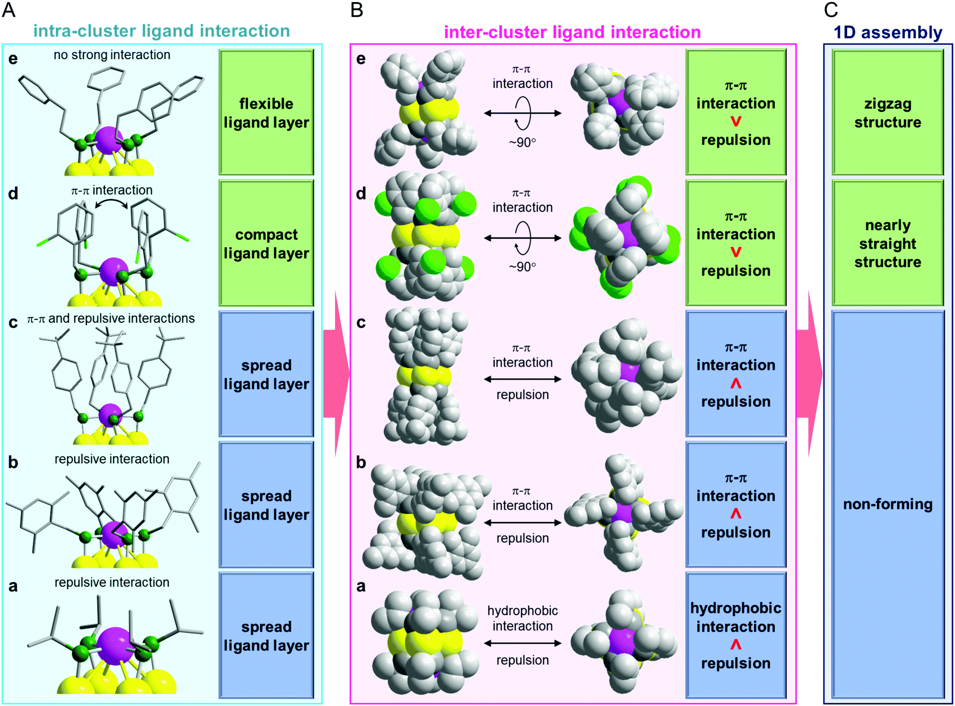 | ||
| Fig. 4 Relationship between (A) intra-cluster ligand interaction which is related to the distribution of the ligands within each cluster, (B) inter-cluster ligand interaction and (C) 1D assembly for a–e. | ||
Regarding the correlation between the ligand structure and the formation of a 1D-CS, the relationship in b–d is interesting. All of the relevant ligands (Scheme 2(b)–(d)) in this series have a phenylmethanethiolate (SCH2Ph) moiety in their skeleton. Nevertheless, d formed a 1D-CS, whereas b and c did not (Fig. 3). These differences are assumed to result mainly from their different intra-cluster ligand interactions (Fig. 4A). In b, because three methyl groups are bound to the Ph group, the Ph groups cannot get close to each other, so the ligands of b distribute isotropically (Fig. 4A). It can be considered that b did not form a 1D-CS because of the strong steric repulsion between the clusters with this geometry (Fig. 4B and C). Conversely, in c and d, the Ph groups are grouped above and below the Au4 plane because of their π–π interactions (Fig. 4A and Fig. S12(c), (d), ESI†). However, close analysis revealed that the ligand assembly in c was slightly expanded because of the steric repulsion between the t-butyl groups (Fig. 2(c) and Fig. S12(c), ESI†), whereas the ligand assembly in d adopted a more compact structure with Cl oriented to the outside of the ligand layer (Fig. 2(d) and Fig. S12(d), ESI†). It is considered that unlike d, c could not form a 1D-CS because of the slight expansion of the ligand assembly (Fig. 4).
In this way, the formation of 1D-CS and their geometric structures are governed by the balance between attractive forces and steric repulsion caused by inter-cluster ligand interactions (Fig. 4B and C). In addition, the ligand distribution, which influences inter-cluster ligand interactions, is strongly related to intra-cluster ligand interactions (Fig. 4A). These results indicate that if we want to fabricate a 1D-CS with a desired connecting structure, we need to design the intra-cluster ligand interactions.
It should be noted that both intra- and inter-cluster ligand interactions also closely related to the geometric structure of the metal core of the clusters. Therefore, to connect clusters with different metal core structures, we should design the ligand structure based on different guidelines. Actually, one of [Au25(SR)18]0 clusters, [Au25(SC2H4Ph)18]0, does not form a 1D-CS.55 The metal core framework of [Au25(SR)18]0 is larger than that of [Au4Pt2(SR)8]0 and thus [Au25(SR)18]0 has less freedom in the direction of ligand extension. It is considered that [Au25(SC2H4Ph)18]0 does not form a 1D-CS because the steric repulsion between adjacent [Au25(SC2H4Ph)18]0 cannot be avoided even at a rotation angle of 90°.
Fig. 5 shows the optical absorption spectra of a–e. In this figure, the dry state indicates the amorphous films. In all cases, the spectra obtained in the solution phase and dry state were very similar to each other, indicating the dissolved and dry states possess similar electronic structures (Fig. S20 and Table S6, ESI†). Conversely, in the crystalline state, the onset of optical absorption occurred at longer wavelength than the case in solution and solid states. This observation indicates that crystallization changed the electronic structure of a–e.56
 | ||
| Fig. 5 Optical absorption spectra of a–e ([Au4Pt2(SR)8]0 with SR of (a) SCH(CH3)2, (b) SCH2Ph(CH3)3, (c) SCH2PhtBu, (d) SCH2PhCl, and (e) SC2H4Ph) in dichloromethane solution (blue lines), dried samples (green lines), and crystals (red lines). The spectra below 400 nm were not observed at high quality because this region also contained the absorption of the barium sulfate substrate. In these spectra, the absorption of each sample is normalized at 400 nm. | ||
To elucidate whether these changes in electronic structure accompanying crystallization included the effect of the formation of 1D-CS, we examined the electronic structures of individual d and e and their 1D-CS by DFT calculations. The experimentally obtained geometric structure shown in Fig. 4 was used as the structure of the individual units and 1D-CS (Fig. S21, ESI†).
Fig. 6A shows the projected density of states of individual e. The gap between the highest occupied molecular orbital (HOMO) and lowest unoccupied molecular orbital (LUMO) obtained by DFT calculation was 2.93 eV, which is consistent with that estimated from the optical absorption spectrum (2.82 eV; Fig. S22A, ESI†). Fig. 7A depicts the HOMO and LUMO states of individual e. The HOMO is mainly composed of Au 5d, Pt 5d, and S 2p orbitals, whereas the LUMO is mainly composed of Pt 5d and S 2p orbitals (Fig. 6A). Overall, the origins of these HOMO and LUMO are in good agreement with those of [Au4Pd2(SC2H5)8]0.42
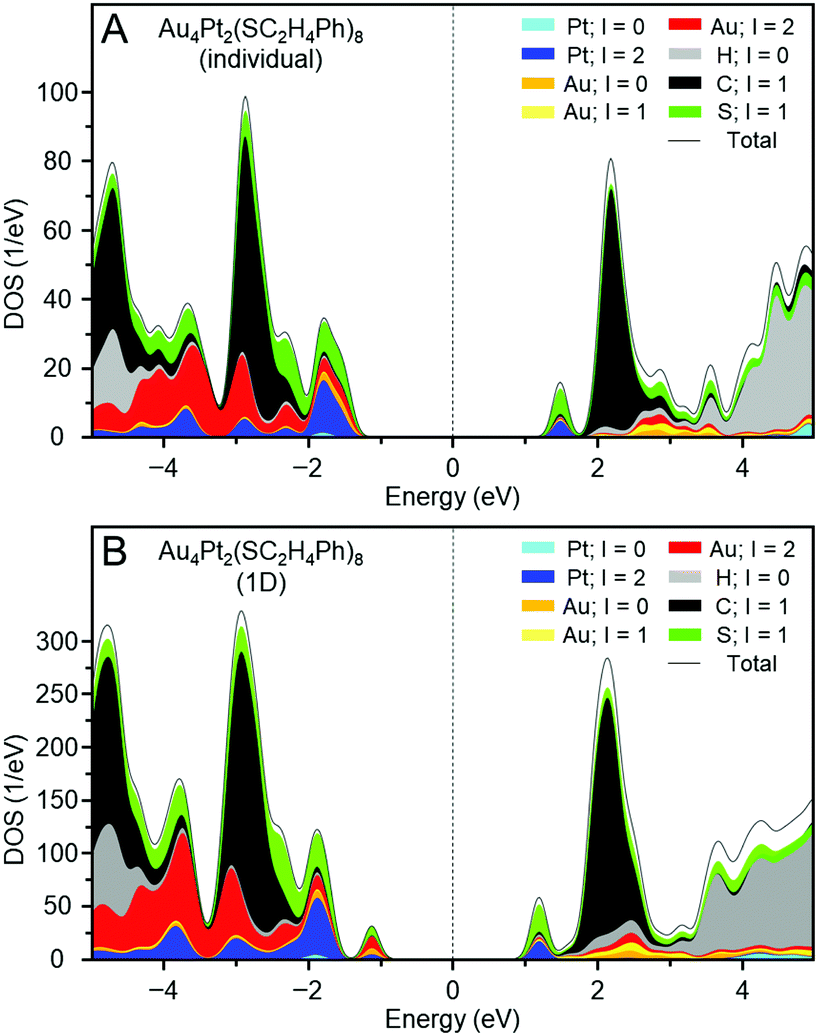 | ||
| Fig. 6 Projected density of states of (A) an individual e and (B) the 1D-CS of e. | ||
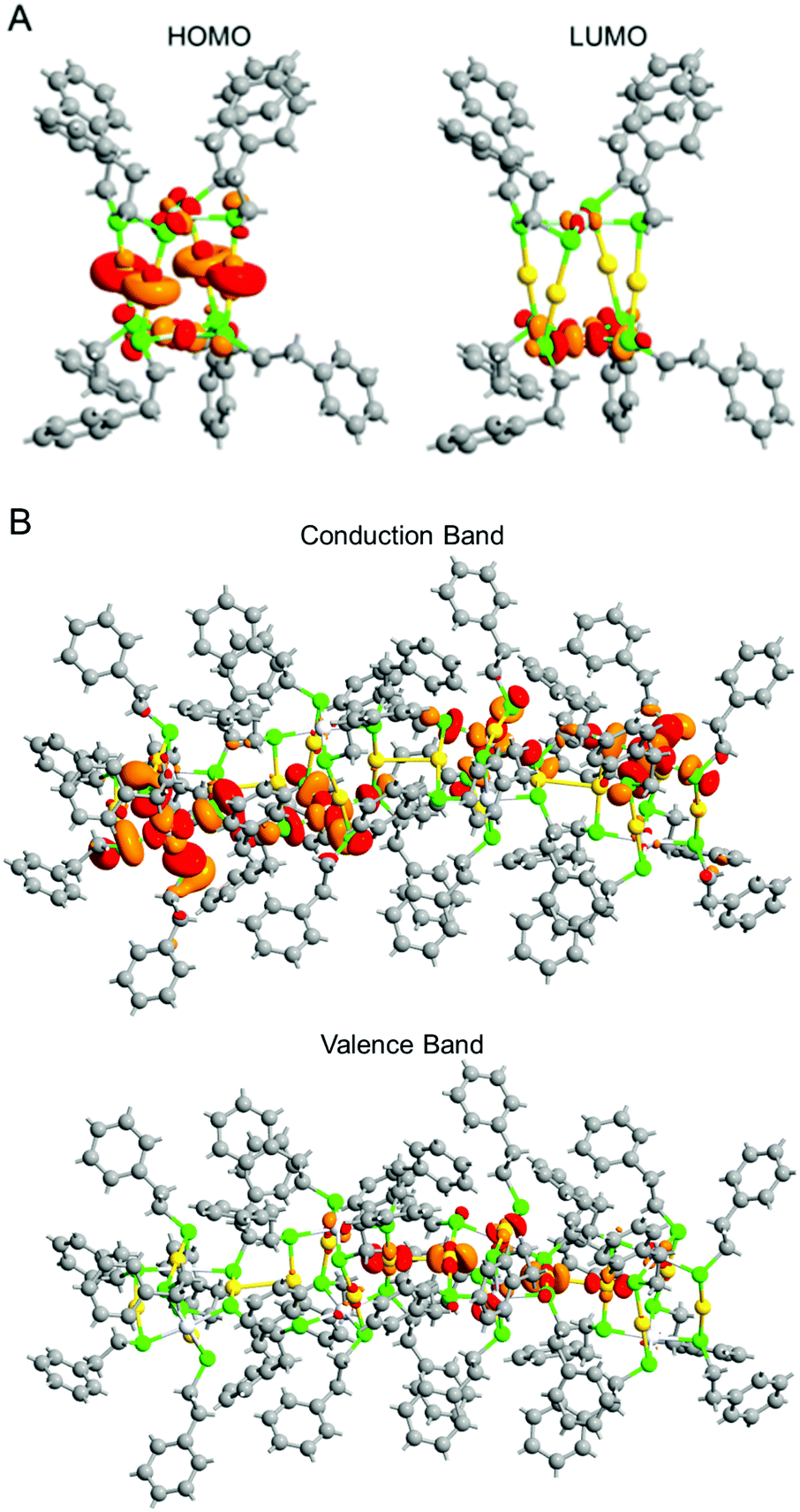 | ||
| Fig. 7 (A) HOMO (left) and LUMO (right) states of an individual e and (B) Γ-point Bloch wave functions for the conduction band minimum and valence band maximum of the 1D-CS of e. | ||
Fig. 6B shows the projected density of states of the 1D-CS of e. These are generally very similar to those of the individual e cluster. From these data, it is concluded that e generally maintains the electronic structure of each [Au4Pt2(SC2H4Ph)8]0 in its 1D-CS. In contrast, the gap between the valence and conduction bands of the 1D-CS (2.17 eV) was narrower than the HOMO–LUMO gap (2.93 eV) of individual e (Fig. S22B, ESI†). This indicates that the formation of the 1D-CS narrows the band gap of e. As mentioned earlier, the HOMO of e contains orbitals originating from Au 5d. Therefore, when inter-cluster Au–Au bonds are formed in the 1D-CS, the valence band composed of the HOMO is greatly affected (Fig. 7B) and thereby the valence band splits into two (Fig. 6B). It is considered that the formation of the 1D-CS induces the decrease in the band gap, because the orbital energy at the top end of the valence band increases due to the splitting of the valence band. It is interpreted that formation of a 1D-CS also induces a decrease of the band gap of d for similar reasons (Fig. S23–S25, ESI†). Although other reason seems to be also related to the phenomenon seen in Fig. 5, the result of DFT study strongly implies that the formation of 1D-CS is one of the reasons of the decrease of HOMO–LUMO gap accompanying crystallization (Fig. S26, ESI†).
Conclusions
We investigated the correlation between the ligand structure, geometrical structure of individual clusters, and formation and geometry of 1D-CS for [Au4Pt2(SR)8]0 clusters. The results clarified the following four points:(1) [Au4Pt2(SR)8]0 can serve as a building block for 1D-CS constructed via the formation of inter-cluster Au–Au bonds.
(2) Occurrence or absence of 1D-CS formation and the connection angles in 1D-CS are governed by the balance between attractive forces and steric repulsion caused by inter-cluster ligand interactions.
(3) Inter-cluster ligand interactions also depend on the intra-cluster ligand interactions.
(4) Formation of 1D-CS narrows the band gap of the clusters.
These results demonstrate that it is necessary to control intra-cluster ligand interactions to obtain 1D-CS with the desired linkage structures. This finding is expected to lead to clear design guidelines for the fabrication of metal cluster assemblies with targeted assembled structures.
Author contributions
Y. Negishi and S. Hossain designed the experiments and conducted the measurements along with Z. Chen, Y. Imai, T. Suzuki, D. Suzuki, Y. Kataoka, M. Hirata, T. Ono, W. Kurashige, and T. Kawawaki. Y. Motohashi and T. Yamamoto performed DFT calculations. Y. Negishi and S. Hossain wrote the paper. All authors have approved the final version of the manuscript.Conflicts of interest
There are no conflicts to declare.Acknowledgements
We thank Yoshihisa Sei (Tokyo Institute of Technology) and Ms Mai Hosoi (Tokyo University of Science) for technical assistance. This work was supported by the Japan Society for the Promotion of Science (JSPS) KAKENHI (grant number JP16H04099 and 16K21402) and Grants-in-Aid for Scientific Research on Innovative Areas “Coordination Asymmetry” (grant number 17H05385) and “Innovations for Light-Energy Conversion” (grant number 18H05178). Funding from Asahi Glass Foundation is also gratefully acknowledged.References
- T. Tsukuda and H. Häkkinen, Protected Metal Clusters: From Fundamentals to Applications, B. V. Elsevier, Amsterdam, The Netherlands, 2015 Search PubMed.
- M. Brust, M. Walker, D. Bethell, D. J. Schiffrin and R. Whyman, J. Chem. Soc., Chem. Commun., 1994, 801–802 RSC.
- R. Jin, C. Zeng, M. Zhou and Y. Chen, Chem. Rev., 2016, 116, 10346–10413 CrossRef CAS PubMed.
- H. Qian, M. Zhu, Z. Wu and R. Jin, Acc. Chem. Res., 2012, 45, 1470–1479 CrossRef CAS PubMed.
- I. Chakraborty and T. Pradeep, Chem. Rev., 2017, 117, 8208–8271 CrossRef CAS PubMed.
- Q. Yao, T. Chen, X. Yuan and J. Xie, Acc. Chem. Res., 2018, 51, 1338–1348 CrossRef CAS PubMed.
- S. Hossain, Y. Niihori, L. V. Nair, B. Kumar, W. Kurashige and Y. Negishi, Acc. Chem. Res., 2018, 51, 3114–3124 CrossRef CAS PubMed.
- K. Kwak and D. Lee, Acc. Chem. Res., 2019, 52, 12–22 CrossRef CAS PubMed.
- N. A. Sakthivel and A. Dass, Acc. Chem. Res., 2018, 51, 1774–1783 CrossRef CAS PubMed.
- R. L. Whetten, H.-C. Weissker, J. J. Pelayo, S. M. Mullins, X. López-Lozano and I. L. Garzón, Acc. Chem. Res., 2019, 52, 34–43 CrossRef CAS PubMed.
- M. Agrachev, M. Ruzzi, A. Venzo and F. Maran, Acc. Chem. Res., 2019, 52, 44–52 CrossRef CAS PubMed.
- Y. Pei, P. Wang, Z. Ma and L. Xiong, Acc. Chem. Res., 2019, 52, 23–33 CrossRef CAS PubMed.
- B. Bhattarai, Y. Zaker, A. Atnagulov, B. Yoon, U. Landman and T. P. Bigioni, Acc. Chem. Res., 2018, 51, 3104–3113 CrossRef CAS PubMed.
- C. M. Aikens, Acc. Chem. Res., 2018, 51, 3065–3073 CrossRef CAS PubMed.
- J. Yan, B. K. Teo and N. Zheng, Acc. Chem. Res., 2018, 51, 3084–3093 CrossRef CAS PubMed.
- A. Ghosh, O. F. Mohammed and O. M. Bakr, Acc. Chem. Res., 2018, 51, 3094–3103 CrossRef CAS PubMed.
- B. Nieto-Ortega and T. Bürgi, Acc. Chem. Res., 2018, 51, 2811–2819 CrossRef CAS PubMed.
- Q. Tang, G. Hu, V. Fung and D.-e. Jiang, Acc. Chem. Res., 2018, 51, 2793–2802 CrossRef CAS PubMed.
- Z. Gan, N. Xia and Z. Wu, Acc. Chem. Res., 2018, 51, 2774–2783 CrossRef CAS PubMed.
- W. Kurashige, Y. Niihori, S. Sharma and Y. Negishi, J. Phys. Chem. Lett., 2014, 5, 4134–4142 CrossRef CAS PubMed.
- Y. Song, S. Wang, J. Zhang, X. Kang, S. Chen, P. Li, H. Sheng and M. Zhu, J. Am. Chem. Soc., 2014, 136, 2963–2965 CrossRef CAS PubMed.
- Z. Lei, X.-K. Wan, S.-F. Yuan, Z.-J. Guan and Q.-M. Wang, Acc. Chem. Res., 2018, 51, 2465–2474 CrossRef CAS PubMed.
- K. Konishi, M. Iwasaki and Y. Shichibu, Acc. Chem. Res., 2018, 51, 3125–3133 CrossRef CAS PubMed.
- Q.-F. Zhang, X. Chen and L.-S. Wang, Acc. Chem. Res., 2018, 51, 2159–2168 CrossRef CAS PubMed.
- I. Ciabatti, C. Femoni, M. C. Iapalucci, S. Ruggieri and S. Zacchini, Coord. Chem. Rev., 2018, 355, 27–38 CrossRef CAS.
- E. G. Mednikov, M. C. Jewell and L. F. Dahl, J. Am. Chem. Soc., 2007, 129, 11619–11630 CrossRef CAS PubMed.
- J. Xie, Y. Zheng and J. Y. Ying, Chem. Commun., 2010, 46, 961–963 RSC.
- H. Kawasaki, S. Kumar, G. Li, C. Zeng, D. R. Kauffman, J. Yoshimoto, Y. Iwasaki and R. Jin, Chem. Mater., 2014, 26, 2777–2788 CrossRef CAS.
- G. Li and R. Jin, Acc. Chem. Res., 2013, 46, 1749–1758 CrossRef CAS PubMed.
- Y. Negishi, Y. Matsuura, R. Tomizawa, W. Kurashige, Y. Niihori, T. Takayama, A. Iwase and A. Kudo, J. Phys. Chem. C, 2015, 119, 11224–11232 CrossRef CAS.
- W. Kurashige, R. Kumazawa, D. Ishii, R. Hayashi, Y. Niihori, S. Hossain, L. V. Nair, T. Takayama, A. Iwase, S. Yamazoe, T. Tsukuda, A. Kudo and Y. Negishi, J. Phys. Chem. C, 2018, 122, 13669–13681 CrossRef CAS.
- N. Sakai and T. Tatsuma, Adv. Mater., 2010, 22, 3185–3188 CrossRef CAS PubMed.
- Y.-S. Chen, H. Choi and P. V. Kamat, J. Am. Chem. Soc., 2013, 135, 8822–8825 CrossRef CAS PubMed.
- S. Tian, L. Liao, J. Yuan, C. Yao, J. Chen, J. Yang and Z. Wu, Chem. Commun., 2016, 52, 9873–9876 RSC.
- S. Kano, Y. Azuma, M. Kanehara, T. Teranishi and Y. Majima, Appl. Phys. Express, 2010, 3, 105003 CrossRef.
- D.-e. Jiang, K. Nobusada, W. Luo and R. L. Whetten, ACS Nano, 2009, 3, 2351–2357 CrossRef CAS PubMed.
- M. D. Nardi, S. Antonello, D.-e. Jiang, F. Pan, K. Rissanen, M. Ruzzi, A. Venzo, A. Zoleo and F. Maran, ACS Nano, 2014, 8, 8505–8512 CrossRef PubMed.
- S. Antonello, T. Dainese, F. Pan, K. Rissanen and F. Maran, J. Am. Chem. Soc., 2017, 139, 4168–4174 CrossRef CAS PubMed.
- W. Fei, S. Antonello, T. Dainese, A. Dolmella, M. Lahtinen, K. Rissanen, A. Venzo and F. Maran, J. Am. Chem. Soc., 2019, 141, 16033–16045 CrossRef CAS PubMed.
- Z.-R. Wen, Z.-J. Guan, Y. Zhang, Y.-M. Lin and Q.-M. Wang, Chem. Commun., 2019, 55, 12992–12995 RSC.
- X. Kang, H. Chong and M. Zhu, Nanoscale, 2018, 10, 10758–10834 RSC.
- J. Chen, L. Liu, X. Liu, L. Liao, S. Zhuang, S. Zhou, J. Yang and Z. Wu, Chem. – Eur. J., 2017, 23, 18187–18192 CrossRef CAS PubMed.
- D.-e. Jiang and S. Dai, Inorg. Chem., 2009, 48, 2720–2722 CrossRef CAS PubMed.
- H. Qian, D.-e. Jiang, G. Li, C. Gayathri, A. Das, R. R. Gil and R. Jin, J. Am. Chem. Soc., 2012, 134, 16159–16162 CrossRef CAS PubMed.
- W. Kurashige, Y. Niihori, S. Sharma and Y. Negishi, Coord. Chem. Rev., 2016, 320–321, 238–250 CrossRef CAS.
- M. K. Corbierre and R. B. Lennox, Chem. Mater., 2005, 17, 5691–5696 CrossRef CAS.
- S. R. Biltek, S. Mandal, A. Sen, A. C. Reber, A. F. Pedicini and S. N. Khanna, J. Am. Chem. Soc., 2013, 135, 26–29 CrossRef CAS PubMed.
- S. R. Biltek, A. C. Reber, S. N. Khanna and A. Sen, J. Phys. Chem. A, 2017, 121, 5324–5331 CrossRef CAS PubMed.
- S. R. Biltek, A. Sen, A. F. Pedicini, A. C. Reber and S. N. Khanna, J. Phys. Chem. A, 2014, 118, 8314–8319 CrossRef CAS PubMed.
- G. Sun, X. Kang, S. Jin, X. Li, D. Hu, S. Wang and M. Zhu, Acta Phys.-Chim. Sin., 2018, 34, 0001–0009 Search PubMed.
- H. Schmidbaur and A. Schier, Chem. Soc. Rev., 2012, 41, 370–412 RSC.
- B. Cordero, V. Gómez, A. E. Platero-Prats, M. Revés, J. Echeverría, E. Cremades, F. Barragán and S. Alvarez, Dalton Trans., 2008, 2832–2838 RSC.
- S. S. Batsanov, Inorg. Mater., 2001, 37, 871–885 CrossRef CAS.
- S. Hossain, Y. Imai, D. Suzuki, W. Choi, Z. Chen, T. Suzuki, M. Yoshioka, T. Kawawaki, D. Lee and Y. Negishi, Nanoscale, 2019, 11, 22089–22098 RSC.
- M. Zhu, C. M. Aikens, F. J. Hollander, G. C. Schatz and R. Jin, J. Am. Chem. Soc., 2008, 130, 5883–5885 CrossRef CAS PubMed.
- M. J. Alhilaly, R.-W. Huang, R. Naphade, B. Alamer, M. N. Hedhili, A.-H. Emwas, P. Maity, J. Yin, A. Shkurenko, O. F. Mohammed, M. Eddaoudi and O. M. Bakr, J. Am. Chem. Soc., 2019, 141, 9585–9592 CrossRef CAS PubMed.
Footnote |
| † Electronic supplementary information (ESI) available: Experimental section, bond lengths, the values of HOMO–LUMO gap, additional mass spectra, photographs of crystals, XPS spectra, enantiomer, additional theoretical results crystal data. CCDC 1956250–1956254. For ESI and crystallographic data in CIF or other electronic format see DOI: 10.1039/c9mh01691k |
| This journal is © The Royal Society of Chemistry 2020 |