
 Open Access Article
 This Open Access Article is licensed under a Creative Commons Attribution-Non Commercial 3.0 Unported Licence
About the amplification factors in organic bioelectronic sensors
Eleonora
Macchia
 ab,
Rosaria Anna
Picca
ac,
Kyriaki
Manoli
ac,
Cinzia
Di Franco
d,
Davide
Blasi
c,
Lucia
Sarcina
ab,
Nicoletta
Ditaranto
a,
Nicola
Cioffi
ab,
Ronald
Österbacka
d,
Gaetano
Scamarcio
de,
Fabrizio
Torricelli
cf and
Luisa
Torsi
*abc
ab,
Rosaria Anna
Picca
ac,
Kyriaki
Manoli
ac,
Cinzia
Di Franco
d,
Davide
Blasi
c,
Lucia
Sarcina
ab,
Nicoletta
Ditaranto
a,
Nicola
Cioffi
ab,
Ronald
Österbacka
d,
Gaetano
Scamarcio
de,
Fabrizio
Torricelli
cf and
Luisa
Torsi
*abc
aDipartimento di Chimica, Università degli Studi di Bari “Aldo Moro”, 70125 Bari, Italy. E-mail: luisa.torsi@uniba.it
bPhysics and Center for Functional Materials, Faculty of Science and Engineering, Åbo Akademi University, 20500 Turku, Finland
cCentre for Colloid and Surface Science, Università degli Studi di Bari “Aldo Moro”, 70125 Bari, Italy
dCNR, Istituto di Fotonica e Nanotecnologie, Sede di Bari, Italy
eDipartimento di Fisica “M. Merlin”, Università degli Studi di Bari “Aldo Moro”, 70125 Bari, Italy
fDipartimento Ingegneria dell’Informazione, Università degli Studi di Brescia, 25123 Brescia, Italy
First published on 13th January 2020
Abstract
Several three-terminal organic bioelectronic structures have been proposed so far to address the needs for a variety of biosensing applications. The most popular ones utilized organic field-effect transistors operated in an electrolyte, to detect both proteins and genomic analytes. They are endowed with selectivity by immobilizing a layer of bio-recognition elements. These features along with the foreseen low-cost for their production, make them very appealing for point-of-care biomedical applications. However, organic bioelectronic transistors do not always exhibit a performance level beyond state-of-the-art electrochemical sensors, which have been dominating the field for decades. This review offers a perspective view based on a systematic comparison between the potentiometric and amperometric electrochemical sensors and their organic bioelectronic transistor counterparts. The key-relevant aspects of the sensing mechanisms are reviewed for both, and when the mathematical analytical expression is actually available, the amplification factors are reported as the ratio between the response of a rationally designed transistor (or amplifying circuit) and that of a homologous electrochemical sensor. The functional dependence of the bioelectronic sensor responses on the concentration of the species to be detected enabling their correct analytical quantification, is also addressed.
 Eleonora Macchia | Eleonora Macchia has been a project researcher at Åbo Akademi University since March 2019. She was a Postdoctoral fellow at the University of Bari and received her PhD in Chemical Sciences summa cum laude in 2018 from the same University. Her Master's degree in Physics, 110/110 cum laude, was awarded in 2014 from the same institution. At the age of 29 she has published 19 papers in International Journals. She is also a coauthor of a European Patent. She is a coauthor of three book chapters and has participated to 18 International Conferences, giving 10 oral contributions and 4 posters. She has received so far 7 scientific awards. |
 Rosaria Anna Picca | Rosaria Anna Picca is an assistant professor in Analytical Chemistry at the Chemistry Department of the University of Bari. She received the PhD in “Chemistry and physics for the environment” in 2008. Her research activities deal with the application of electrochemical and surface analytical techniques in the field of materials science, in particular for the preparation and characterization of nanostructured materials. She is also involved in the development and study of organic field-effect transistor biosensors. She is a co-author of more than 50 publications and 4 book chapters. |
 Kyriaki Manoli | Kyriaki Manoli received her BSc in Chemistry in 2003 from the University of Ioannina in Greece and her MSc and PhD in “Polymer Science and its Applications” from the Chemistry Department of the National and Kapodistrian University of Athens-Greece in 2005 and 2010 respectively. In 2011 she joined the Analytical Chemistry Department at the University of Bari as a post-doctoral fellow. Since 2016 she has been a researcher at the same department. Her research interests include fabrication and characterization of bioelectronic devices and, in particular, field-effect transistors to be used for chemical and bio-sensing applications. |
 Davide Blasi | Davide Blasi is a post doc researcher at Center for Colloid and Surface Science (CSGI) at the University of Bari. He graduated with honors in Materials Science and Technology at the University of Bari in 2013. He won a PhD grant in a Marie Skłodowska-Curie Innovative Training network, at the Materials Science Institute of Barcelona. He received his PhD in “Materials Science” with honors in 2017, with a thesis on the synthesis and characterization of highly luminescent organic free radicals for sensing applications. He is currently working on the development of ultra-sensitive biosensors based on organic field-effect transistors. |
 Fabrizio Torricelli | Fabrizio Torricelli received a DEng degree with honors and a PhD degree in Electronic Engineering from the University of Brescia, Italy, in 2006 and 2010, respectively. From 2006 to 2010, he was a consultant with the STMicroelectronics R&D group, and from 2010 to 2012, he was appointed as a Post-Doctoral Fellow at the Eindhoven University of Technology, Netherlands. He is currently an Associate Professor with the University of Brescia. His current research interests include the numerical and analytical modeling of organic transistors, and the development of new thin-film transistor architectures, as well as electrochemical and electrolyte-gated bio-sensors. |
 Luisa Torsi | Luisa Torsi is a professor of chemistry at the University of Bari and adjunct professor at Abo Academy University. She received her laurea degree in Physics and PhD in Chemical Sciences from the University of Bari and was a post-doctoral fellow at Bell Labs in USA. She is the past-president of the European Material Research Society, being the first woman to hold this role. She is also the only woman awarded with the H. E. Merck prize and she was also elected Fellow of the Material Research Society. The International Union of Pure and Applied Chemistry awarded her with the Distinguished Women Award. The analytical chemistry division of the European Chemical Society, conferred her the Robert Kellner Lecturer 2019. |
Introduction
The electronic transduction of biochemical events can be a very sensitive, selective and fast approach to biosensing; the devices can also be potentially produced as arrays using low-cost large-area fabrication technologies.1–7 Electronic biosensors can be ideal to serve as core elements in miniaturized, integrated array systems that combine detection at high performance with the delivery of an already digitally processed response. For instance, an output signal that is self-calibrated or self-compensated for spurious signals can be conceived. Such sensors do not need a labelling step to detect the analyte species so the sensing process is also faster and simpler. Taken together these characteristics make bioelectronic sensors extremely appealing for biomedical assays, particularly for point-of-care clinical tests to be performed directly where most needed, for instance at the site of patient care.4,8–12 It is therefore not at all surprising that the field of large-area and printable organic bioelectronic sensors has become very active and many different materials, device structures and systems have been proposed.Yet, not all the organic bioelectronic sensing structures appear to utilize a rational design involving a clearly identified amplification factor that enhances the electronic biosensor performance level compared to the state-of-the-art. Indeed, numerous scientific advances are dwarfs standing on the shoulders of giants and for bioelectronics the giants are the analytical electrochemical sensors whose history, encompassing decades of very successful fundamental science and technological developments up to commercialization, can be traced back to 1962.13
The aim of this review is to provide a perspective view on the rationale that should be used to design a transistor-based organic bioelectronic sensor whose response is amplified compared to that of a homologous electrochemical one detecting the same species with the same recognition element and characterized by the same geometrical factors. The discussion involves two of the most widely studied organic bioelectronic structures, namely the Electrolyte-Gated Organic Field-Effect Transistor (EGOFET)5,11,14–16 and Organic Electrochemical Transistor (OECT).17–21 Their output responses are systematically compared to those of homologous potentiometric and amperometric electrochemical biosensors, detailing not only the correct quantitative correlations with the concentration of analyte, but also elucidating the amplification factors when their mathematical expression is known. The amplification factor for a transistor (or for an amplifying circuit) is the ratio between the output and the input signal that can be a potential or a current. In line with this general definition, we are here defining the amplification as the ratio between the shift of the output signal upon sensing and the shift of the input signal. The latter being the shift that would have been measured with a homologous electrochemical biosensor. To this end, after a general introduction to biosensors, each of the four biosensing structures are reviewed in separate paragraphs and their sensing mechanisms and output response equations are detailed and compared. Specifically, the output of a potentiometric electrochemical sensor detecting a non redox-active analyte is compared to that of a homologous EGOFET while the electrochemical sensor detecting a redox-active species is compared to that of a homologous OECT. In this case both an amperometric and potentiometric detection is possible.
The essential toolbox for electrochemical biosensors
A biosensor is a device that transforms the information associated with a biochemical mechanism into a processable signal quantitatively correlated with the concentration of a target analyte. To endow the device with selectivity, a biological recognition element is integrated into the device structure to benefit from its specific interaction with the target analyte. The information coming from the biochemical domain is converted, afterwards into a chemical or physical output signal that is characterized by a given sensitivity.22–24The analytical validation of a biosensing technology is essential to gather reliable qualitative or quantitative data, on the analyte. To this end, analytical figures of merit such as selectivity, sensitivity, precision, accuracy, and limits of detection need to be assessed. These have been already operatively defined in a number of reviews on organic bioelectronic sensors;24 hence, they will not be addressed here.
A schematic of a biosensor structure is given in Fig. 1. It comprises a detecting interface to which a layer of recognition elements (e.g. antibodies, single DNA strands or enzymes) is immobilized. These recognition elements form stable compounds or selectively interact with different classes of analytes such as antigens, complementary DNA strands or the enzymes’ substrates, respectively. Hence, they endow the biosensor with selectivity.
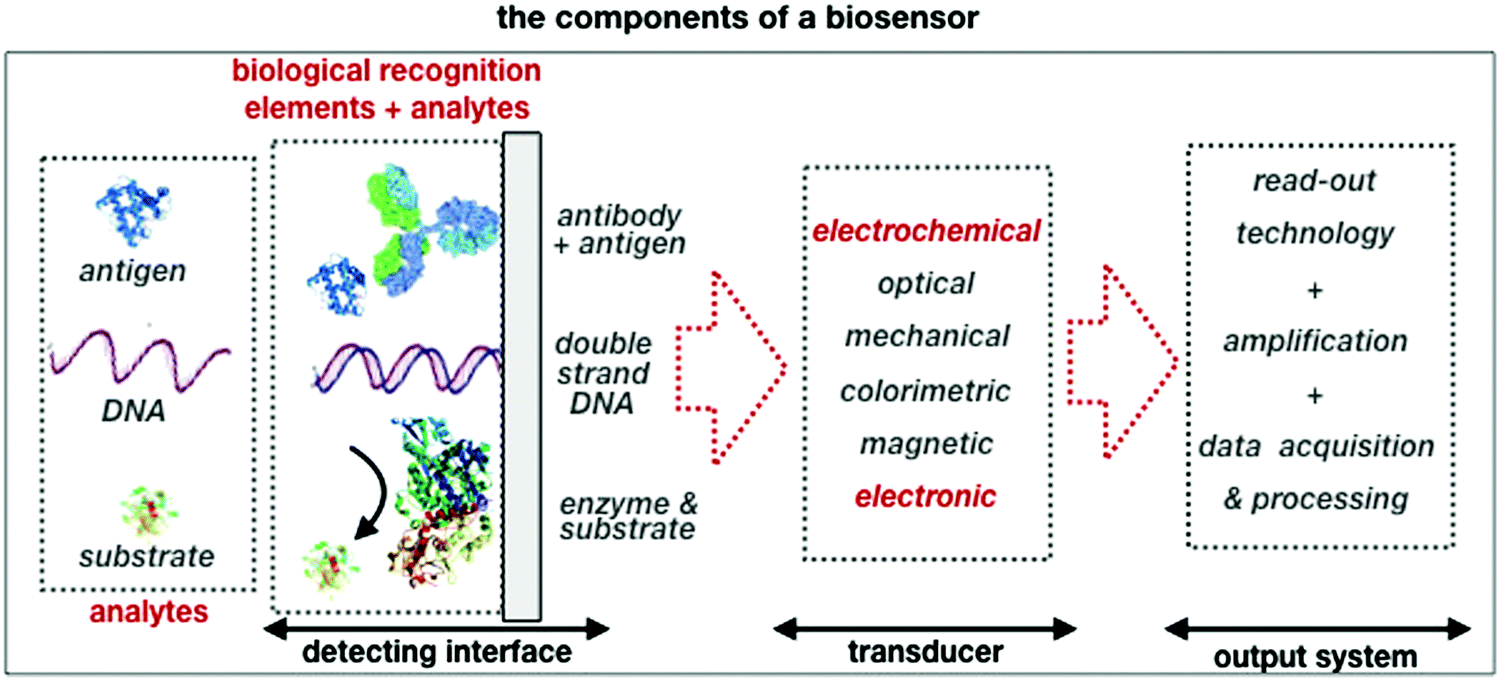 | ||
| Fig. 1 A schematic of the elements and the single components that are comprised in a typical biosensor. | ||
An electrochemical biosensor25,26 transduces into a current or a potential, the output of a biochemical reaction. According to IUPAC an electrochemical biosensor is a self-contained integrated device, which is capable of providing specific quantitative or semi-quantitative analytical information,27 even when a real biofluid containing interfering species, is assayed.
The field started with the introduction of the glucose sensor13 whose selectivity relies on the action of the glucose oxidase enzyme immobilized at the electrode surface. The enzyme exclusively interacts via a redox process (exchange of an electron) with its substrate molecule (glucose), generating a faradaic electronic current that, via the catalysing activity of peroxide, flows into the electrode.28–30 The exchanged electrons are stoichiometrically correlated with the glucose concentration in a blood sample, making this a prototypical example of an amperometric electrochemical biosensor.31
In addition to enzymes, biological recognition elements such as antibodies or DNA strands that have a specific binding affinity to their antigen or complementary DNA strand analyte, can also be immobilized at the electrode. The membrane formed selectively retains the analyte when the biochemical reaction reaches equilibrium, as stable complexes are formed between the biological recognition elements and the analytes. The biosensors transducing such biochemical interactions that are not redox in nature, are generally the electrochemical potentiometric sensors,32 as the shift in the electrode/membrane electrochemical potential eventually occurring upon binding, is detected.
A general treatment on electrochemical biosensors is beyond the scope of this paper as excellent dedicated reviews can be found in the recent literature.22,32–34 Here, only the most salient details that are relevant to the discussion of the amplification factors in electronic biosensors, will be highlighted. In particular, all the discussion of the biocatalytic reactions in enzyme based amperometric biosensors35 will be omitted as we will focus only on a generic faradaic current generated by a redox active couple such as ferrocyanide. An electrochemical sensor in its simplest configuration comprises two electrodes, the working and the reference, immersed in an ionically conductive solution, the electrolyte. The electrodes can be electronic or ionic conductors, depending on whether a transfer of electrons or ions can be sustained. A further differentiation sorts the electrodes into non-polarizable (e.g. Ag/AgCl electrode) and polarizable (e.g. Au-electrode). At the interface of an ideally non-polarizable electrode a transfer of charges (electrons or ions) occurs freely as no polarization or charge-double-layer (CDL) is in place. This electrode acts as a zero-resistance system no matter how large the current flowing through it, is. This condition is achieved by means of the redox reaction of a reference species R continuously running thanks to a virtually unlimited supply of reagents. The reference electrode electrochemical potential ΦR is therefore constant, coinciding with that of the redox couple engaged.26 At variance, an ideally polarizable electrode enables no transfer of electrons or ions across the electrode interface. So, ideally no DC current flows between the electrode and the surrounding electrolyte and the electrode/electrolyte interface electrical behaviour is dominated by the capacitor generated by the CDL.26 The CDL is built when a potential difference at an electrode/electrolyte interface results in an excess of electrons at the electrode surface that is counterbalanced by a layer of counter ionic charges from the solution. The complete charge distribution at this interface is a 5–20 nm thick CDL comprising three different layers:26 the diffuse or space-charge layer of excess electrons or holes in the solid phase (electrode), the inner or Helmholtz–Stern layer consisting of adsorbed water molecules at the electrode surface, the diffuse or Gouy–Chapman layer of excess hydrated ions at the interface with the electrolyte. The space-charge layer is generally considered only when dealing with low-free charge semiconducting electrodes. Both the space-charge and the Gouy–Chapman layers hold a thickness (Debye length) that decreases with the increase of the square root of the charges (electrons and ions respectively) density.
The current which is required to establish a charge transfer equilibrium at the electrode/electrolyte interface is called faradaic current. The current which is necessary to establish an electrostatic equilibrium is called non-faradaic current or transient current.
The electrochemical potentiometric sensors
Potentiometry involves measuring the potential between the working and the reference electrodes when no current is flowing. Ion selective sensors is a broad subcategory of potentiometry that includes pH electrodes. A generic electrochemical potentiometric sensor36 is featured in Fig. 2a. The electrolyte comprises the analyte ionic species A+ at a given bulk concentration [A+]. The working electrode, also addressed as an ion-selective-electrode, encompasses a membrane that can selectively uptake the targeted ion A+. The membrane (a thin-film of glass, a solid pellet of insoluble salt, a liquid-filled porous layer, or a polymer film) is endowed with selectivity by embedded ionophores that can bind/complex a given ion. Indeed, when the uptake of A+ takes place the electrochemical potential (or Femi level) of the membrane changes inducing, in turn, a change in the CDL at the membrane/electrolyte interface. Hence, it is the membrane that, upon interaction with the analyte, generates the chemical signal that is converted into a shift Φ of the potential V measured at the equilibrium (zero-current potential). Relevantly, accurate potentiometric electrochemical measurements require the use of a system with a very high input impedance.37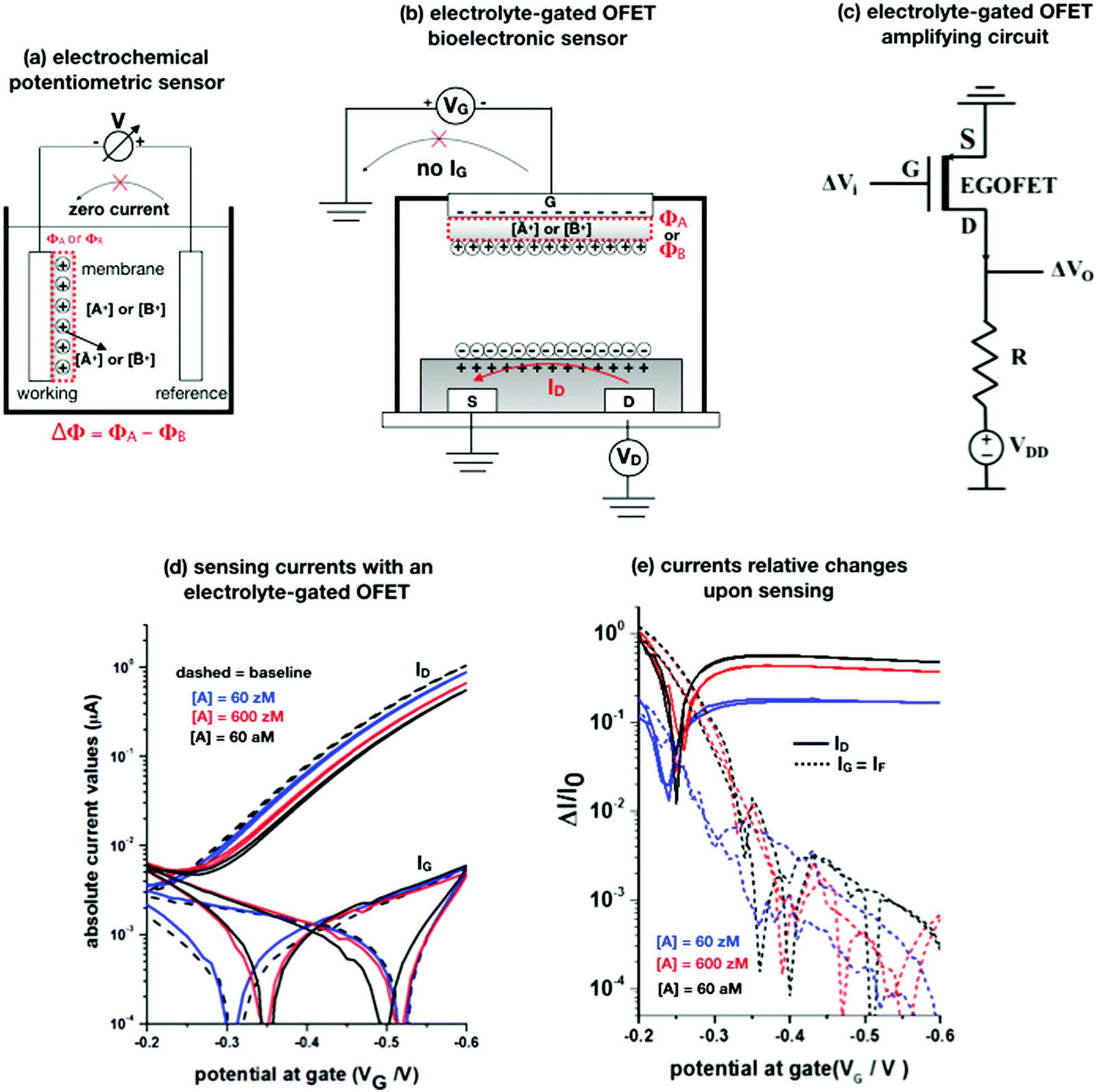 | ||
Fig. 2 (a) A schematic of an electrochemical potentiometric sensor comprising the working and the reference electrodes. The working electrode is covered by an ion-selective membrane that can selectively up-take the analyte A+ whose concentration in the electrolyte is [A+]. A species B+, that is not up-taken by the membrane, serves in a negative control experiment. At the equilibrium a partitioning of the species between the electrolyte and the membrane occurs, leading to [Ā+] and [![[B with combining macron]](https://www.rsc.org/images/entities/char_0042_0304.gif) +] retained concentrations, respectively. (b) The typical structure of an electrolyte-gated field-effect transistor sensor comprising a selective membrane attached to the gate that is capacitively-coupled via an electrolyte to an organic p-type semiconductor connected via a source (S) and a drain (D) electrode. (c) A simple p-type EGOFET based voltage-amplifying circuit comprising the FET and a loading resistance R. (d) EGOFET transfer-characteristics encompassing both ID and IG absolute values current vs. VG at VD = −0.4 V, measured in the forward and reverse mode. Poly(3-hexylthiophene-2,5-diyl) serves as the organic semiconductor while all the electrodes are made out of gold. The analyte A is the immunoglobulin-M while the gate is biofunctionalized with 1012 cm−2 anti-immunoglobulin-M antibodies that are specific for the analyte. The base-line (black dashed-line) is measured on the bio-functionalized gate incubated in a phosphate-buffer–saline solution. Afterwards, the same gate is exposed, in sequence, to the following standard-solutions of Immunoglobulin-M at concentrations of: 60 zM (blue-curve), 600 zM (red-curve) and 6 × 10⁶ zM (black). (e) The same data of panel (d) are plotted as the relative changes of the ID and IG currents measured in the presence of the analyte (I) with respect to the baseline (I0). The plotted response is ΔI/I0 = (|I − I0|/I0). More details can be found in ref. 51. +] retained concentrations, respectively. (b) The typical structure of an electrolyte-gated field-effect transistor sensor comprising a selective membrane attached to the gate that is capacitively-coupled via an electrolyte to an organic p-type semiconductor connected via a source (S) and a drain (D) electrode. (c) A simple p-type EGOFET based voltage-amplifying circuit comprising the FET and a loading resistance R. (d) EGOFET transfer-characteristics encompassing both ID and IG absolute values current vs. VG at VD = −0.4 V, measured in the forward and reverse mode. Poly(3-hexylthiophene-2,5-diyl) serves as the organic semiconductor while all the electrodes are made out of gold. The analyte A is the immunoglobulin-M while the gate is biofunctionalized with 1012 cm−2 anti-immunoglobulin-M antibodies that are specific for the analyte. The base-line (black dashed-line) is measured on the bio-functionalized gate incubated in a phosphate-buffer–saline solution. Afterwards, the same gate is exposed, in sequence, to the following standard-solutions of Immunoglobulin-M at concentrations of: 60 zM (blue-curve), 600 zM (red-curve) and 6 × 10⁶ zM (black). (e) The same data of panel (d) are plotted as the relative changes of the ID and IG currents measured in the presence of the analyte (I) with respect to the baseline (I0). The plotted response is ΔI/I0 = (|I − I0|/I0). More details can be found in ref. 51. | ||
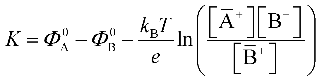
The potential measured at the working electrode under the ideal conditions of the Total-Equilibrium Models and the assumption that the phase-boundary electrochemical potential (or Fermi level) at the electrode–membrane/electrolyte governs the response32 is:  with kB being the Boltzmann constant, T the temperature, e the elementary charge, z = +1 the charge of the ion A+ and aA and āA the A ion activities in solution and in the membrane, respectively. Φ0A is a constant that accounts for the contribution of the standard chemical potentials of A+ in the two phases. Under the assumption of working with a sufficiently diluted solution, the activities coincide with the molar concentration [A+] and [Ā+] so that
  . If a reference species B+, of known concentration [B+], that does not selectively interact with the membrane, serves in a negative control experiment, the measured potential shift is:
  . This is the measured zero potential shift and enables the quantification of the average and the standard deviation of the noise of the sensor response. The analytical signal for the overall electrochemical potential shift ΔΦ = ΦA − ΦB is, hence, quantitatively related to the analyte concentration [A+] by the Nernstian-like equation:
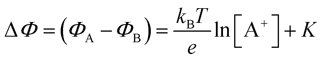 | (1) |
 . Importantly, the Nernstian quantitative correlation between ΔΦ and [A+] only holds under the stringent conditions that no ionic or electronic current flows in the cell when ΔΦ is measured. For such an electrochemical potentiometric sensor, the analytical sensitivity, taken as the slope of the calibration curve,24 ΔΦ = ΦA − ΦBvs. [A+] with ΦA measured against standard concentration solutions of A+, is given by:
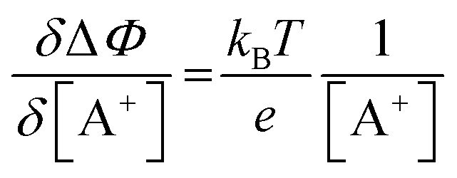 | (2) |
A potentiometric sensor is generally used to detect charged analytes. However, just as an example, potentiometric sensors based on Molecularly Imprinted Polymer membranes have been successfully developed to sense organic compounds in their ionic and neutral forms.33,38 Indeed, these membranes, have gained wide acceptance as new artificial recognition elements exhibiting affinity and selectivity comparable to those of natural recognition elements such as antibodies and enzymes.39–41 These evidences show that a membrane of a potentiometric sensor can be designed to selectively detect not only an ionic species but also analytes such as antigens or DNA strands, that can or cannot bear a net charge. To this end, antibodies or complementary DNA strands can be stably embedded or even covalently attached to a substrate forming the membrane of recognition elements. At the equilibrium, governed by the Donnan equations,42 the selective biochemical reactions leading to the formation of complexes between the biological recognition elements and the analytes, can lead to a net charge displacement or rearrangement of charges (dipoles) within the membrane, eventually shifting its electrochemical potential by ΔΦ. This shift can be measured, with higher sensitivity (vide infra) also with FET-based potentiometric detection. Indeed, EGOFETs have been proven capable of detecting neutral species such as odorant molecules in a capacity coupled configuration.15 For this reason, in the following we will consider a generic analyte A without explicitly referring to its charge.
The electrolyte-gated field-effect transistors
The origin of the electrolyte-gated field-effect transistors can be traced back to the early days of the transistor43 when Brattain and Garrett reported on a study of the properties of the interface formed by a semiconductor (germanium) and an electrolyte. Important seminal work on this topic was carried out afterwards by Gerischer and co-workers.44 These works generated key knowledge bridging the worlds of device physics and electrochemistry, which is essential to the understanding of FET-based electrochemical sensors.In Fig. 2b a typical EGOFET comprising a membrane of recognition elements attached to the gate electrode (G), is shown. As customary for an FET, the source (S) and drain (D) electrodes are put in contact via a semiconducting layer forming, all together, the transistor channel. The distance between the source and drain electrodes is the channel length L, while the width of the contacts defines the channel width W. Here, we mostly refer to organic semiconductors as channel materials but the conclusions are general and can be applied to any electronic material that is stable under a bias in an electrolyte. The main peculiarity of an EGOFET consists in engaging an electronic insulating and ionic conducting electrolyte acting as the dielectric that couples the gate electrode G with the channel. In the featured case, the latter is covered by the membrane but an equivalent behaviour can be seen if the membrane is attached to the semiconductor surface.4
Before entering into the sensing mechanisms, the EGOFET operation in the electrolyte is described. Upon application of a VG bias (with the respect to the grounded source) the gate modulates, according to its electrochemical potential, the conduction in the EGOFET semiconductor. This occurs by means of the CDL, which has a large capacitance CCDL of about 1–10 μF cm−2, forming at the gate–membrane/electrolyte interface. A second CDL eventually establishes at the electrolyte/semiconductor interfaces that capacitively couples to the gate/electrolyte one. The CDLs are built via transient ionic-currents (non-faradaic) measured as an IG gate-leakage ionic-current that extinguishes once the electrostatic equilibrium is reached. Relevantly, no electronic-faradaic current should flow either; hence the operational gating potentials should span across ranges where all the materials involved in the device (semiconductor, electrodes, membrane biological recognition elements, etc.) are redox inert. The charges accumulated in the semiconductor give rise to the output ID current that flows from source to drain, under a VD bias. At this stage when there is no IG current flow between the gate and the source/drain electrodes, ID can be measured. Under these conditions the zero-current (IG = 0) equilibrium potential governing a Nernstian behaviour is satisfied. Indeed, under the gradual channel approximation45 the electric field along the channel, generated by VD, is much lower than that perpendicular to the channel, generated by VG. Hence, ID is perturbating the equilibrium, only negligibly. EGOFETs can hence be considered to be potentiometric sensors, where the capacitive-coupling between the gate/membrane and the semiconductor channel transduces the gate/membrane electrochemical potential shift by modulating the ID current.
As in any FET, ID is measured by applying a VD bias at the drain with respect to the grounded source and the analytical expressions for a p-type EGOFET in the linear (IlinD) and the saturated (IsatD) regions of the output characteristics are:45
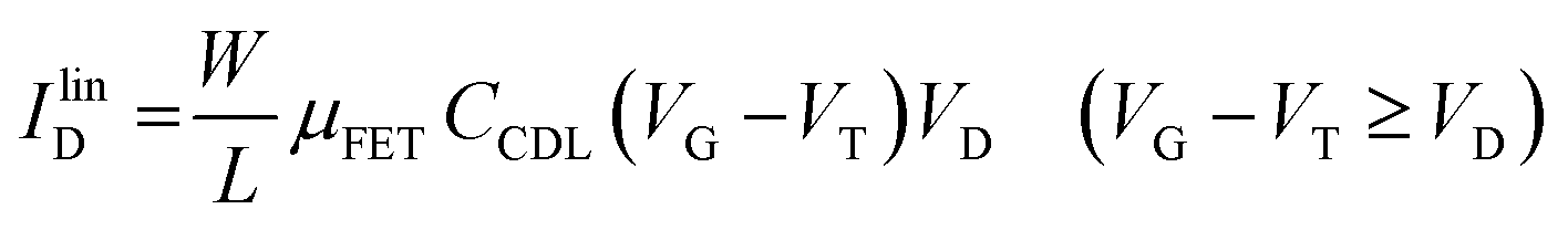 | (3a) |
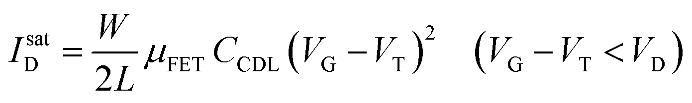 | (3b) |
The EGOFET base-line is acquired by measuring the IDvs. VG current at a fixed VD (transfer-characteristic curve) when the pristine membrane covers the gate. The sensing that encompasses three steps, is performed afterward. In step one the gate covered with the selective membrane is allowed to interact with the analyte A while immersed in a solution of concentration [A]; eventually the membrane retains a concentration [Ā] and its electrochemical potential sets at ΦA. This is measured as a shift of VT as compared to the value extracted from the base-line. In step two a duplicate of the same gate/membrane electrode, serving in a negative control experiment, is exposed to a solution of B (reference species of known concentration not interacting with the selective membrane) so that a fixed and negligible concentration [] is retained and the potential stably sets at ΦB which enables the measurement of the ID base-line (I0). This sets the level of the measured zero level with its associated error. As an instance, if A is an antigen whose cognate antibody is embedded in the membrane, B would be another protein acting as an interferent that does not selectively interact with the embedded antibody. Once the equilibrium in either the gates is reached, the EGOFET transduction of ΔΦ starts. This is the third step accomplished with the two gates positioned, alternatively, on top of the transistor channel as depicted in Fig. 2b. Upon application of the VG bias the gates modulate, according to their ΦA or ΦB electrochemical potential, the ID current. When the EGOFET is operated at fixed VD and VG the ID variation in the linear and saturation region upon a ΔΦ shift of VT, are given by the following equations:
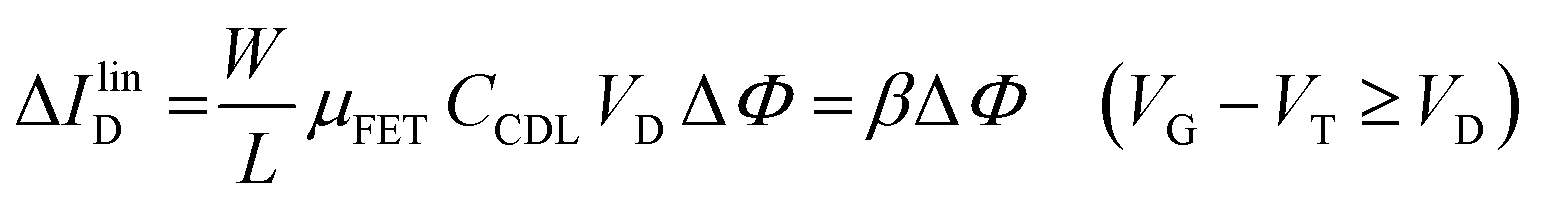 | (4a) |
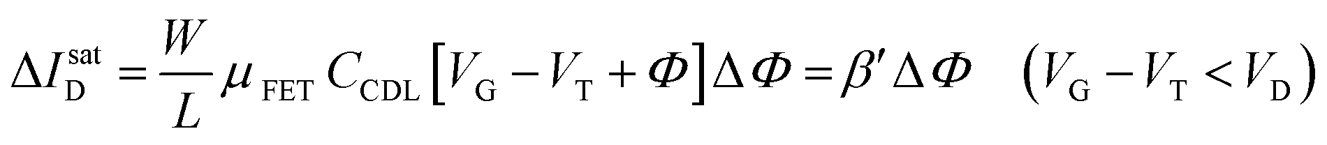 | (4b) |
Eqn (4) shows that the change in the EGOFET output current, ΔID, upon sensing is proportional to the ΔΦ output of a homologous potentiometric electrochemical sensor response (eqn (1)) through a coefficient β or β′ corresponding to the EGOFET transconductance 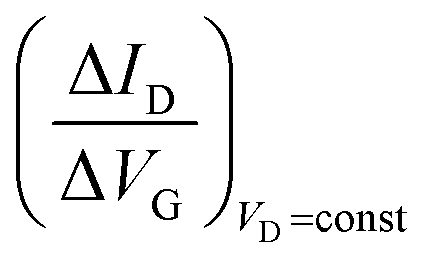 . Considering an EGOFET with W/L = 102, CCDL = 1 μF cm−2, μFET = 10−2 cm2 V−1 s−1, which is operated at VG = VD = 1 V, it results that β′ ≈ β ≈ 1 μS. Indeed, an FET works as a voltage amplifier when its output current is converted into an output voltage by means of a load resistance R. One of the simpler amplifying circuits that can be devised to operate a p-type FET as a voltage amplifier is shown in Fig. 2c. In this circuit configuration the source is connected to ground, a suitable input voltage Vi is applied to the gate and a resistor is connected between the drain and the supply voltage VDD (VDD < 0 V). The output voltage is taken at the drain electrode of the p-type FET. Upon sensing, the circuit input bias shift is ΔVi = ΔΦ, which results in a variation of the output voltage ΔVO = −ΔID·R where ΔID is the current variation upon sensing ΔΦ given by eqn (4). In order to maximize the voltage amplification, the EGOFET is operated in the saturation regime (eqn (4b) holds) and hence the variation of the output voltage VO with respect to the input variation
 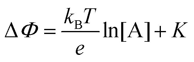 (eqn (1)) due to sensing results:
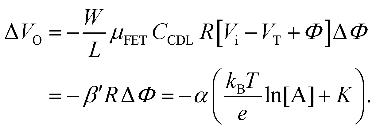 | (5) |
 | (6) |
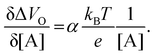
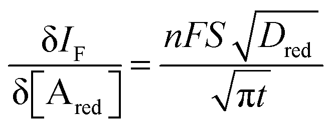
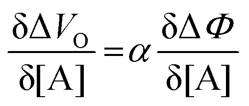 and it becomes apparent that the EGOFET sensitivity can be up to a = 103 times larger than that of a homologous electrochemical potentiometric sensor. Indeed, a steeper calibration curve returns a larger response signal at a given analyte concentration therefore, lower limits-of-detection (LODs)4,24 are to be expected for EGOFET sensors compared to homologous potentiometric electrochemical ones exhibiting the same signal-to-noise average level and standard deviation.
It is indeed a fact that EGOFETs have been demonstrated to be among the highest performing label-free biosensors. They have been proven to reach LODs in the 10−18 M (aM) range46–48 exhibiting also a logarithmic Nernstian dependence on the analyte concentration. Moreover, very recently, the single-molecule with a large transistor (SiMoT) technology, has been proven capable of detecting biomolecules down to the physical-limit reaching LODs of 10−21 M (zM).49–53 These ultimate sensitivities have been explained by invoking two amplification effects: a collective domino effect associated with a hydrogen-bonding network and an optimized capacitive coupling4,51 Here we will address only the latter. To this end, an example of SiMoT potentiometric EGOFET output curves is given in Fig. 2d; these are transfer-characteristics (ID or IGvs. VG at VD = −0.4 V) for a p-type EGOFET integrating a membrane comprising a self-assembled monolayer with trillions of anti-Immunoglobulin M (anti-IgM) antibodies. It has been demonstrated by duly evaluating the LOD level, that such a device can sense IgM (the analyte A) at 20 zM which corresponds to 1 ± 1 molecules in the 100 μl assayed sample.4,51 Relevantly, Fig. 2d shows a semi-logarithmic plot of both the source–drain, ID, and the gate leakage, IG, currents that are measured at different concentrations of A. The dashed curve is the base-line current measured before the sensing. The comparison between the ID and IG curves shows the typical features characterizing a bioelectronic device operated as a potentiometric sensor by means of a capacity-coupled detection. The first comment concerns the amplitude of these currents: while ID is in the μA range, IG is always in the low nA range at most, meaning that the ID/IG ratio at VG = −0.5 V can be as high as 103. This evidence shows that the EGOFET is operated with the IG zero-current potential condition which is a strict requirement for the Nernst equation to be used for quantification purposes in potentiometry. Fig. 2d shows also that the dependence of IDvs. [A] is logarithmic.
The second peculiar aspect concerns the dependence of the currents on the analyte concentration. This is better illustrated in Fig. 2e where the same data of Fig. 2d are given as the relative changes in ID and IG at each assayed concentration. Specifically, in Fig. 2e the current measured at each concentration (I) is subtracted of the base-line value (I0) and the absolute value of the difference is normalized for the base-line value. This is the relative current change upon sensing addressed as ΔI/I0 = (|I − I0|/I0). Such a parameter should be always considered as a sensor response as it normalizes the device to device differences as well as the differences in the geometrical factors.24 Indeed, a large fractional decrease of ID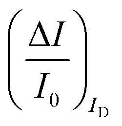 can be measured upon sensing that reaches more than 80%; conversely, very small fractional variations of IG
 are measured so that
 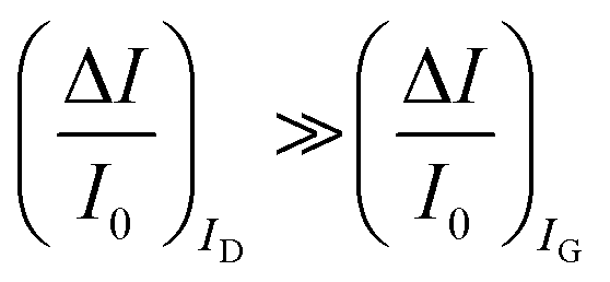 ; most relevantly no significant dependence of
 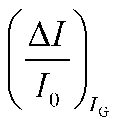 over [A] is seen. This implies that the capacitive-coupling between the sensing membrane and the resistor, demonstrated by eqn (5) to be amplified compared to a homologous electrochemical sensor, is the only sensing mechanism. Both evidences also imply that no significant electrochemical reaction is indeed involved at any stage as IG is always negligible.
Sensors involving metal-oxide-semiconductor field-effect transistor (MOSFET) transducing technology belong also to the class of potentiometric biosensors.54–56 MOSFET biosensors originate from the ion-sensitive-FETs (ISFETs) introduced in the early 1970s.57 The most successful application of ISFETs is still as pH sensors but they can also be used to indirectly detect biochemical reactions that induce a local pH change. ISFETs offer the advantage of being fully compatible with standard complementary-MOS (CMOS) platforms allowing scalability and low-power operation as they are biased with a few volts (5 V usually). All together these features make them suitable for handheld sensing devices and lately also for single molecule array detections of genetic biomarkers.58 Relevant here is to explain what are the main differences between an MOSFET/ISFET and an EGOFET. In its simplest form a MOSFET-based biosensor comprises a dielectric layer that has been deprived of the top gate electrode. The surface of the gate dielectric covered with an ion-selective membrane or with a layer of biological recognition elements needed to selectively bind the analyte. The signal measured is the current flowing in the transistor channel that is controlled by the binding occurring at the membrane on the gate dielectric. There are two primary differences between the EGOFET and an MOSFET. The MOSFET dielectric is an inorganic layer, mostly an oxide that is both electronic and ionic insulating. The semiconductor serving as a channel material is also inorganic in nature. In contrast, an EGOFET organic bioelectronic transistor utilizes a liquid or gel electrolyte as a dielectric, which is an ionic conductor and an electronic insulator. Here the semiconducting layer is an organic material or more generally, a large-area and solution processable layer, that can be either ion-permeable or ion-impermeable.4,14 The advantage of an organic bioelectronic sensor compared to an ISFET resides in the biocompatibility and low-cost processing of the materials involved, and their flexibility and conformability that make the devices also amenable to direct interfacing with organs such as the brain for neuromorphic applications.59 However the most relevant advantage of organic bioelectronics over MOSFET sensing technology relies on the different capacitances engaged. Indeed, the capacitance of the electrolyte gating medium used in an EGOFET is in the μF cm−2 range, while that of an MOSFET inorganic dielectric is typically of the order of nF cm−2. This enables a bioelectronic transistor to be operated in the sub-volt regime14 hence they are less-power consuming than an MOSFET sensor. More importantly, as it has been addressed in previous publications,4,5,15 it makes it possible to establish in organic bioelectronic sensors an optimal capacity coupling between the high capacitance associated with the ion/water-permeable membrane of biological recognition elements and the transducing electronic channel. In fact, the capacitance of the membrane and that of the channel material are in series and therefore the smaller one dominates. When the low capacitance of the dielectric in an MOSFET is in series with the high capacitance of the membrane attached to it, the former will dominate. This means that the effect of the changes occurring in the membrane upon sensing can be shadowed by the low capacitance of the dielectric which does not change upon sensing. This holds particularly true if weak charge/dipole rearrangements are associated with the binding process. Conversely in an EGOFET the two capacitances are comparable and hence a good coupling can be established between the membrane and the channel and the binding of the analyte to the membrane can be very sensitively detected. Indeed, small dielectric changes can be tackled with an EGOFET that is capacity modulated.15
Electrochemical amperometric sensors
The other main class of electrochemical biosensors are the amperometric ones,30,60 that have been also proven capable of single enzyme detection.61 The essential conceptual structure comprises two electrodes (working and reference) immersed in an electrolyte encompassing an analyte A which is electroactive or redox in this case. This means that A can undergo an oxidation (give away an electron to the electrode) or a reduction (accept an electron from the electrode), the electrolysis reactions being: Ared–e− → Aox and Aox + e− → Ared. Amperometric and voltammetric techniques involve the application of a potential between the working and the reference electrodes while the current resulting from the electrolysis of the analyte is measured. This current is faradaic, IF, as it serves to establish the equilibrium at the electrode/electrolyte interface via the transfer of electrons. While potentiometric measurements are carried out at the equilibrium as no current flows, amperometric measurements are carried out in a system that is, by definition, out of equilibrium. To make sure that the amperometric measurement is carried out under reproducible conditions, it is necessary to have full control on the applied potential. In a voltammetry the external potential is scanned over a given potential range while in amperometry the external potential is fixed. In both cases the control over the external potential applied is achieved by the use of a reference electrode such as the Ag/AgCl one.In the presence of the redox species A, the working electrode electrochemical potential is given by the following Nernstian-like equation: 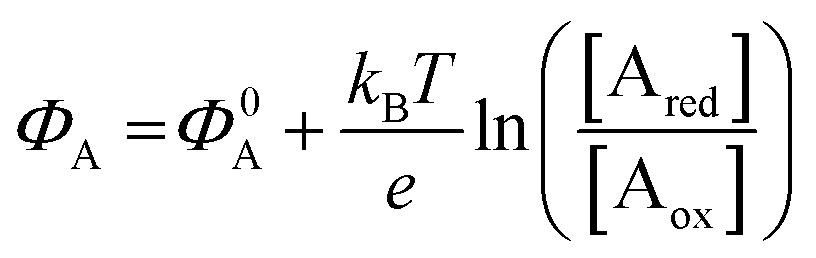 with [Ared] and [Aox] being the concentrations of A in its reduced and oxidised forms, respectively. Φ0A is the standard electrochemical potential of A, namely the potential measured under standard conditions and at the equilibrium when [Ared] = [Aox] and hence no faradaic current flows.26 The Faradaic current IF that flows to bring the system to equilibrium and the relevant potential shift ΔΦ = ΦA − Φ0A can be both measured, in amperometric or potentiometric configurations respectively, as they are both stoichiometrically connected with the concentration of the species to be detected that is either in its reduced or oxidized form.
The analytical expression of the faradaic current IF is related to the rate of the oxidation and reduction reactions and, assuming an exponential dependency of the rate constants on the electrode potential V, the faradaic current is analytically reproduced by the Butler–Volmer equation:26
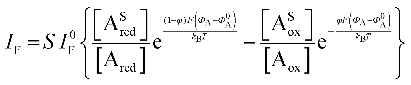 | (7) |
 | (8) |
 | (9) |
As anticipated, a redox species can be quantitatively detected also via potentiometry by measuring the shift of the working electrode electrochemical potential ΔΦ = ΦA − Φ0A ruled the Nernstian equation: 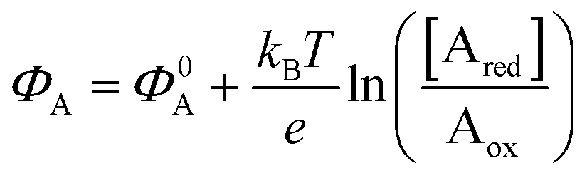 . Indeed, in this case the rule of the “zero-current” flowing during the potentiometric measurement (IF = 0) is to be complied with.
A schematic for the amperometric electrochemical sensor featured for this review is given in Fig. 3a. Here the working electrode comprises a gold lamina covered by a poly(3,4-ethylenedioxythiophene) polystyrene sulfonate (PEDOT:PSS) film. This configuration has been chosen to enable a fearer comparison between the amperometric sensor and the OECT (see next section) sensor discussed in this review. Since the electrochemical potential (Fermi level) of the gold and the pristine p-doped PEDOT:PSS are almost resonant and the latter is also highly conductive, no additional potential drop is associated with the PEDOT:PSS layer as compared to a sole gold electrode.4 This is proven by the cyclic voltammetry of the ferrocyanide redox couple oxidation and subsequent reduction given in Fig. 3b as a red solid-line that is compared to the voltammetric trace of the PEDOT:PSS film in the bare electrolyte (baseline, dashed black-line). This experiment shows that the p-type doped pristine PEDOT:PSS is highly conductive and has the same electrochemical potential of Au as the ferrocyanide electrochemical potential (not shown), taken as the half-sum of the oxidation and reduction peaks, which does not significantly shift when measured on bare gold and on Au/PEDOT:PSS.4
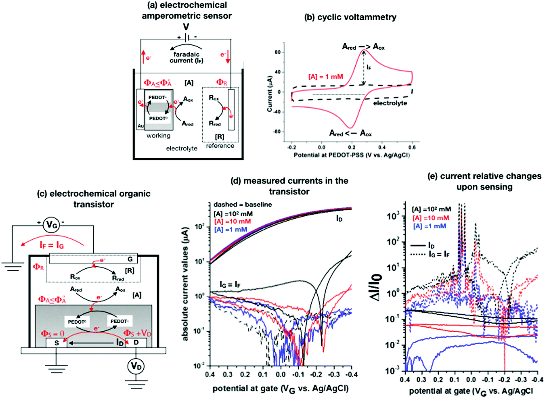 | ||
| Fig. 3 (a) Simplified electrochemical amperometric two-electrode cell for the detection of the redox species Ared undergoing an oxidation process. In the featured case, the working electrode is a gold layer covered by a PEDOT:PSS film while the other is the reference electrode. (b) A cyclic voltammetry experiment is shown that is measured in a standard three-electrode cell comprising an Au/PEDOT:PSS working electrode, an Au counter electrode as well as an Ag/AgCl (KCl sat.) reference electrode. The PEDOT:PSS is spin coated from a solution comprising an aqueous dispersion of PEDOT:PSS added with dimethyl sulfoxide and annealed afterwards. The cyclic voltammetry was carried out in a potassium chloride electrolyte and in the presence of 1 mM potassium ferrocyanide K4[Fe(CN)6] at a scan rate of 0.1 V s−1. The anodic current was set positive. All the experimental details can be found in ref. 4. (c) An organic electrochemical transistor comprising a reference electrode as a gate and PEDOT:PSS as a semiconducting film is used to detect the A electroactive species undergoing the same oxidation process as in Fig. 3a. (d) The absolute values of the ID and IG currents of an OECT, measured in the bare electrolyte which is in 0.1 M KCl (dotted black-curve) and in the presence also of 1 mM (solid blue-curve), 10 mM (solid red-curve) and 100 mM (solid back-curve) potassium ferrocyanide K4[Fe(CN)6], are shown as measured at VD = −0.4 V. The experimental details, that can be found in ref. 4, are here briefly recalled. The OECT is composed of gold source/drain parallel contacts defined on a glass substrate and the PEDOT:PSS film is deposited as in the electrochemical amperometric working electrode. The device parameters are the following: channel length L = 10 μm or 20 μm, channel width W = 100 μm, capacity per unit area CCDL = 4 × 10³ μF cm−2. A cell was glued around the channel area and was filled with the electrolyte alone or added with the K4[Fe(CN)6]. An Ag/AgCl (KCl sat.) served as a gate electrode. A maximum transconductance of 1.5 mS V−1 is estimated from the transfer characteristics curve in the electrolyte. (e) The same data of panel (d) are plotted as the relative change of the ID and IG currents measured in the presence of the analyte (I) with respect to the baseline (I0). The response is plotted as ΔI/I0 = (|I − I0|/I0). | ||
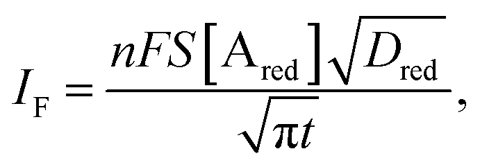
The A redox species to be detected is here assumed to be in its reduced form (Ared). When V is switched on, the electrochemical potential of the working electrode ΦA can be set resonant or lower than the standard potential of A species, Φ0A. An electron can hence be transferred from Ared to the working electrode, with Ared turning into its oxidized form Aox. In this electron-transfer process, the PEDOT:PSS layer, acting as mediator, shuttles the electrons from the solution to the Au electrode. The reaction can continue also if ΦA ≤ Φ0A but it slows down until it stops when ΦA > Φ0A. Indeed, when ΦA > Φ0A a potential barrier at the interface blocks the electron flux from A in solution to the electrode. Conversely, at ΦA = Φ0A the electrons can move back and forth from the electrode to the solution and a zero-net-current flows (IF = 0) as the reaction reaches the equilibrium. If ΦA < Φ0A the oxidation process can continue until all the analyte molecules have undergone a redox conversion into their oxidation form. The faradaic current measured in this condition (in fact the diffusion limited one) is quantitatively correlated with the analyte concentration according to the Cottrell eqn (8). The electronic faradaic current flow starts when ΦA ≤ Φ0A and it would be transient if not sustained by an opposite redox reaction that takes place at the other electrode. Here a species R takes the electron released by A, turning from its oxidized (Rox) to its reduced (Rred) state. However, such a setting would not suffice to assure the potential in the electrolyte to stay fixed at ΦA ≤ Φ0A which is essential to enable the complete (quantitative) oxidation of Ared. Indeed, due to the resistances in the solution and in the electrodes, the actual potential in the electrolyte would be dependent on the magnitude of the faradaic current that is flowing. To overcome this issue, a reference electrode (such as an Ag/AgCl one) with its potential fixed at ΦR is used. In contrast, since in an electrochemical potentiometric measurement no current flows, the need for an ideally non-polarizable reference electrode is less stringent.
When a fixed potential V + ΦR = ΦA ≤ Φ0A is applied, according to the Butler Volmer eqn (7), the current has a peak when the voltage is applied and then decreases indirectly proportional to the square root of the time, as predicted by the Cottrell eqn (8). The reason for this behaviour is that the initial electrode reaction, Ared–e− → Aox creates a concentration gradient, which in turn creates a continuing flux of the reductant (Ared) to the electrode. Such a flux causes a depletion zone of the reductant, where thickness increases with time. The thickness of the depletion layer l can be estimated by the relation 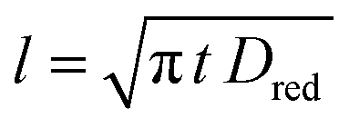 .
.
The organic electrochemical transistors
The other organic bioelectronic sensors discussed here are the OECTs. Notably, they have been largely the preferred structure for organic bioelectronic sensing.62–66 A Web-of-Science search returns in fact at least twice as many papers published on electrochemical transistor sensors as for electrolyte-gated sensors.An OECT is structurally like an EGOFET as it comprises a channel, with its semiconducting layer across the source and drain contacts as well as a gate, all immersed in an electrolyte (Fig. 3c). The difference between the two structures is in the nature of the CDLs that are formed. EGOFETs engaging ion-impermeable channel materials such as graphene or poly(3-hexylthiophene-2,5-diyl), P3HT films that are both hydrophobic, form in an aqueous electrolyte, two-dimensional CDLs. Conversely, OECTs encompass ion-permeable organic materials known as mixed ionic/electronic conductors.67 The prototypical example is a PEDOT:PSS film, which is porous and hydrophilic enabling ions in aqueous solutions to enter into the bulk forming a very large three-dimensional capacitance.68,69 Relevantly, a given organic material can serve both as a semiconducting channel for an OECT and an EGOFET depending on the ions chosen for the electrolyte solution. As an example, poly[2,5-bis(3-tetradecylthiophen-2-yl)thieno[3,2-b]thiophene] – PBTTT is impermeable to hydroxides but is permeable to picric acid. Hence a 2D or a 3D capacitance can be imparted on the same device by just changing the ions of the electrolyte.70
OECTs like EGOFETs can be operated as potentiometric capacitive-coupled FET-devices exhibiting extremely high figures-of-merit. For instance, the study of ionic-electronic volumetric interactions leads to the design and realization of unipolar inverters with unprecedently high gain,71 while the sensing involving immunometric interactions returns LODs in the aM range.47 In this setting no conceptual difference exists between an EGOFET and an OECT, as the electrolyte is invariably an ionic-conducting and electronic-insulating medium because no electroactive species is involved. These are however exceptions as in the so far published studies, OECTs have been largely engaged for the detection of electroactive species such as metabolites. In this setting the electrolyte is indeed both ionically and electronically conductive and the OECTs have been suggested to operate either as potentiometric or amperometric sensors. Either choice is correct as long as the operational conditions are set accordingly to comply with the right constrains. Namely, in an amperometric measurement the imposed potential needs to be fixed and controlled via a reference electrode while in a potentiometric one, the zero-current equilibrium condition is to be complied with. Failing to do so, impairs the choice of the right functional dependence, Nernstian or Cottrellian, to be used and hence the quantification of the analyte can be incorrectly performed. Moreover, the rationale of the sensing mechanisms can be imprecisely defined along with the advantage of using a three-terminal electronic device over a homologous electrochemical one. This is of relevance also considering that OECTs have been shown to reach detection limits in the nM range at most which are also in the reach of redox electrochemical sensors.4
To contribute to shedding some light on these issues, the OECT operational regimes to detect the faradaic current IF generated by the same redox species A measured in the experiment of Fig. 3a, are discussed. Before presenting the experimental data gathered, an OECT amperometric detection of A is schematically shown in Fig. 3c. For the sake of comparison with the amperometric electrochemical sensor given in Fig. 3a, the OECT is designed with the reference electrode serving as the gate while the PEDOT:PSS channel acts as an homolog of the working electrode of Fig. 3a; also in the case of the OECT, the oxidation of Ared occurs at the PEDOT:PSS interface. In contrast, according to several published papers, the A electrochemical reaction could take place at the gate, but in this case, it is not clear where the necessary reference electrode should be placed.
When an appropriate negative VG bias is applied, the R species reduces, a faradaic current IF flows out of the gate and it is measured as the gate leakage current IG. This generates a potential ΦA + ΦS = VG + ΦR ≤ Φ0A at the PEDOT:PSS/electrolyte interface that, as the source is grounded becomes ΦA = VG + ΦR ≤ Φ0A. In a similar manner, for the drain electrode, the potential at the PEDOT:PSS interface is: ΦA + VD = VG + ΦR ≤ Φ0A. Part of the oxidation faradaic current should hence flow also from this electrode as VD is negative and the condition ΦA ≤ Φ0A holds here as well. Also in the OECT the electrochemical potential of the pristine p-doped PEDOT:PSS is resonant with ΦA ≤ Φ0A. Hence, this layer enables the IF = IG current to flow into the source and drain electrodes.72 The ID current intensity depends on the PEDOT:PSS conducting state which is affected by the IG flow. The analytical mathematical functional dependence of ID on IG, ID = f(IG), is however still missing which does not enable a rigorous quantification of the analyte. Under these conditions it is not well-defined whether an amplification factor is introduced by an OECT as compared to the amperometric electrochemical sensor and what is the phenomenon supporting it. To this end, the transport in PEDOT-PSS can be described as the result of the interplay between two electrochemical potentials: the electronic, Φe, associated with the amorphous blend of the conjugated polymer (PEDOT) and the ionic, Φi, describing the ensemble of the negative and fixed charges of the polyelectrolyte (PSS). In fact, while no charge transfer between the two systems can occur, the driving towards the electrostatic equilibrium where Φe = Φi, brings the PEDOT in its p-doped state. An electron or an ion injection can lead also, via capacitive coupling, to a shift of the two electrochemical levels. This is the rationale according to which ID should be a function, yet to be derived, of IG and eventually of the concentration of the redox species to be detected viaeqn (8).
To experimentally measure if an amplification is in place the experiment shown in Fig. 3d is proposed. Here an OECT homolog of the electrochemical cell used for the experiment in Fig. 3a, is used to measure both the ID and the IG = IF currents vs. VG at VD = −0.4 V flowing in the device in the bare electrolyte (dashed black-line) and when the ferrocyanide redox couple is added at a concentration of 1 mM (solid blue-line), 10 mM (solid red-line) and 100 mM (solid black-line). Relevantly, the maximum transconductance measured for the PEDOT:PSS OECT in the bare electrolyte (KCl only) is equal to 1.5 mS V−1, which is in agreement with state-of-the-art.71 The data shown in Fig. 3d illustrates two main features: the ID curves are larger than the IG ones and, while only barely visible in logarithmic scale, ΔID > ΔIG. However, while they both scales with the analyte concentration, the IG curves show a much more pronounced dependence. To better highlight this latter feature, in Fig. 3e the relative changes of these currents are plotted. Also, in this case, the current measured at each concentration (I) is subtracted of the base-line value (I0) and the absolute value of the difference is normalized for the base-line value. This is the current relative change upon sensing addressed as ΔI/I0 = (|I − I0|/I0). The fractional change of a sensor output in this case offsets the geometrical differences affecting the current flowing between source and drain (ID) and that flowing between the gate and the other two electrodes (IG = IF). The solid curves stand for the  differential currents while the dashed are relevant to the
  . As it is apparent, both the ID and IG fractional changes show a dependence from the analyte concentration but the OECT amperometric response to ferrocyanide measured with the IG = IF current is much larger than that measured with ID so that
  in the case of an OECT detecting a faradaic current. Hence, at least in this setting, considering that IG is the current measured in an amperometric electrochemical homologous sensor, the occurrence of an improvement of the sensor response fractional change with an OECT, seems not to be in place.
In an amperometric electrochemical detection the signal to be amplified is the faradaic current IF, hence, the transistor structure to be designed should be that of a current-amplifier rather than a capacitive coupled voltage-amplifier. To this end, the conceptual structure depicted in Fig. 4 is suggested. This is a bipolar-junction-transistor characterized by three regions, known as emitter, base, and collector, alternatively p- or n-doped. A p-doping endows a semiconductor with a number of positive-charge carriers that is larger than the negative-charge ones. The positive-charge carriers are hence addressed as majoritarian, while the latter are minoritarian carriers. The opposite holds for an n-type doped material. In the featured case, two p–n and n–p junctions are considered. The p–n junction (emitter-base) is directly-polarized as the p-type end is connected with the positive pole of a voltage supply VEE. The n–p junction (base-collector) is inversely-polarized by a voltage supply VCC. When a p–n junction is directly polarized the majority carriers flow through; when it is inversely polarized the minority ones flow. This is the rationale for a diode to act as a current rectifier. In a bipolar-junction-transistor featured in Fig. 4 the emitter is heavily p-doped while the base is lightly n-doped. When the hole majority carriers enter the base from the emitter (forward biased junction), they sink the few majoritarian electrons present in the base. Since the base is a very thin layer, most of the holes are found at the base-collector junction which is reverse biased so that they reach the collector rather than moving towards the base terminal. Under these conditions it can be demonstrated that the collector current IC (equivalent of ID) can be up to γ = 102 larger than the base one IB (equivalent of IG).
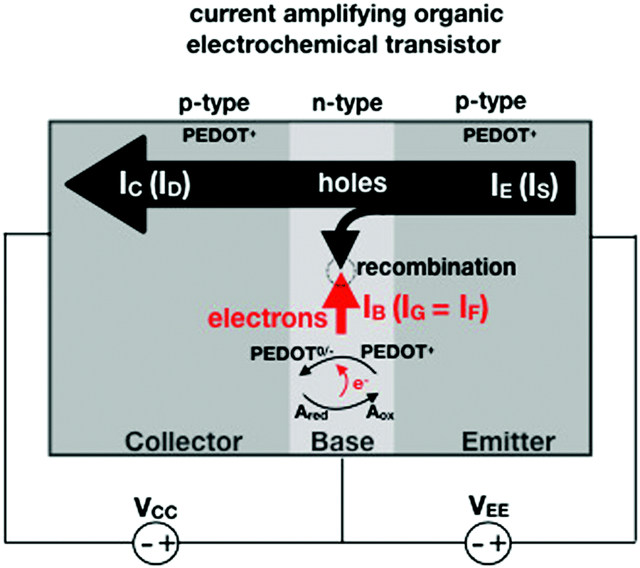 | ||
| Fig. 4 Conceptual structure of a bipolar-junction-transistor based on a PEDOT:PSS OECT serving as an amperometric sensor to detect and amplify the faradaic current generated by the species A undergoing an oxidation process in the base region. | ||
Interestingly, a PEDOT:PSS based current-amplifying device has been proposed73 and, like many other conducting polymers, can be both p-type or n-type doped. At the same time there is a very lively activity on ionotronic devices based on conducting polymers and mixed ionic/electronic conductors.74,75 It is hence conceivable to design a PEDOT:PSS based current-amplifying OECT for the amplification of the faradaic current generated by the redox reaction of A. In Fig. 4 a conceptual structure for such a device is proposed that could integrate or interface the A redox species to the base of the bipolar-junction-OECT. IF will hence be produced or injected in the base serving as the current IB and, under properly set conditions that are under study, the output current IC would be equal to γIB. If the Cottrellian conditions are satisfied IC would become:
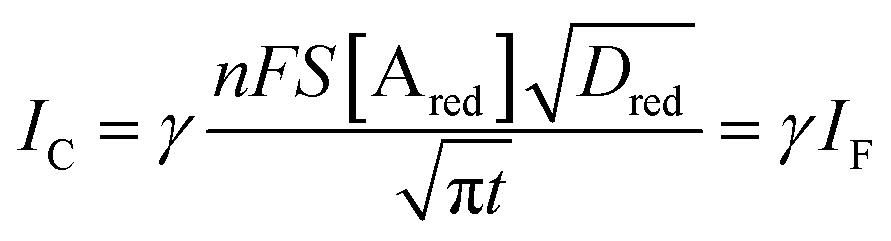 | (10) |
 becomes γ-times larger than that of eqn (9) holding for a homologous electrochemical amperometric sensor.
Last but not least, as anticipated a FET-potentiometric detection of a redox reaction can be considered. The way to proceed, could be as follows: the redox reaction is allowed to take place at the gate of the transistor while it operates as the working electrode in the cell of Fig. 3a, under the Cottrellian constraints, namely with a fixed external potential that it is V + ΦR = ΦA ≤ Φ0A. This generates a shift in the gate electrochemical potential that, at the equilibrium, can be detected via a capacitive-coupling expecting an amplified Nernstian output as per eqn (5). For the sake of completeness, it should be added that an extremely sensitive electrochemical potentiometric detection of a redox species has been recently published. Here an open circuit potential detection of single metal nanoparticle collisions was achieved, demonstrating how sensitive even electrochemical potentiometric detections can be.76,77
Concluding remarks
A systematic comparison between the electrochemical potentiometric or amperometric sensors and their transistor equivalents exhibiting clearly identified amplification factors, is presented. To this end, both the electrolyte-gated organic field-effect transistor and the electrochemical organic transistor configurations are reviewed according to a unified rational view. It is concluded that EGOFETs and OECTs operated as capacity-coupled voltage-amplifying devices can exhibit an amplification of a factor as high as 103 over homologous potentiometric electrochemical sensors when detecting ions or antigens in immunometric detections. DNA/PNA detections are possible as well. A Nernstian logarithm dependence of the sensor output with the analyte concentration, grants the correct quantification of the analyte too. Conversely, when an OECT is operated as an amperometric device to detect redox species such as metabolites, it is not clear what the mathematical analytical expression for the amplification factor is and so a general expression is lacking. It is however experimentally demonstrated that, while the absolute current change upon sensing sets ΔID > ΔIG, the more often used sensor response defined as the relative change of the signal sets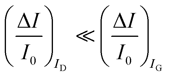 . In this case, two alternative amplifying transistor structures that can outperform a homologous amperometric electrochemical sensor, are proposed. One involves a conceptually conceived current-amplifying OECT that should exhibit a Cottrellian dependence of the transistor current output with the analyte concentration, the other involves a correctly devised potentiometric detection of a redox reaction exhibiting a Nernstian dependence of the output with the concentration.
This paper provides hence a unified rational description of a transistor amplified detection for different biochemical reactions that should guide the community in the design of organic bioelectronic structures that are truly capable of outperforming the state-of-the-art of biosensing still dominated by the highly performing electrochemical homologs.
Statement of authors contributions
E. Macchia and D. Blasi contributed to the design of the EGOFET sensors and fabricated them along with C. Di Franco. K. Manoli, D. Blasi, R. A. Picca, and E. Macchia designed the bio-functionalization of the gates and performed the bio-functionalization. E. Macchia and D. Blasi contributed to the design of the EGOFET sensing measurements and performed them. F. Torricelli designed and fabricated the OECT devices, while R. A. Picca and K. Manoli contributed to the design of the OECT sensing experiments and performed them. F. Torricelli, G. Scamarcio and R. Österbacka contributed to the design the transistors’ device structures. F. Torricelli contributed to the definition of the amplification effects and designed the amplifying EGOFET circuit. N. Ditaranto, N. Cioffi and L. Sarcina designed the electrochemical measurements and L. Sarcina performed the measurements. L. Torsi conceived and wrote the manuscript that was discussed and approved by all the authors.Conflicts of interest
There are no conflicts to declare.Acknowledgements
We are thankful to Prof. Daniel Simon and Prof. Francesco Giordano for useful discussions on the junction-bipolar-OECT functional mechanism. The following grants are acknowledged for partial financial support: Future in Research – FLOW: Dispositivi EGOFET flessibili a bassa tensione per la sicurezza in campo alimentare (ML5BJ85); Future In Research – BEND: Biosensori elettronici intelligenti per la diagnosi precoce di malattie neurodegenerative (B164PG8); H2020 – Electronic Smart Systems – SiMBiT: Single molecule bio-electronic smart system array for clinical testing (Grant agreement ID: 824946); MIUR PON – e-DESIGN: Combination of Design, Electronics and Multifunctional Materials for New Aesthetic Components (ARS01_01158); PRIN 2017 project (grant number 2017RHX2E4) “At the forefront of Analytical ChemisTry: disrUptive detection technoLogies to improve food safety – ACTUaL”. CSGI is also acknowledged for partial financial support.Notes and references
- M. Berggren, X. Crispin, S. Fabiano, M. P. Jonsson, D. T. Simon, E. Stavrinidou, K. Tybrandt and I. Zozoulenko, Adv. Mater., 2019, 31, 1805813 CrossRef PubMed.
- S. H. Wang, J. Y. Oh, J. Xu, H. Tran and Z. Bao, Acc. Chem. Res., 2018, 51, 1033 CrossRef CAS PubMed.
- D. T. Simon, E. O. Gabrielsson, K. Tybrandt and M. Berggren, Chem. Rev., 2016, 116, 13009 CrossRef CAS PubMed.
- M. R. Picca, K. Manoli, E. Macchia, L. Sarcina, C. Di Franco, N. Cioffi, D. Blasi, R. Österbacka, F. Torricelli, G. Scamarcio and L. Torsi, Adv. Funct. Mater., 2019, 1904513 CrossRef.
- K. Manoli, M. Magliulo, M. Y. Mulla, M. Singh, L. Sabbatini, G. Palazzo and L. Torsi, Angew. Chem., Int. Ed., 2015, 54, 12562 CrossRef CAS PubMed.
- X. Strakosas, M. Bongo and R. M. Owens, J. Appl. Polym. Sci., 2015, 132, 41735 CrossRef.
- https://cordis.europa.eu/project/rcn/219066/factsheet/en .
- Z. T. Zhu, J. T. Mabeck, C. C. Zhu, N. C. Cady, C. A. Batt and G. G. Malliaras, Chem. Commun., 2004, 1556 RSC.
- H. Tang, F. Yan, P. Lin, J. Xu and H. L. W. Chan, Adv. Funct. Mater., 2011, 21, 2264 CrossRef CAS.
- P. Lin, X. Luo, I. M. Hsing and F. Yan, Adv. Mater., 2011, 23, 4035 CrossRef CAS PubMed.
- S. Casalini, F. Leonardi, T. Cramer and F. Biscarini, Org. Electron., 2013, 14, 156 CrossRef CAS.
- E. Macchia, K. Manoli, B. Holzer, C. Di Franco, M. Ghittorelli, F. Torricelli, D. Alberga, G. F. Mangiatordi, G. Palazzo, G. Scamarcio and L. Torsi, Nat. Commun., 2018, 9, 3223 CrossRef PubMed.
- L. C. Clark and C. Lyons, Ann. N. Y. Acad. Sci., 1962, 102, 29–45 CrossRef CAS PubMed.
- S. H. Kim, K. Hong, W. Xie, K. H. Lee, S. Zhang, T. P. Lodge and C. D. Frisbie, Adv. Mater., 2013, 25, 1822 CrossRef CAS PubMed.
- M. Y. Mulla, E. Tuccori, M. Magliulo, G. Lattanzi, G. Palazzo, K. Persaud and L. Torsi, Nat. Commun., 2015, 6, 6010 CrossRef CAS PubMed.
- S. Cotrone, M. Ambrico and H. Toss, et al. , Org. Electron., 2012, 13, 638–644 CrossRef CAS.
- H. S. White, G. P. Kittlesen and M. S. Wrighton, J. Am. Chem. Soc., 1984, 106, 5375 CrossRef CAS.
- P. Lin and F. Yan, Adv. Mater., 2012, 24, 34 CrossRef CAS PubMed.
- J. Rivnay, S. Inal, A. Salleo, R. M. Owens, M. Berggren and G. G. Malliaras, Nat. Rev. Mater., 2018, 3, 17086 CrossRef CAS.
- C. B. Nielsen, A. Giovannitti, D.-T. Sbircea, E. Bandiello, M. R. Niazi, D. A. Hanifi, M. Sessolo, A. Amassian, G. G. Malliaras, J. Rivnay and I. McCulloch, J. Am. Chem. Soc., 2016, 138, 10252 CrossRef CAS PubMed.
- A. Giovannitti, K. J. Thorley, C. B. Nielsen, J. Li, M. J. Donahue, G. G. Malliaras, J. Rivnay and I. McCulloch, Adv. Funct. Mater., 2018, 28, 1706325 CrossRef.
- D. Grieshaber, R. MacKenzie, J. Voros and E. Reimhult, Sensors, 2008, 8, 1400 CrossRef CAS PubMed.
- Biosensors, fundamentals and applications, ed. A. P. F. Turner, I. Karube and G. S. Wilson, Oxford University Press, Oxford, 1987 Search PubMed.
- L. Torsi, M. Magliulo, K. Manoli and G. Palazzo, Chem. Soc. Rev., 2013, 42, 8612 RSC.
- J. E. Frew and H. A. O. Hill, Anal. Chem., 1987, 59, 1091A–1098A CrossRef.
- A. J. Bard and L. R. Faulkner, Electrochemical Methods: Fundamentals and Applications, 2nd Edition, Wiley, New York, 2nd edn, 2001 Search PubMed.
- D. R. Thévenot, K. Toth, R. A. Durst and G. S. Wilson, Biosens. Bioelectron., 2001, 16, 121–131 CrossRef.
- J. Wang, Chem. Rev., 2008, 108, 814–825 CrossRef CAS PubMed.
- J. D. Newman and A. P. F. Turner, Biosens. Bioelectron., 2005, 20, 2435–2453 CrossRef CAS PubMed.
- C. Malitesta, F. Palmisano, L. Torsi and P. G. Zambonin, Anal. Chem., 1990, 62, 2735–2740 CrossRef CAS PubMed.
- I. Willner, E. Katz and B. Willner, Euroanalysis, 1997, 9, 965–977 CAS.
- J. Bobacka, A. Ivaska and A. Lewenstam, Chem. Rev., 2008, 108, 329–351 CrossRef CAS PubMed.
- E. Zdrachek and E. Bakker, Anal. Chem., 2019, 91, 2–26 CrossRef CAS PubMed.
- N. J. Ronkainen, H. B. Halsall and W. R. Heineman, Chem. Soc. Rev., 2010, 39, 1747–1763 RSC.
- J. E. Frew and H. A. O. Hill, Anal. Chem., 1987, 59, 933A CrossRef CAS.
- J. B. Hu, A. Stein and P. Buhlmann, TrAC, Trends Anal. Chem., 2016, 76, 102–114 CrossRef CAS.
- M. L. Cluett, Anal. Chem., 1964, 36, 2199 CrossRef CAS.
- R. N. Liang, J. W. Ding, S. S. Gao and W. Qin, Angew. Chem., Int. Ed., 2017, 56, 6833–6837 CrossRef CAS PubMed.
- J. Erdőssy, V. Horváth and R. E. Gyurcsányi, TrAC, Trends Anal. Chem., 2016, 79, 179–190 CrossRef.
- A. Poma, A. Guerreiro, M. J. Whitcombe, E. V. Piletska, A. P. F. Turner and S. Piletsky, Adv. Funct. Mater., 2013, 23, 2821–2827 CrossRef CAS PubMed.
- F. Canfarotta, A. Poma, A. Guerreiro and S. Piletsky, Nat. Protoc., 2016, 11, 443–455 CrossRef CAS PubMed.
- R. Schasfoort, P. Bergveld, R. Kooyman and J. Greve, Anal. Chim. Acta, 1990, 238, 323–329 CrossRef CAS.
- W. H. Brattain and C. G. B. Garrett, Bell Teleph. Syst., Tech. Publ., 1955, 1, 2372 Search PubMed.
- H. Gerischer, Electrochim. Acta, 1990, 35, 1677–1699 CrossRef CAS.
- S. M. Sze and K. K. Ng, Physics of semiconductor devices, John Wiley & sons, 2006 Search PubMed.
- S. J. Park, O. S. Kwon, S. H. Lee, H. S. Song, T. H. Park and J. Jang, Nano Lett., 2012, 12, 5082 CrossRef CAS PubMed.
- E. Macchia, P. Romele, K. Manoli, M. Ghittorelli, M. Magliulo, Z. M. Kovács-Vajna, F. Torricelli and L. Torsi, Flexible Printed Electron., 2018, 3, 034002 CrossRef.
- D.-J. Kim, H.-C. Park, I. Y. Sohn, J.-H. Jung, O. J. Yoon, J.-S. Park, M.-Y. Yoon and N.-E. Lee, Small, 2013, 9, 3352 CAS.
- E. Macchia, K. Manoli, B. Holzer, C. Di Franco, M. Ghittorelli, F. Torricelli, D. Alberga, G. F. Mangiatordi, G. Palazzo, G. Scamarcio and L. Torsi, Nat. Commun., 2018, 9, 3223 CrossRef PubMed.
- Nature, 2018, 560, 413, https://www.nature.com/articles/d41586-018-05950-z Search PubMed.
- E. Macchia, A. Tiwari, K. Manoli, B. Holzer, N. Ditaranto, R. A. Picca, N. Cioffi, C. Di Franco, G. Scamarcio, G. Palazzo and L. Torsi, Chem. Mater., 2019, 31, 6476–6483 CrossRef CAS.
- E. Macchia, K. Manoli, B. Holzer, C. Di Franco, R. A. Picca, N. Cioffi, G. Scamarcio, G. Palazzo and L. Torsi, Anal. Bioanal. Chem., 2019, 411, 4899–4908 CrossRef CAS PubMed.
- E. Macchia, L. Lucia Sarcina, R. A. Picca, K. Manoli, C. Di Franco, G. Scamarcio and L. Torsi, Anal. Bioanal. Chem., 2019 DOI:10.1007/s00216-019-02319-7.
- S. V. Dzyadevych, A. P. Soldatkina, A. V. El'skaya, C. Martelet and N. Jaffrezic-Renault, Anal. Chim. Acta, 2006, 568, 248–258 CrossRef CAS PubMed.
- M. J. Schçning and A. Poghossiana, Electroanalysis, 2006, 18, 1893–1900 CrossRef.
- M. Kaisti, Biosens. Bioelectron., 2017, 98, 437–448 CrossRef CAS PubMed.
- P. Bergveld, Sens. Actuators, B, 2003, 88, 1–20 CrossRef CAS.
- J. M. Rothberg, et al. , Nature, 2011, 475, 348 CrossRef CAS PubMed.
- Y. van de Burgt, A. Melianas, S. T. Keene, G. Malliaras and A. Salleo, Nat. Electron., 2018, 1, 386–397 CrossRef.
- F. Palmisano, P. G. Zambonin and D. Centonze, Fresenius’ J. Anal. Chem., 2000, 366, 586–601 CrossRef CAS PubMed.
- A. N. Sekretaryova, M. Y. Vagin, A. P. F. Turner and M. Eriksson, J. Am. Chem. Soc., 2016, 138, 2504–2507 CrossRef CAS PubMed.
- G. Tarabella, C. Santato, S. Y. Yang, S. Iannotta, G. G. Malliaras and F. Cicoira, Appl. Phys. Lett., 2010, 97, 123304 CrossRef.
- R.-X. He, M. Zhang, F. Tan, P. H. M. Leung, X.-Z. Zhao, H. L. W. Chan, M. Yang and F. Yan, J. Mater. Chem., 2012, 22, 22072 RSC.
- C. Liao, C. Mak, M. Zhang, H. L. W. Chan and F. Yan, Adv. Mater., 2015, 27, 676 CrossRef CAS PubMed.
- M. Braendlein, A.-M. Pappa, M. Ferro, A. Lopresti, C. Acquaviva, E. Mamessier, G. G. Malliaras and R. M. Owens, Adv. Mater., 2017, 29, 1605744 CrossRef PubMed.
- I. Gualandi, E. Scavetta, F. Mariani, D. Tonelli, M. Tessarolo and B. Fraboni, Electrochim. Acta, 2018, 268, 476 CrossRef CAS.
- B. D. Paulsen, K. Tybrandt, E. Stavrinidou and J. Rivnay, Nat. Mater., 2019 DOI:10.1038/s41563-019-0435-z.
- J. Rivnay, P. Leleux, M. Ferro, M. Sessolo, A. Williamson, D. A. Koutsouras, D. Khodagholy, M. Ramuz, X. Strakosas, R. M. Owens, C. Benar, J.-M. Badier, C. Bernard and G. G. Malliaras, Sci. Adv., 2015, 1, e1400251 CrossRef PubMed.
- A. V. Volkov, K. Wijeratne, E. Mitraka, U. Ail, D. Zhao, K. Tybrandt, J. W. Andreasen, M. Berggren, X. Crispin and I. V. Zozoulenko, Adv. Funct. Mater., 2017, 27, 1700329 CrossRef.
- A. Al Baroot, A. Alshammari and M. Grell, Thin Solid Films, 2019, 669, 665 CrossRef CAS.
- P. Romele, M. Ghittorelli, Z. M. Kovács-Vajna and F. Torricelli, Nat. Commun., 2019, 10, 3044 CrossRef PubMed.
- M. Berggren and G. G. Malliaras, Science, 2019, 364, 233–234 CAS.
- Z. Mousavi, A. Ekholm, J. Bobacka and A. Ivaska, Electroanalysis, 2009, 21, 472 CrossRef CAS.
- K. Tybrandt, K. C. Larsson, A. Richter-Dahlfors and M. Berggren, Proc. Natl. Acad. Sci. U. S. A., 2010, 107, 9929–9932 CrossRef CAS PubMed.
- D. T. Simon, E. O. Gabrielsson, K. Tybrandt and M. Berggren, Chem. Rev., 2016, 116, 13009–13041 CrossRef CAS PubMed.
- H. Zhou, J. H. Park, F.-R. F. Fan and A. J. Bard, J. Am. Chem. Soc., 2012, 134, 13212–13215 CrossRef CAS PubMed.
- S. J. Percival and A. J. Bard, Anal. Chem., 2017, 89, 9843–9849 CrossRef CAS PubMed.
| This journal is © The Royal Society of Chemistry 2020 |