
 Open Access Article
 This Open Access Article is licensed under a Creative Commons Attribution-Non Commercial 3.0 Unported Licence
Transition metal-tetracyanoquinodimethane monolayers as single-atom catalysts for the electrocatalytic nitrogen reduction reaction†
Yiran
Ying
 a,
Ke
Fan
a,
Xin
Luo
*b,
Jinli
Qiao
c and
Haitao
Huang
*a
a,
Ke
Fan
a,
Xin
Luo
*b,
Jinli
Qiao
c and
Haitao
Huang
*a
aDepartment of Applied Physics, The Hong Kong Polytechnic University, Hung Hom, Kowloon, Hong Kong, P. R. China. E-mail: aphhuang@polyu.edu.hk
bState Key Laboratory of Optoelectronic Materials and Technologies, Centre for Physical Mechanics and Biophysics, School of Physics, Sun Yat-sen University, Guangzhou, Guangdong Province 510275, P. R. China. E-mail: luox77@mail.sysu.edu.cn
cCollege of Environmental Science and Engineering, State Key Laboratory for Modification of Chemical Fibers and Polymer Materials, Donghua University, Shanghai 201620, China
First published on 2nd July 2020
Abstract
Converting earth-abundant nitrogen into value-added chemical ammonia is a significant yet challenging topic. The electrocatalytic nitrogen reduction reaction (NRR), compared with the conventional Haber–Bosch process, is an energy-saving and environmentally friendly approach. Finding electrocatalysts which can activate nitrogen effectively and exhibit high selectivity and stability for the electrocatalytic NRR is a major task. Single-atom catalysts can act as a good solution. In this work, by means of first-principles density functional theory, molecular dynamics calculations, and a two-step screening process, we have studied 17 transition metal single atoms supported on tetracyanoquinodimethane monolayers (TM-TCNQ), and among them, Sc-TCNQ and Ti-TCNQ are found to be excellent candidates for NRR electrocatalysts. N2 adsorption and activation are effective due to the ‘acceptance–donation’ mechanism and suitable electronic structure of TM-TCNQ. The Gibbs free energy diagram shows that Sc-TCNQ and Ti-TCNQ exhibit a low NRR overpotential of 0.33 and 0.22 V, respectively, through an enzymatic-consecutive mixed pathway. In addition, the selectivity of the NRR over the HER and stability of the Sc-/Ti-TCNQ monolayers are also validated. This work opens a new avenue for designing novel single-atom catalysts for the NRR as well as other catalytic applications.
1. Introduction
Ammonia (NH3) is an indispensable chemical in industry and agriculture because it is not only a precursor to the production of many types of fertilizers, chemicals, and pharmaceuticals, but also a clean, carbon-free energy carrier whose combustion products (nitrogen and water) are all environmentally benign.1–3 Nitrogen fixation, converting nitrogen (N2)—the most abundant gas in Earth's atmosphere which cannot be directly utilized by human beings—into value-added chemical ammonia, is undeniably an urgent topic ever since human industrialization. According to Mineral Commodity Summaries from US Geological Survey, about 170 million tons of ammonia in total were produced globally in 2018.4 A major challenge in nitrogen fixation is to break the chemically inert N![[triple bond, length as m-dash]](https://www.rsc.org/images/entities/char_e002.gif) N triple bond, for which, the conventional nitrogen fixation approach—Haber–Bosch (H–B) process requires high temperature and pressure and is highly energy demanding, accounting for around 2% of global supply of energy.5–10 Besides, the H–B process needs a large plant infrastructure and may raise environmental issues such as emission of carbon dioxide, which takes up about 1% of total greenhouse gas emission.10,11
N triple bond, for which, the conventional nitrogen fixation approach—Haber–Bosch (H–B) process requires high temperature and pressure and is highly energy demanding, accounting for around 2% of global supply of energy.5–10 Besides, the H–B process needs a large plant infrastructure and may raise environmental issues such as emission of carbon dioxide, which takes up about 1% of total greenhouse gas emission.10,11
The electrocatalytic nitrogen reduction reaction (NRR, N2 + 6H+ + 6e− → 2NH3), inspired by the biological NRR with nitrogenase enzymes, can be a promising alternative for the H–B process because the reaction can take place under ambient conditions.7,11,12 Discovering electrocatalysts for the NRR with high activity and selectivity is a significant task for both fundamental research and industrial applications.13 The past decade has witnessed the efforts in investigating pure metals,13,14 metal oxides,15 metal nitrides,16 metal carbides,17 and metal phosphides18 as NRR electrocatalysts by means of density functional theory (DFT) calculations. However, the relatively low utilization percentage of active materials and high cost of these metal-based electrocatalysts hinder their experimental realization.
Recently, another group of catalysts, single-atom catalysts (SACs), have attracted the attention from researchers. SACs, which are defined as isolated atoms anchored on substrates, exhibit remarkable catalytic performance and relatively low cost because of the full utilization of active metal atoms, high selectivity, and stability.19 Aside from these features, transition metal (TM) based SACs can be very effective especially for the NRR because the d electrons of the single metal supported on a substrate are more active than those in the aggregated form, and are more liable to activate the NN triple bond. Two-dimensional materials, due to their large surface area and unique physical, chemical, and electronic properties,20–24 have become an important platform for the design of SACs for the NRR. DFT calculations predict that transition metal (TM) atoms embedded in two-dimensional boron nitride,25 nitrogen-doped graphene,26,27 graphitic carbon nitride,28–30 and transition metal dichalcogenides31,32 are outstanding SACs for the NRR. Nevertheless, in experiments, examples of SACs for the NRR are scarce and only limited to single transition metals (TMs) supported on nitrogen-doped carbon33–36 and more efforts into this burgeoning area are still needed.
The potential of metal–organic frameworks (MOFs) to form SACs due to their tunable geometric structure and large surface area has been recently demonstrated.37–39 As an outstanding electron acceptor, 7,7,8,8-tetracyanoquinodimethane (TCNQ) can serve as a substrate in the formation of SACs. Many transition metals supported on TCNQ structures have been synthesized in experiments with their electronic and magnetic properties widely studied.40–42 For electrocatalytic applications, different TM-TCNQ monolayers have been predicted by DFT calculations to be promising electrocatalysts for oxygen evolution and reduction,43,44 CO oxidation,45 and CO2 reduction reactions.46 However, the application of TM-TCNQ as an electrocatalyst for the NRR has not been investigated theoretically or experimentally.
Based on the information given above, in this work, we use DFT calculations to search for potential candidates as electrocatalysts for the NRR in TM-TCNQ monolayers by screening 17 TM elements which are common on the Earth (Sc–Zn, Mo, Ru–Pd, Ag, Pt, and Au). Gibbs free energy calculations are conducted to evaluate the NRR performance of the selected samples. The stability and NRR selectivity of these SACs are also checked.
2. Computational methods
All spin-polarized DFT calculations were performed by employing the projector-augmented wave method implemented in the Vienna ab initio Simulation Package (VASP).47,48 Perdew–Burke–Ernzerhof (PBE) flavor of the generalized gradient approximation49 was chosen as the exchange–correlation functional. For the consideration of van der Waals interactions, Grimme's DFT-D3 semiempirical scheme was applied.50 The kinetic energy cut-off was set as 400 eV and the first Brillouin zone was sampled with Gamma-centered 7 × 5 × 1 Monkhorst–Pack meshes. Both cell and ionic degrees of freedom of all structures were allowed to relax until convergence criteria (10−5 eV for energy and 0.02 eV Å−1 for force) were satisfied. A vacuum layer with a thickness larger than 20 Å was used to avoid spurious interactions between adjacent cells. Grid-based Bader charge analysis51 was used to calculate the charge transfer. AIMD simulations were performed in the NVT ensemble with a Nosé–Hoover thermostat implemented in VASP.52,53 For the calculation of kinetic energy barriers, the climbing image nudged elastic band method54 was used. Structures were visualized with the VESTA package,55 and VASPKIT code56 was used for processing the calculation results from VASP.NRR was considered as a six net coupled proton and electron transfer (CPET) process and one coupled proton and electron were transferred from the solution to the surface of the electrocatalyst for each step. The Gibbs free energy was calculated using the following formula:57
| ΔG = ΔEDFT + ΔEZPE − TΔS + ΔGpH |
| G(H+ + e−) = 0.5G(H2) − eU |
where kB and R represent the Boltzmann constant and gas constant, respectively.

3. Results and discussion
3.1 Screening TM-TCNQ monolayers for the NRR and N2 activation
The structures of TM-TCNQ are modelled by a 2 × 2 supercell with twelve carbon atoms, four nitrogen atoms, four hydrogen atoms, and one TM atom. A prototypical DFT-optimized structure of TM-TCNQ—Sc-TCNQ is shown in Fig. 1. The lattice constants for TM = Sc, Ti, V, Cr, Mn, Fe, Co, Ni, Cu, Zn, Mo, Ru, Rh, Pd, Ag, Pt, and Au are listed in Table S1 (ESI†). All TM-TCNQ structures exhibit planar structures and each TM atom coordinates with four nitrogen atoms from TCNQ. From Bader charge analysis, in Sc-TCNQ, Ti-TCNQ, and V-TCNQ, the TM atoms transfer 1.87 e−, 1.80 e−, and 1.46 e− to the TCNQ substrate, respectively, indicating that TCNQ can accept electrons from TM atoms. We further calculate the electron localized function (ELF) and show the contour plot in Fig. 1a. The ELF values close to 0.5 and 1 suggest the metal bond (delocalized electrons) and covalent bond (localized electrons), respectively, while ELF values smaller than 0.5 represent the ionic bond.61,62 From Fig. 1a, we can conclude that ionic bonds form between Sc and adjacent N atoms. Inside the TCNQ substrate, on the other hand, covalent bonds form between atoms.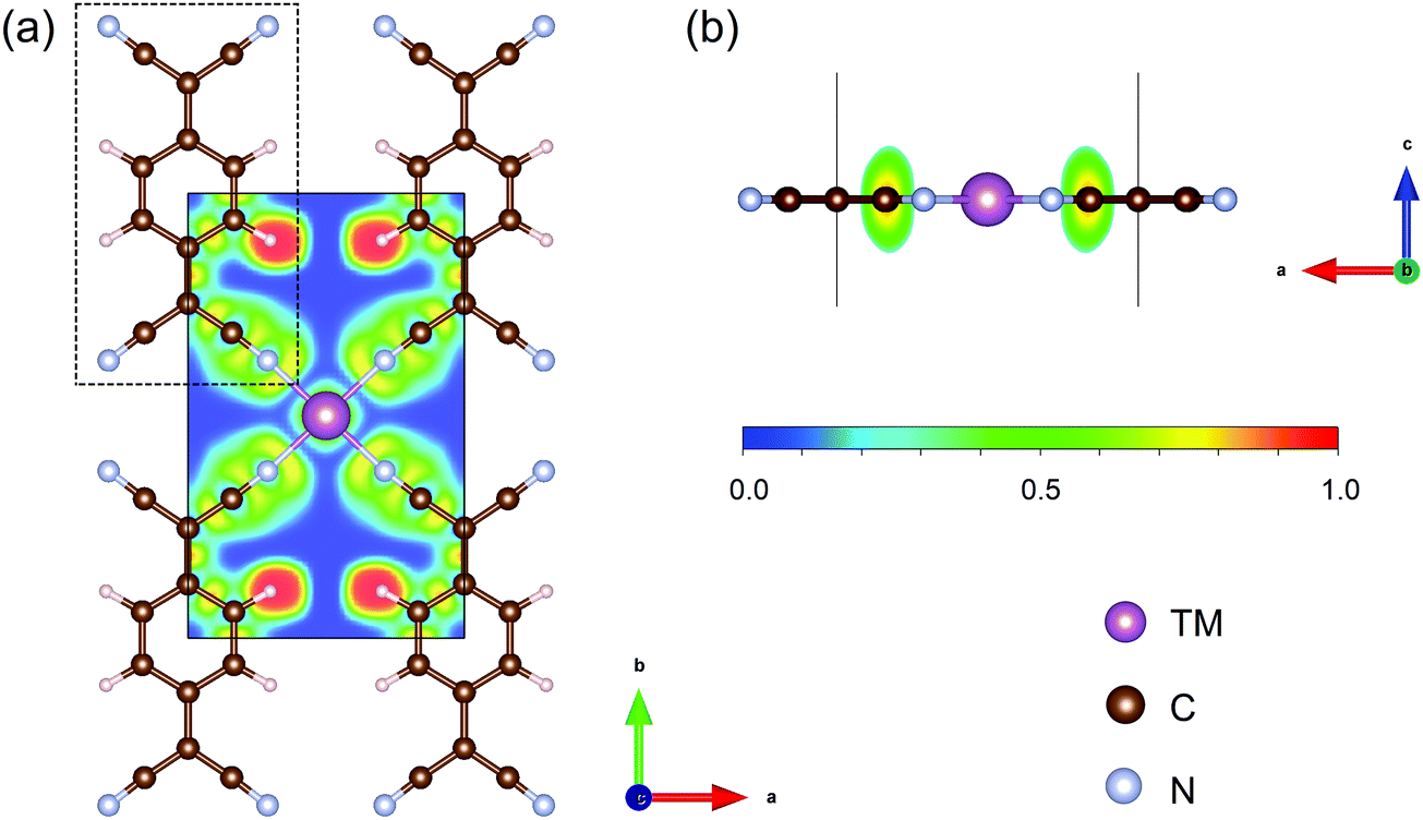 | ||
| Fig. 1 (a) Top and (b) side view of the optimized structure of Sc-TCNQ and the corresponding electron localized function contour map. Sc, C, N, and H atoms are represented in purple, brown, cyan, and pale pink, respectively. Black solid line denotes the cell boundary of Sc-TCNQ, and the dashed line denotes the TCNQ molecule. Isodensity values for ELF map are shown below Fig. 1b. | ||
The N2 adsorption and activation of the NN triple bond is the first and vital step for the NRR.12,13 In this context, before proceeding to study the NRR reaction pathways, we first examine the N2 adsorption on TM-TCNQ. Two adsorption patterns of N2 are considered—side-on configuration with both N atoms binding with the TM atom (active site for the NRR), and end-on configuration with one of the N atoms binding with the TM atom (Fig. S1, ESI†). Each configuration could lead to different NRR reaction pathways. From pioneering theoretical investigations, it can be deduced that the NRR is a complicated process and several pathways have been concluded.25,27,63 For the end-on configuration, distal, alternating, and their mixed mechanisms are possible (Fig. S2, ESI†). For the side-on configuration, enzymatic, consecutive, and their mixed mechanisms are proposed (Fig. 2). As a result, screening the N2 adsorption ability and configuration on TM-TCNQ for each TM is our top priority.
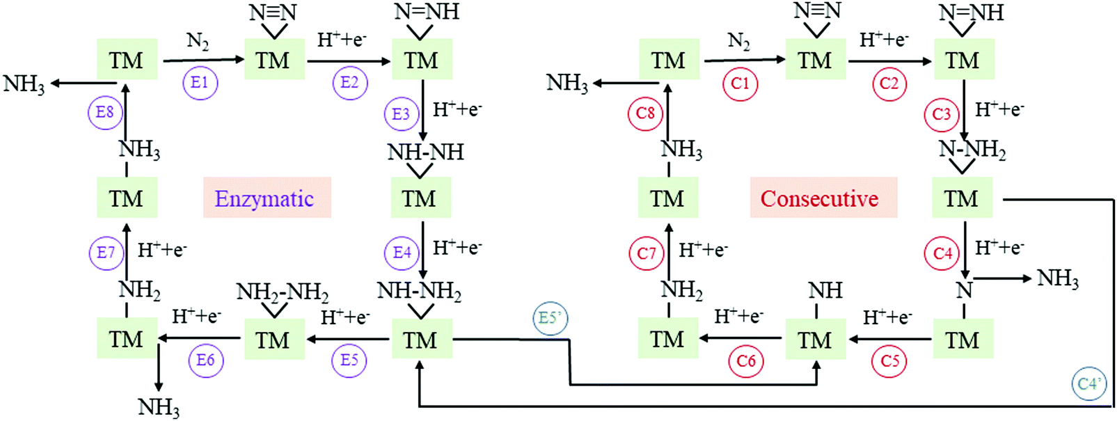 | ||
| Fig. 2 Schematic illustration of enzymatic, consecutive, and their mixed mechanism for the NRR on TM-TCNQ. TM denotes the transition metal atom (active site) in the figures. | ||
N2 adsorption energy values Ead, defined as Ead = E(TM-TCNQ + N2) − E(TM-TCNQ) − E(N2), are calculated and summarized in Table S2 (ESI†) and Fig. 3a for both side-on and end-on patterns on TM-TCNQ. For effective activation of N2, Ead should be negative enough (<−0.5 eV) to ensure the energetically favorable N2 chemisorption.27 From Fig. 3(a), five cases of end-on configuration (Sc-TCNQ, Ti-TCNQ, V-TCNQ, Cr-TCNQ, and Mn-TCNQ), and one case of side-on configuration (Ti-TCNQ) are selected from a total of 34 structures. Nevertheless, three other structures, i.e. Sc-TCNQ and V-TCNQ with a side-on N2 adsorption pattern and Fe-TCNQ with an end-on N2 adsorption pattern can also ensure the chemisorption by forming TM–N bonds with a bond length smaller than 2.4 Å (Fig. S1a and S3a, b, ESI†), even though they exhibit slightly larger Ead values than −0.5 eV. On the other hand, the rest of the structures such as Au-TCNQ (Fig. S3c and d, ESI†) cannot form TM–N chemical bonds because of the large distance between TM and N atoms, and therefore N2 molecules cannot be effectively activated. Thus, they are not considered in the following calculations.
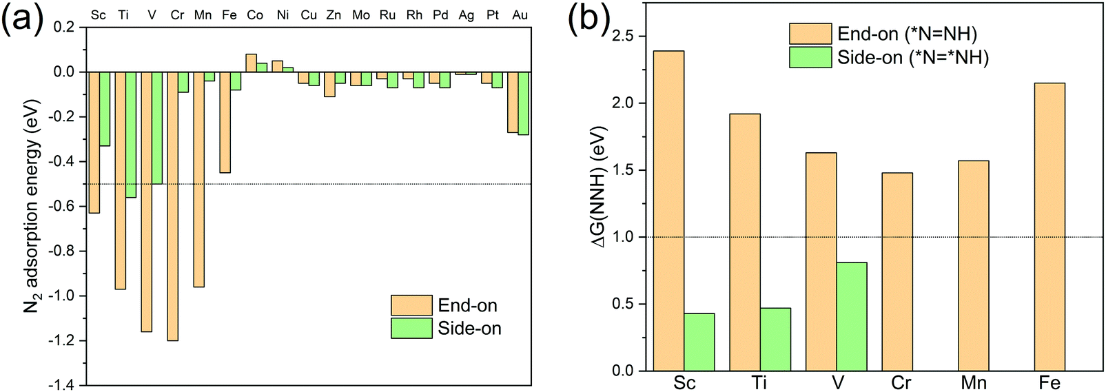 | ||
Fig. 3 The two-step screening strategy for TM-TCNQ electrocatalysts for the NRR. (a) Calculated N2 adsorption energy for both end-on and side-on configurations on TM-TCNQ (TM = Sc-Zn, Mo, Ru-Pd, Ag, Pt, and Au), and (b) Gibbs free energy change values ΔG(NNH) of *NN + (H+ + e−) → *N![[double bond, length as m-dash]](https://www.rsc.org/images/entities/char_e001.gif) NH for Sc-, Ti-, V-, Cr-, Mn-, Fe-TCNQ, and *NN* + (H+ + e−) → *NNH* for Sc-, Ti-, V-TCNQ. NH for Sc-, Ti-, V-, Cr-, Mn-, Fe-TCNQ, and *NN* + (H+ + e−) → *NNH* for Sc-, Ti-, V-TCNQ. | ||
To further screen the remaining nine structures for the NRR, we calculate the Gibbs free energy change for *NN + (H+ + e−) → *NNH (end-on) and *NN* + (H+ + e−) → *NNH* (side-on) (here, * denotes the active sites for the NRR), because these steps (the first hydrogenation step in Fig. S2, ESI† and Fig. 2, respectively) are proven to be the potential limiting step (PLS) for the NRR in many TM-based SACs.26,64–67 To consider the energy barrier values for transforming from end-on configuration *NN to side-on configuration *NN*, we perform CI-NEB calculations to identify the minimum energy path for the transformation on Sc- and Ti-TCNQ as examples. Results (Fig. S4, ESI†) show that the transformation energy barrier values are 0.42 and 0.55 eV for Sc- and Ti-TCNQ, respectively, indicating that our two-step screening process is valid considering the non-simultaneous reaction intermediates involved in the two steps. Fig. 3b indicate that for all six end-on structures, the corresponding Gibbs free energy change values ΔG(NNH) are larger than 1.0 eV. These values are much higher than most of the reported SACs for the NRR and will lead to high overpotential and mediocre NRR performance. On the other hand, for Sc-, Ti-, and V-TCNQ, the side-on N2 adsorption patterns can result in ΔG(NNH) values smaller than 1.0 eV. For N2 adsorption, the difference in energy between side-on and end-on configuration is 0.30, 0.39, and 0.66 eV for Sc-, Ti-, and V-TCNQ, respectively (Fig. 3a), far smaller than the energy difference between end-on and side-on N2 hydrogenation (*NN → *NNH (end-on) and *NN* → *NNH* (side-on)), which are 1.96, 1.45, and 0.82 eV (Fig. 3b). To conclude, after the two-step screening process shown above, we have identified these 3 structures (Sc-, Ti-, and V-TCNQ with side-on consideration) out of the 34 for further investigations because they are more energetically favorable in the two sequential steps.
The electronic structure is an important factor for evaluating the N2 activation on NRR catalysts. Using Sc-TCNQ as an example, we find that the density of states (DOSs) of pure Sc-TCNQ (Fig. 4a) clearly show the metallic character, which facilitates fast charge transfer and is beneficial to the potential electrocatalytic process. The DOS plot for N2 in the gas phase is shown in Fig. 4b, where the lowest unoccupied molecular orbital (LUMO) and the highest occupied molecular orbital (HOMO) are respectively located at πg*2p and σg2p orbitals, which are consistent with the literature.68 The πg*2p, σg2p, and πμ2p orbitals from N2 all match with DOS for Sc-TCNQ, leading to the hybridization and delocalization of orbitals in Sc-TCNQ with N2 adsorption (Fig. 4c). This can lead to the effective activation of N2 on the catalyst, which can be confirmed by the fact that the N–N bond is elongated from 1.098 Å (in gas phase N2) to 1.16 Å (in the adsorbed state).
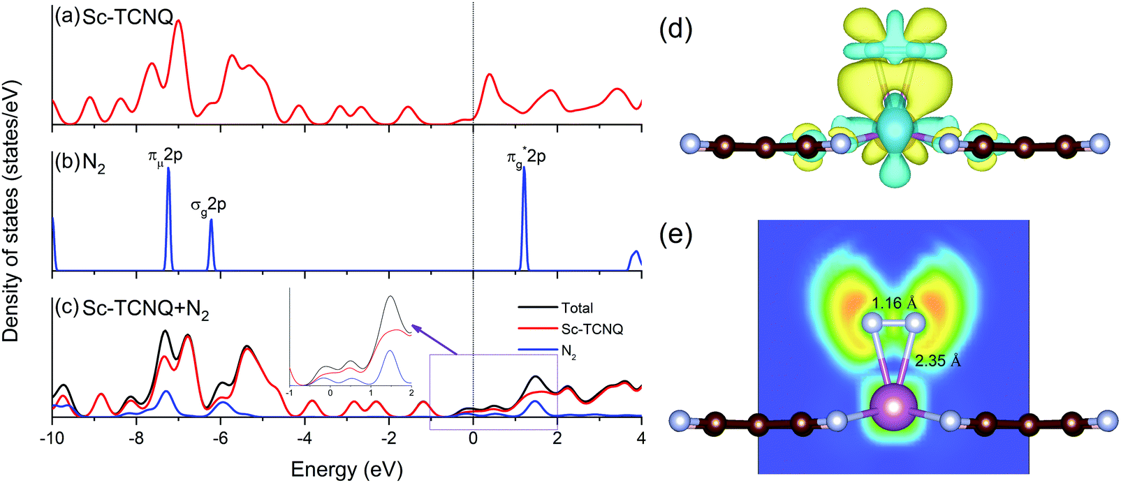 | ||
| Fig. 4 Density of states of (a) pristine Sc-TCNQ, (b) N2 molecule in the gas phase, and (c) Sc-TCNQ with one adsorbed N2 molecule. Fermi level is set to zero and denoted in the black line. Inset in (c) shows the zoomed DOS near the Fermi level. (d) Charge density difference distribution (charge accumulation and depletion are shown in yellow and light blue, respectively) of N2 adsorption with the side-on configuration, and (e) corresponding ELF map with bond lengths of Sc–N and N–N marked in the figure. | ||
Sc, Ti, and V are all early transition metal atoms with both occupied and unoccupied d orbitals, and the corresponding TM-based catalysts are promising for the NRR because of the ‘acceptance–donation’ mechanism.60,69 Unoccupied TM d orbitals can accept lone-pair electrons from N2, and in the meantime, the occupied TM d electrons can be donated to the antibonding orbitals of N2, leading to the strong binding with N2. To unravel the electron transfer during the adsorption of N2, we calculate the charge density difference distribution as Δρ = ρ(Sc-TCNQ + N2) − ρ(Sc-TCNQ) − ρ(N2), where ρ denotes the charge density distribution. Results in Fig. 4d exhibit that significant two-way charge transfer including charge accumulation (yellow) and depletion (light blue) happen around the adsorbed N2 and Sc atoms (active site for the NRR), respectively, confirming that the ‘acceptance–donation’ process happens in Sc-TCNQ. Charge transfer is also validated by Bader charge analysis result that Sc-TCNQ transfers 0.32 e− to the adsorbed N2 molecule. From zoomed DOS near the Fermi level in Fig. 4c, the broadened and partially filled πg*2p can be observed, which can be attributed to the electron donation process. In addition, the ELF map (Fig. 4e) shows that ionic bonds form between Sc and the adsorbed N.
3.2 Gibbs free energy diagrams and NRR reaction pathways
To gain a deeper view of the most probable NRR reaction pathway, we perform calculations on the intermediate in each step (Tables S3–S6, ESI†) to obtain the Gibbs free energy diagram for the NRR. Here we only focus on the enzymatic, consecutive, and the mixed mechanism (Fig. 2) for Sc-, Ti-, and V-TCNQ after the two-step screening process discussed above (Fig. 3) and the result is shown in Fig. 5. The DFT-optimized structures for the relevant intermediates for Sc- and Ti-TCNQ are plotted in Fig. S5 (ESI†) as examples. In the calculations, six consecutive protonation steps are considered, and two ammonia molecules are formed with the general formula of N2 + 6(H+ + e−) → 2NH3.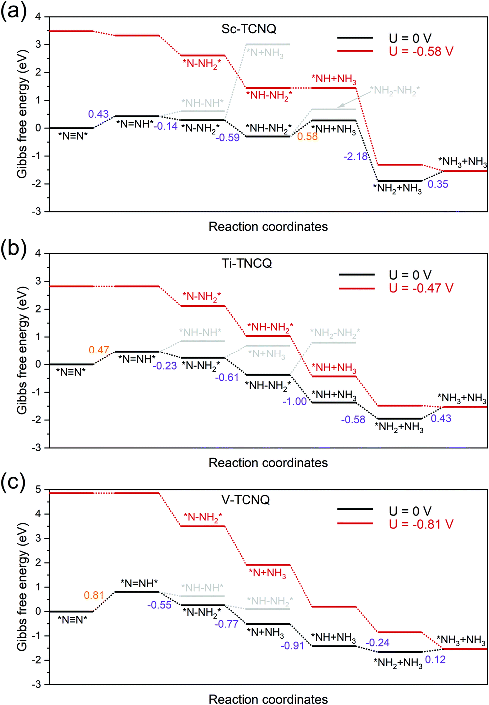 | ||
| Fig. 5 Gibbs free energy diagram for the NRR through the enzymatic/consecutive/mixed mechanism on (a) Sc-TCNQ, (b) Ti-TCNQ, and (c) V-TCNQ at zero and applied potential U. For U = 0, reaction pathways and intermediates with unfavorable Gibbs free energy change are marked in grey, and the Gibbs free energy changes for each step are marked and shown in eV (value marked in orange color denotes the potential limiting step). | ||
For the first hydrogenation step *NN* → *NNH*, all three systems undergo a Gibbs free energy uphill of 0.43, 0.47, and 0.81 eV for Sc-TCNQ, Ti-TCNQ, and V-TCNQ, respectively, and the N–N bonds are elongated from 1.16, 1.17, and 1.17 Å in *NN* to 1.24, 1.24, and 1.23 Å in *NNH*, respectively. The comparison of Gibbs free energy of *NH–NH* and *N–NH2* determines whether the second step goes through the consecutive or enzymatic pathway. From Fig. 5, free energy values of *NH–NH* are higher than those of *N–NH2* for all systems, and *NNH* → *N–NH2* is an exothermic step. The N–N bond length is further elongated to over 1.4 Å. Different preferable pathways occur in the third step, where Sc- and Ti-TCNQ prefer *N–NH2* → *NH–NH2* and V-TCNQ prefers *N–NH2* → *N + NH3 (one ammonia molecule released), but the step is still spontaneous. In the fourth protonation step, Sc- and Ti-TCNQ tend to disengage one NH3 molecule and form *NH. There is an energy uphill for Sc-TCNQ by 0.58 eV, while for Ti- and V-TCNQ, the fourth step is exothermic. The following two steps are *NH → *NH2 → *NH3 and only the last step is endothermic with an energy change of 0.35, 0.43, and 0.12 eV for Sc-, Ti-, and V-TCNQ, respectively. The energetically favorable pathway for Sc- and Ti-TCNQ is an enzymatic-consecutive mixed pathway, while for V-TCNQ, the consecutive pathway is adopted.
The potential-limiting step (PLS) is defined as the reaction step with the highest Gibbs free energy increase and PLS determines the performance of the electrocatalysts. From Fig. 5, we can conclude that the PLS for Ti- and V-TCNQ is the first protonation step *NN* → *NNH* with 0.47 and 0.81 eV free energy change, and for Sc-TCNQ, the fourth step *NH–NH2*→ *NH + NH3 is the PLS (0.58 eV). With a limiting potential of U = −0.58, −0.47, and −0.81 V for Sc-, Ti-, and V-TCNQ, respectively, all reaction pathways can be exothermic (Fig. 5). In addition, by comparing the Gibbs free energy change values for the PLS and those for NH3 desorption (Fig. S6, ESI†), we can conclude that the as-obtained PLS rather than the NH3 desorption determines the energy barrier due to the higher ΔG values. Usually, overpotential (η) is an indicator for determining the catalytic activity, and η for the NRR is defined as η = Uequilibrium − Ulimiting,25 and Uequilibrium is calculated to be −0.25 V in this work (Gibbs free energy change for the total reaction). Therefore, η values for Sc-TCNQ, Ti-TCNQ, and V-TCNQ are 0.33 V, 0.22 V, and 0.56 V, respectively. The overpotential values for Sc- and Ti-TCNQ are much lower than the majority of reported NRR SACs, such as Mo on nitrogen doped graphene (N3-G) (0.34 V),26 Mo on the graphene-boron nitride hybrid sheet (0.42 V),70 and Fe on MoN2 (0.47 V),71 indicating that Sc-TCNQ and Ti-TCNQ are outstanding electrocatalysts for the NRR.
To further understand the NRR catalytic activity of TM-TCNQ, we perform Bader charge analysis along the most favorable reaction pathway, and each intermediate is divided into three moieties: the TCNQ nanosheet (denoted as moiety 1), single TM atom (denoted as moiety 2), and the adsorbed NxHy (moiety 3). Results for Sc- and Ti-TCNQ are plotted in Fig. 6. We can see that for all three moieties, there is obvious charge fluctuation, but generally, the TCNQ nanosheet acts as an electron acceptor, receiving about 1.5 e− for each step while the TM atom donates approximately 2.0 e−. Nevertheless, the fluctuation of Bader charge for the TM is very small, indicating that the TM atom also acts as a transmitter to the charge transfer between the TCNQ nanosheet and the NxHy moiety.
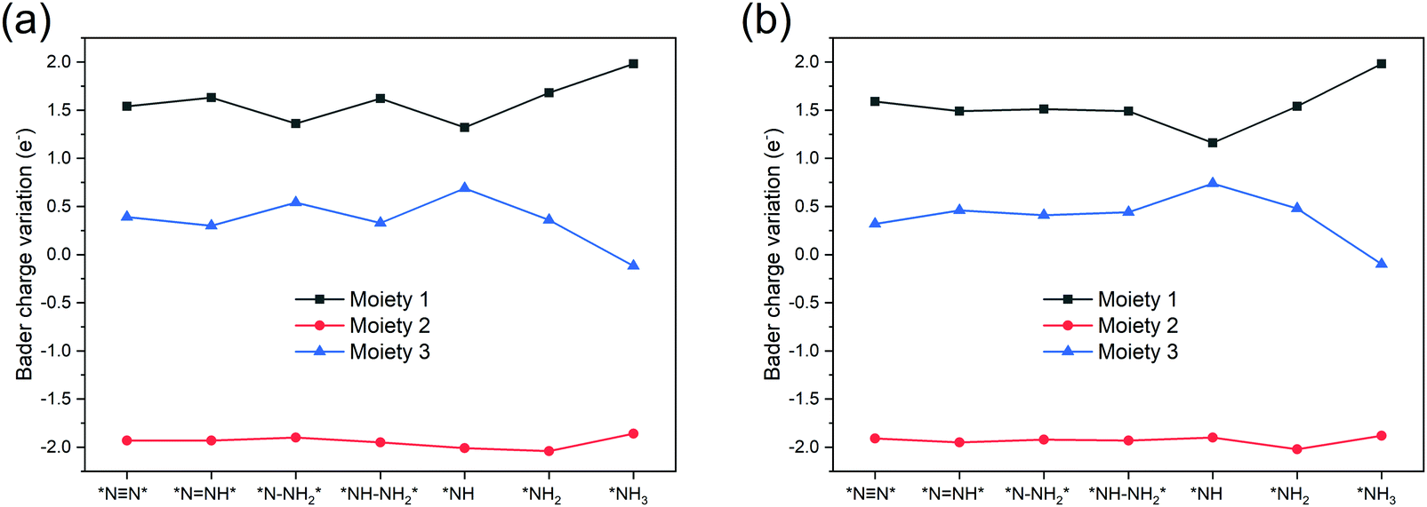 | ||
| Fig. 6 Bader charge variation of the three moieties along the most favorable NRR pathway for (a) Sc-TCNQ, and (b) Ti-TCNQ. | ||
Since the hydrogen evolution reaction (HER) is the major competing reaction for the NRR,72 we also compare the adsorption Gibbs free energy of N2 and H for Sc-, Ti-, and V-TCNQ. The results shown in Fig. S7 (ESI†) indicate that the adsorption of N2 is more energetically favorable than H, ensuring the selectivity of the NRR over the HER.27 Note that the difference between ΔG(N2) and ΔG(H) is slightly larger for Sc-TCNQ than that for Ti-TCNQ and V-TCNQ, indicating that Sc-TCNQ has relatively higher selectivity.
3.3 Stability of TM-TCNQ monolayers (TM = Sc and Ti)
In the final part, we test the stability of Sc- and Ti-TCNQ, which are all good candidates for NRR electrocatalysts. First, to confirm that single metal aggregation will not occur on the surface of TCNQ, we compare the binding energy (Eb) of the single atom and the cohesive energy (Ec) for metal aggregation, which are defined as Eb = ETM-TNCQ − ETNCQ − ETM and Ec = (ETM-bulk − nETM)/n, respectively, where ETM and ETM-bulk represent the energy of single transition metal atom and total energy of transition metals in the most stable crystal form, respectively, while n denotes the number of metal atoms per unit cell of the crystal. Eb values are calculated to be −9.29 and −9.98 eV for Sc and Ti on TCNQ, respectively, while the Ec values are −4.59 and −6.76 eV, respectively, indicating that binding to the substrate is more energetically favorable than aggregating into clusters for both Sc and Ti and the single atoms can be stably deposited onto the substrate as active sites.To ensure the thermal stability of the SACs, we further perform AIMD simulations at 500 K and plot the total energy as a function of simulation time for Sc- and Ti-TCNQ. Results in Fig. 7 exhibit that the total energy of Sc- and Ti-TCNQ quickly converges and oscillates around the equilibrium. The structures after 5 ps AIMD simulations (insets in Fig. 7a and b) do not show an obvious structural reconstruction, and after geometric relaxation, the structures can recover again. These evidences clearly demonstrate that Sc- and Ti-TCNQ are thermally stable with a temperature up to 500 K.
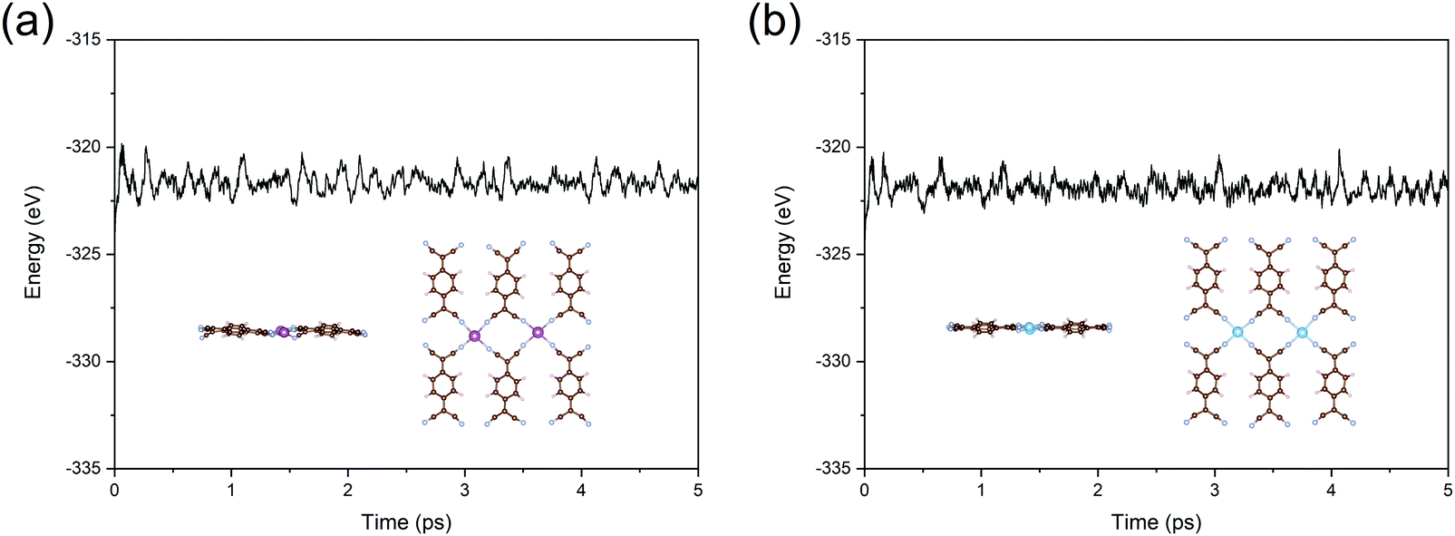 | ||
| Fig. 7 Total energy as a function of time during the AIMD simulations for (a) Sc-TCNQ and (b) Ti-TCNQ. Inset shows the side and top view of the structures after 5 ps AIMD simulations, where C, N, H, Sc, and Ti are represented in brown, cyan, pale pink, purple, and blue, respectively. | ||
4. Conclusions
In this work, by means of first-principles calculations, we have systematically studied the potential application of TM-TCNQ, a group of novel single-atom catalysts, in the electrocatalytic NRR. By using a two-step screening process, we have identified three systems—Sc-, Ti-, and V-TCNQ with side-on N2 adsorption patterns—from 34 structures. N2 adsorption and activation were ensured by the unique electronic properties of TM-TCNQ and the ‘acceptance–donation’ mechanism. Gibbs free energy calculations proved that NRR Sc- and Ti-TCNQ were thermodynamically favorable with low overpotential values of 0.33 and 0.22 V through the enzymatic-consecutive mixed pathway. In addition, the NRR selectivity and stability of the catalysts were also confirmed. Overall, this work provides evidence that Sc- and Ti-TCNQ can be promising NRR electrocatalysts. The findings and methodology in this work may be extended to the design of other single-atom catalysts.Conflicts of interest
The authors declare no competing financial interest.Acknowledgements
This work was supported by the Research Grants Council of the Hong Kong Special Administrative Region, China (Project No. PolyU152140/19E), the Hong Kong Polytechnic University (Project No. Q54V and RH9G), the National Natural Science Foundation of China (No. 11804286), the Fundamental Research Funds for the Central Universities (Grant No. 19lgpy263), and the Scientific and Technical Innovation Action Plan (Hong Kong, Macao and Taiwan Science & Technology Cooperation Project of Shanghai Science and Technology Committee: 19160760600). The DFT calculations were partially performed on Apollo cluster at the Department of Applied Physics, the Hong Kong Polytechnic University.References
- V. Smil, Enriching the earth: Fritz Haber, Carl Bosch, and the transformation of world food production, MIT press, 2004 Search PubMed.
- J. N. Galloway, A. R. Townsend, J. W. Erisman, M. Bekunda, Z. Cai, J. R. Freney, L. A. Martinelli, S. P. Seitzinger and M. A. Sutton, Science, 2008, 320, 889–892 CrossRef CAS PubMed.
- C. Zamfirescu and I. Dincer, J. Power Sources, 2008, 185, 459–465 CrossRef CAS.
- D. Bernhardt and J. Reilly II, Mineral Commodity Summaries 2019, Department of the Interior (DOI), US Geological Survey, Reston, USA, 2019 Search PubMed.
- C. J. van der Ham, M. T. Koper and D. G. Hetterscheid, Chem. Soc. Rev., 2014, 43, 5183–5191 RSC.
- M. A. Shipman and M. D. Symes, Catal. Today, 2017, 286, 57–68 CrossRef CAS.
- X. Cui, C. Tang and Q. Zhang, Adv. Energy Mater., 2018, 8, 1800369 CrossRef.
- S. L. Foster, S. I. P. Bakovic, R. D. Duda, S. Maheshwari, R. D. Milton, S. D. Minteer, M. J. Janik, J. N. Renner and L. F. Greenlee, Nat. Catal., 2018, 1, 490–500 CrossRef.
- W. Guo, K. Zhang, Z. Liang, R. Zou and Q. Xu, Chem. Soc. Rev., 2019, 48, 5658–5716 RSC.
- A. J. Martín, T. Shinagawa and J. Pérez-Ramírez, Chem, 2019, 5, 263–283 Search PubMed.
- C. Guo, J. Ran, A. Vasileff and S.-Z. Qiao, Energy Environ. Sci., 2018, 11, 45–56 RSC.
- J. H. Montoya, C. Tsai, A. Vojvodic and J. K. Norskov, ChemSusChem, 2015, 8, 2180–2186 CrossRef CAS PubMed.
- E. Skúlason, T. Bligaard, S. Gudmundsdóttir, F. Studt, J. Rossmeisl, F. Abild-Pedersen, T. Vegge, H. Jónsson and J. K. Nørskov, Phys. Chem. Chem. Phys., 2012, 14, 1235–1245 RSC.
- J. G. Howalt, T. Bligaard, J. Rossmeisl and T. Vegge, Phys. Chem. Chem. Phys., 2013, 15, 7785–7795 RSC.
- Á. B. Höskuldsson, Y. Abghoui, A. B. Gunnarsdóttir and E. Skúlason, ACS Sustainable Chem. Eng., 2017, 5, 10327–10333 CrossRef.
- Y. Abghoui, A. L. Garden, J. G. Howalt, T. Vegge and E. Skúlason, ACS Catal., 2015, 6, 635–646 CrossRef.
- L. M. Azofra, N. Li, D. R. MacFarlane and C. Sun, Energy Environ. Sci., 2016, 9, 2545–2549 RSC.
- Y. Ying, K. Fan, X. Luo and H. Huang, J. Mater. Chem. A, 2019, 7, 11444–11451 RSC.
- X. Li, X. Yang, Y. Huang, T. Zhang and B. Liu, Adv. Mater., 2019, 31, 1902031 CrossRef CAS PubMed.
- H. Jin, C. Guo, X. Liu, J. Liu, A. Vasileff, Y. Jiao, Y. Zheng and S. Z. Qiao, Chem. Rev., 2018, 118, 6337–6408 CrossRef CAS PubMed.
- L. M. Yang, V. Bacic, I. A. Popov, A. I. Boldyrev, T. Heine, T. Frauenheim and E. Ganz, J. Am. Chem. Soc., 2015, 137, 2757–2762 CrossRef CAS PubMed.
- B. Song, Y. Zhou, H. M. Yang, J. H. Liao, L. M. Yang, X. B. Yang and E. Ganz, J. Am. Chem. Soc., 2019, 141, 3630–3640 CrossRef CAS PubMed.
- J.-H. Liu, L.-M. Yang and E. Ganz, J. Mater. Chem. A, 2019, 7, 11944–11952 RSC.
- Y. Ying, K. Fan, S. Zhu, X. Luo and H. Huang, J. Phys. Chem. C, 2020, 124, 639–646 CrossRef CAS.
- J. Zhao and Z. Chen, J. Am. Chem. Soc., 2017, 139, 12480–12487 CrossRef CAS PubMed.
- W. Zhao, L. Zhang, Q. Luo, Z. Hu, W. Zhang, S. Smith and J. Yang, ACS Catal., 2019, 9, 3419–3425 CrossRef CAS.
- C. Ling, Y. Ouyang, Q. Li, X. Bai, X. Mao, A. Du and J. Wang, Small Methods, 2018, 3, 1800376 CrossRef.
- X. Chen, X. Zhao, Z. Kong, W.-J. Ong and N. Li, J. Mater. Chem. A, 2018, 6, 21941–21948 RSC.
- Z. Chen, J. Zhao, C. R. Cabrera and Z. Chen, Small Methods, 2018, 3, 1800368 CrossRef.
- H. Yin, S.-L. Li, L.-Y. Gan and P. Wang, J. Mater. Chem. A, 2019, 7, 11908–11914 RSC.
- L. M. Azofra, C. Sun, L. Cavallo and D. R. MacFarlane, Chem. – Eur. J., 2017, 23, 8275–8279 CrossRef CAS PubMed.
- T. Yang, T. T. Song, S. Wang, D. Chi, L. Shen, M. Yang and Y. P. Feng, Nano Energy, 2020, 68, 104304 CrossRef CAS.
- Z. Geng, Y. Liu, X. Kong, P. Li, K. Li, Z. Liu, J. Du, M. Shu, R. Si and J. Zeng, Adv. Mater., 2018, 30, 1803498 CrossRef PubMed.
- L. Han, X. Liu, J. Chen, R. Lin, H. Liu, F. Lu, S. Bak, Z. Liang, S. Zhao, E. Stavitski, J. Luo, R. R. Adzic and H. L. Xin, Angew. Chem., Int. Ed., 2019, 58, 2321–2325 CrossRef CAS PubMed.
- H. Tao, C. Choi, L.-X. Ding, Z. Jiang, Z. Han, M. Jia, Q. Fan, Y. Gao, H. Wang, A. W. Robertson, S. Hong, Y. Jung, S. Liu and Z. Sun, Chem, 2019, 5, 204–214 CAS.
- F. Lü, S. Zhao, R. Guo, J. He, X. Peng, H. Bao, J. Fu, L. Han, G. Qi, J. Luo, X. Tang and X. Liu, Nano Energy, 2019, 61, 420–427 CrossRef.
- M. Yoon, R. Srirambalaji and K. Kim, Chem. Rev., 2011, 112, 1196–1231 CrossRef PubMed.
- X. L. Wang, L. Z. Dong, M. Qiao, Y. J. Tang, J. Liu, Y. Li, S. L. Li, J. X. Su and Y. Q. Lan, Angew. Chem., Int. Ed., 2018, 57, 9660–9664 CrossRef CAS PubMed.
- Q. Cui, G. Qin, W. Wang, K. R. Geethalakshmi, A. Du and Q. Sun, J. Mater. Chem. A, 2019, 7, 14510–14518 RSC.
- X. Shi, C. Lin, C. Minot, T.-C. Tseng, S. L. Tait, N. Lin, R. Zhang, K. Kern, J. Cerdá and M. A. Van Hove, J. Phys. Chem. C, 2010, 114, 17197–17204 CrossRef CAS.
- T.-C. Tseng, N. Abdurakhmanova, S. Stepanow and K. Kern, J. Phys. Chem. C, 2011, 115, 10211–10217 CrossRef CAS.
- N. Abdurakhmanova, T.-C. Tseng, A. Langner, C. Kley, V. Sessi, S. Stepanow and K. Kern, Phys. Rev. Lett., 2013, 110, 027202 CrossRef CAS PubMed.
- Q. Deng, J. Zhao, T. Wu, G. Chen, H. A. Hansen and T. Vegge, J. Catal., 2019, 370, 378–384 CrossRef CAS.
- N. Wang, L. Feng, Y. Shang, J. Zhao, Q. Cai and P. Jin, RSC Adv., 2016, 6, 72952–72958 RSC.
- Q. Deng, T. Wu, G. Chen, H. A. Hansen and T. Vegge, Phys. Chem. Chem. Phys., 2018, 20, 5173–5179 RSC.
- J.-H. Liu, L.-M. Yang and E. Ganz, J. Mater. Chem. A, 2019, 7, 3805–3814 RSC.
- G. Kresse and J. Furthmüller, Phys. Rev. B: Condens. Matter Mater. Phys., 1996, 54, 11169 CrossRef CAS PubMed.
- G. Kresse and D. Joubert, Phys. Rev. B: Condens. Matter Mater. Phys., 1999, 59, 1758 CrossRef CAS.
- J. P. Perdew, K. Burke and M. Ernzerhof, Phys. Rev. Lett., 1996, 77, 3865 CrossRef CAS PubMed.
- S. Grimme, J. Antony, S. Ehrlich and H. Krieg, J. Chem. Phys., 2010, 132, 154104 CrossRef PubMed.
- W. Tang, E. Sanville and G. Henkelman, J. Phys.: Condens. Matter, 2009, 21, 084204 CrossRef CAS PubMed.
- S. Nosé, J. Chem. Phys., 1984, 81, 511–519 CrossRef.
- W. G. Hoover, Phys. Rev. A: At., Mol., Opt. Phys., 1985, 31, 1695–1697 CrossRef PubMed.
- G. Henkelman, B. P. Uberuaga and H. Jónsson, J. Chem. Phys., 2000, 113, 9901–9904 CrossRef CAS.
- K. Momma and F. Izumi, J. Appl. Crystallogr., 2011, 44, 1272–1276 CrossRef CAS.
- V. Wang, N. Xu, J.-C. Liu, G. Tang and W. Geng, 2019, arXiv preprint arXiv:1908.08269.
- A. A. Peterson, F. Abild-Pedersen, F. Studt, J. Rossmeisl and J. K. Nørskov, Energy Environ. Sci., 2010, 3, 1311–1315 RSC.
- J. K. Nørskov, J. Rossmeisl, A. Logadottir, L. Lindqvist, J. R. Kitchin, T. Bligaard and H. Jonsson, J. Phys. Chem. B, 2004, 108, 17886–17892 CrossRef.
- P. W. Atkins, Atkins’ physical chemistry, Oxford University Press, Oxford, 11th edn, 2018 Search PubMed.
- C. Ling, X. Niu, Q. Li, A. Du and J. Wang, J. Am. Chem. Soc., 2018, 140, 14161–14168 CrossRef CAS PubMed.
- S. Zhang, Q. Wang, Y. Kawazoe and P. Jena, J. Am. Chem. Soc., 2013, 135, 18216–18221 CrossRef CAS PubMed.
- T. Yu, Z. Zhao, L. Liu, S. Zhang, H. Xu and G. Yang, J. Am. Chem. Soc., 2018, 140, 5962–5968 CrossRef CAS PubMed.
- X. F. Li, Q. K. Li, J. Cheng, L. Liu, Q. Yan, Y. Wu, X. H. Zhang, Z. Y. Wang, Q. Qiu and Y. Luo, J. Am. Chem. Soc., 2016, 138, 8706–8709 CrossRef CAS PubMed.
- C. Liu, Q. Li, J. Zhang, Y. Jin, D. R. MacFarlane and C. Sun, J. Mater. Chem. A, 2019, 7, 4771–4776 RSC.
- B. Huang, N. Li, W.-J. Ong and N. Zhou, J. Mater. Chem. A, 2019, 7, 27620–27631 RSC.
- L. Li, B. Li, Q. Guo and B. Li, J. Phys. Chem. C, 2019, 123, 14501–14507 CrossRef CAS.
- C. Ling, X. Bai, Y. Ouyang, A. Du and J. Wang, J. Phys. Chem. C, 2018, 122, 16842–16847 CrossRef CAS.
- J. C. Liu, X. L. Ma, Y. Li, Y. G. Wang, H. Xiao and J. Li, Nat. Commun., 2018, 9, 1610 CrossRef PubMed.
- M.-A. Légaré, G. Bélanger-Chabot, R. D. Dewhurst, E. Welz, I. Krummenacher, B. Engels and H. Braunschweig, Science, 2018, 359, 896–900 CrossRef PubMed.
- Y. Huang, T. Yang, L. Yang, R. Liu, G. Zhang, J. Jiang, Y. Luo, P. Lian and S. Tang, J. Mater. Chem. A, 2019, 7, 15173–15180 RSC.
- Q. Li, L. He, C. Sun and X. Zhang, J. Phys. Chem. C, 2017, 121, 27563–27568 CrossRef CAS.
- Z. W. Seh, J. Kibsgaard, C. F. Dickens, I. Chorkendorff, J. K. Norskov and T. F. Jaramillo, Science, 2017, 355, eaad4998 CrossRef PubMed.
Footnote |
| † Electronic supplementary information (ESI) available. See DOI: 10.1039/d0ma00348d |
| This journal is © The Royal Society of Chemistry 2020 |