DOI:
10.1039/D0MA00277A
(Paper)
Mater. Adv., 2020,
1, 1307-1317
The interfacial degradation mechanism of polymer:fullerene bis-adduct solar cells and their stability improvement†
Received
5th May 2020
, Accepted 30th June 2020
First published on 30th June 2020
Abstract
Although fullerene bis-adducts have been widely used in polymer solar cells for their high LUMO energy level and good performance, the degradation behavior of this class of solar cells has not been well understood. In this paper, the performance and stability of the solar cells based on P3HT:fullerene bis-adducts, including bis-PC61BM and ICBA, were systematically investigated. Different from the P3HT:PC61BM cell, these bis-adduct based cells showed fast open circuit (VOC) and fill factor (FF) decays. The partial recovery of VOC and FF of the aged cells by renewing the MoO3/Al electrode indicated that degradation at the photoactive layer and MoO3 interface is the main reason for VOC and FF decays. The X-ray photoelectronic spectroscopy analysis confirmed that under light illumination, Mo6+ of MoO3 is partially reduced to Mo5+. By inserting a thin layer of C60, both MoO3 reduction and performance decays are slowed down, confirming that photoreduction of MoO3 by P3HT is the degradation mechanism for P3HT:bis-PC61BM cells. Finally, we found that doping a polymer:fullerene bis-adduct layer with piperazine increases the fullerene content on the surface of the photoactive layer, which consequently lowers the reduction of Mo6+ and improves the stability of the solar cells. This work gives a detailed understanding of the interfacial degradation of PSCs and provides effective solutions, which has important guiding significance for improving the stability of different types of polymer solar cells.
1. Introduction
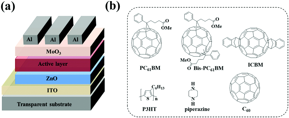
Polymer solar cells (PSCs) have seen rapid development in recent years with the power conversion efficiency (PCE) boosted to over 17%1,2 for single junction solar cells and 11.7%3 for large-area modules. Owing to their high electron affinity and mobility, fullerene and its derivatives have been universal acceptor materials for PSCs for the past two decades.4–6 Although non-fullerene acceptors are currently dominating the research and development of PSCs, fullerene derivatives still play a pivotal role in high performance ternary7–9 or tandem cells.2 In the fullerene acceptor family, [6,6]-phenyl-C61-butyric acid methyl ester (PC61BM) and [6,6]-phenyl-C71-butyric acid methyl ester (PC71BM) are the two most used acceptors in PSCs for their good solubility, high electron mobility, and matched energy levels with a wide range of polymer donors.10–12 Beyond them, the fullerene bis-adducts like the bis-adduct of phenyl-C61-butyric acid methyl ester (bis-PC61BM) and the indene-C60 bis-adduct (ICBA, see Fig. 1 for the chemical structure) also attract much attention for their high-lying lowest unoccupied molecular orbital (LUMO) levels, which is good for achieving high open circuit voltage (VOC) of the cells,9,13–15 since the VOC of PSCs is almost directly proportional to the gap between the highest occupied molecular orbital (HOMO) level of the donor and the LUMO level of the acceptor.16,17 The high VOC is especially important in tandem solar cells. For example, You et al. reported tandem PSCs using P3HT:ICBA as the front cell, in which a high VOC of 1.53 V was achieved.6
 |
| | Fig. 1 Device structure (a) of PSCs, and molecular structures (b) of PC61BM, bis-PC61BM, ICBA, C60, P3HT, and piperazine. | |
With the increase of power conversion efficiency, the stability of PSCs has been recognized as the next most important issue to be solved before the commercialization of PSCs. Numerous studies have shown that most PSCs exhibit a fast exponential “burn-in” degradation, which dominates the overall performance decay of PSCs.18,19 For PC61BM based solar cells, it was reported that photon-induced dimerization is the main reason for the “burn-in” decay of PSCs, where short circuit current (JSC) decay dominates the decay process.20–22 Our recent work further proved that such a “burn-in” degradation is dependent on the external load. Therefore, we ascribed the formation of PC61BM dimers to the triplet state related photo dimerization.22 On the basis of this finding, doping the polymer:fullerene film with a triplet quencher for fullerene molecules – organic amines, such as piperazine – is able to suppress the “burn-in” process, and less than 10% performance decay after light illumination over 1000 h was achieved.23 The bis-substituted C60 derivatives are not prone to dimerization due to steric hindrance,24 however, as will be shown later in this paper, that the fast degradation of fullerene bis-adduct based PSCs occurs as well, which suggests a different degradation mechanism for the polymer:fullerene bis-adduct solar cells. To date, no research work was reported on the degradation mechanism of fullerene bis-adduct based PSCs.
Since fullerene bis-adducts have shown potential application in high performance tandem or ternary solar cells for their high lying LUMO energy level, it is still of high interest to investigate the degradation behavior of this class of cells. In this paper, for the first time, we systematically investigate the degradation behaviors of P3HT:fullerene bis-adduct (both bis-PC61BM and ICBA) cells. Unlike PC61BM cells, where JSC decays dominate the overall performance degradation, these fullerene bis-adduct based solar cells also showed fast open circuit (VOC) and fill factor (FF) decays. By analyzing the interfacial properties of the solar cells during degradation, it can be clearly proved that the interfacial photoreduction of the MoO3 layer by a conjugated polymer is the main reason leading to the fast VOC and FF decays. Based on this finding, the methods to improve the stability of the cells are established, including doping the photoactive layer with piperazine and depositing a thin layer of C60 on the surface of the active layer. The current work gives a detailed understanding of the interfacial degradation of polymer:fullerene cells, which will guide in improving the stability of different types of polymer solar cells.
2. Experimental
2.1 Materials
Regioregular poly(3-hexylthiophene) (SMI-P3HT, Mn = 5.0 × 10⁴ g mol−1), PC61BM, bis-PC61BM, and ICBA were purchased from Solarmer Materials Inc. (Beijing). C60 was provided by Suzhou Dade Carbon Nanotechnology Co. Ltd. Piperazine was obtained from J&K China Chemical Co. Ltd. ZnO nanoparticles were synthesized by the reaction of KOH and Zn(OAc)2 in methanol solvent as reported by Beek et al.25,26
2.2 Fabrication of inverted solar cells
Inverted PSCs with an architecture of ITO/ZnO/active layer/MoO3/Al were fabricated. The patterned ITO glass substrates were cleaned using a detergent, deionized water, acetone and isopropanol, then the precleaned ITO glass substrates were blown using a nitrogen gun and subsequently treated with UV-ozone for 30 min. Filtered ZnO (10 mg mL−1 in methanol) was spin-coated onto the ITO glass substrates at 2500 rpm for 60 s and baked at 120 °C for 10 min in a N2-filled glovebox. Then, the active layers (P3HT:PC61BM, P3HT:bis-PC61BM, and P3HT:ICBA) were spin coated on the ZnO layers. The blend solutions of P3HT:PC61BM (40 mg mL−1 in 1,2-dichlorobenzene (o-DCB) and a donor![[thin space (1/6-em)]](https://www.rsc.org/images/entities/char_2009.gif) :acceptor ratio of 1:1), P3HT:bis-PC61BM (44 mg mL−1 in o-DCB and donor:acceptor ratio of 1:1.2) and P3HT:ICBA (40 mg mL−1 in o-DCB and donor:acceptor ratio of 1:1) were mixed with varying amounts of piperazine additives (0, 0.5, 1, 5 and 10 wt% based on the total weight of the active layer materials) and stirred at 50 °C overnight. The mixture solutions were spin-coated at 600 rpm for 60 s onto ZnO layers. Then, the wet blend films were put into covered Petri dishes for 2 h. Subsequently, the active layers were annealed at 120 °C for 10 min in a N2-filled glove box. Finally, MoO3 (10 nm) and Al (100 nm) were sequentially vacuum deposited on top of the active layer at pressure <5 × 10⁻⁴ Pa. For devices with C60 insertion, before the deposition of MoO3/Al, C60 films of different thicknesses (0–6 nm) were vacuum evaporated onto the active layer at pressure <5 × 10⁻⁴ Pa. The effective photovoltaic area, defined by the geometrical overlap between the bottom cathode electrode and the top anode, was 0.09 cm2. The molecular structures of P3HT, PC61BM, bis-PC61BM, ICBA, C60 and piperazine as well as the device structure are shown in Fig. 1.
:acceptor ratio of 1:1), P3HT:bis-PC61BM (44 mg mL−1 in o-DCB and donor:acceptor ratio of 1:1.2) and P3HT:ICBA (40 mg mL−1 in o-DCB and donor:acceptor ratio of 1:1) were mixed with varying amounts of piperazine additives (0, 0.5, 1, 5 and 10 wt% based on the total weight of the active layer materials) and stirred at 50 °C overnight. The mixture solutions were spin-coated at 600 rpm for 60 s onto ZnO layers. Then, the wet blend films were put into covered Petri dishes for 2 h. Subsequently, the active layers were annealed at 120 °C for 10 min in a N2-filled glove box. Finally, MoO3 (10 nm) and Al (100 nm) were sequentially vacuum deposited on top of the active layer at pressure <5 × 10⁻⁴ Pa. For devices with C60 insertion, before the deposition of MoO3/Al, C60 films of different thicknesses (0–6 nm) were vacuum evaporated onto the active layer at pressure <5 × 10⁻⁴ Pa. The effective photovoltaic area, defined by the geometrical overlap between the bottom cathode electrode and the top anode, was 0.09 cm2. The molecular structures of P3HT, PC61BM, bis-PC61BM, ICBA, C60 and piperazine as well as the device structure are shown in Fig. 1.
2.3 Sample preparation for XPS and UPS characterization
The samples for X-ray photoelectron spectroscopy (XPS) and Ultraviolet Photoelectron Spectroscopy (UPS) characterization were prepared and tested in an inert atmosphere or under vacuum to eliminate the influence of air. Clean ITO glass substrates were treated with UV-ozone for 10 min. Then, P3HT:bis-PC61BM(150 nm) films were spin coated on the ITO glass. The wet blend films were then put into covered Petri dishes for 2 h. Subsequently, the active layers were annealed at 120 °C for 10 min. Finally, MoO3 (5 nm) was vacuum deposited on top of the active layer at pressure <5 × 10⁻⁴ Pa. After that, the samples were illuminated with a white LED for 0 or 5 h, and the illumination is performed from the MoO3 side. All the above experimental processes were carried out in a N2-filled glove box. At last, the samples were put into a N2-filled transition chamber and taken to the test center, where the samples were directly vacuumed and tested.
2.4 Characterization
Characterization of active layers.
Atomic force microscopy (AFM) images of the films were recorded using a Dimension 3100 atomic force microscope. The Grazing-incidence wide-angle X-ray scattering (GIWAXS) was tested using a XEUSS saxs/waxs system, Xenocs (France). XPS, ARXPS (angle resolved XPS) and UPS characterization was performed on a PHI 5000 Versa Probe III X-ray photoelectron spectroscope. The C/S and C–O/C–C ratios are the average values of the three sets of test data. The absorption spectra of films were measured using a Lambda 750 UV/vis/NIR spectrophotometer (PerkinElmer).
PSC performance characterization.
The J–V curves of PSCs were recorded in a glove box using a Keithley 2400 source meter under illumination with simulated AM 1.5G sunlight (ss150 solar simulator, Zolix). The external quantum efficiency (EQE) spectra were recorded under illumination by a simulated one sun operation condition using bias light from a 532 nm solid state laser. Light from a 150 W tungsten halogen lamp (Osram 64610) was used as a probe light and was modulated with a mechanical chopper before passing through the monochromator (Zolix, Omni-k300) to select the wavelength. The response was recorded as the voltage using an I–V converter (DNR-IV Convertor, Suzhou D&R Instruments), using a lock-in amplifier (Stanford Research Systems SR 830). A calibrated Si cell was used as a reference. The device for EQE measurement was kept behind a quartz window in a nitrogen-filled container.
PSC long-term stability testing.
The long-term stabilities of unencapsulated devices were tested using a multi-channel solar cell performance decay test system (PVLT-G8001 M, Suzhou D&R Instruments) under testing conditions in accordance with ISOS-L-1. The unencapsulated devices were put inside a glove box (H2O < 10 ppm, O2 < 10 ppm) and continuously illuminated with a LED light (LED array white light, with a color temperature of 5300 K, D&R Light, L-W5300KA-150, Suzhou D&R Instruments). The LED light has a spectral range of 400–870 nm. The illumination light intensity was initially set so the output JSC of devices equaled the JSC measured under standard conditions. The illumination light intensity was monitored by a photodiode (Hamamatsu S1336-8BQ). The J–V curves were periodically swept every half an hour, and the VOC, JSC, FF, and power conversion efficiency (PCE) were recorded. During testing, the device was attached to an external load to match the maximum power output point (mpp), where the load value (R100) was then calculated according to the equation R100 = Vmax/Imax, where Vmax and Imax represent the voltage and current at the mpp point.
3. Results and discussion
3.1 Degradation of P3HT:fullerene solar cells
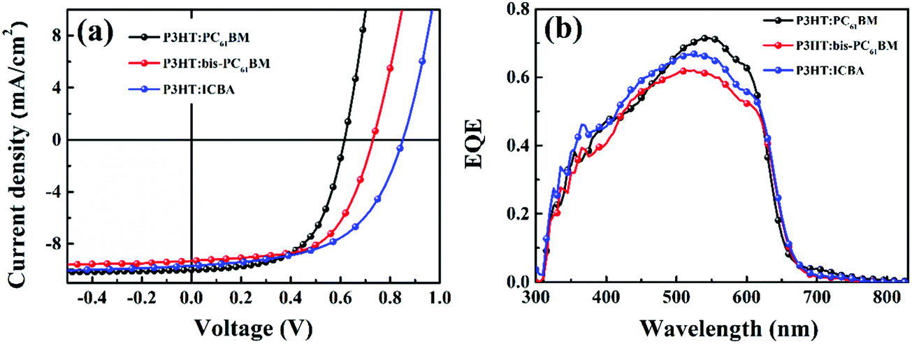
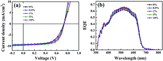
In this work, P3HT was chosen as the donor, because it is the most well investigated polymer and the degradation behaviors of P3HT:PC61BM solar cells have been well studied.22,27,28 We fabricated the P3HT PSCs based on different fullerenes (PC61BM, bis-PC61BM and ICBA) and tested the device performance under standard conditions. Fig. 2 shows the J–V curves and EQE spectra of the cells, and Table 1 lists the device characteristics. The P3HT:PC61BM solar cells show the best PCE of 3.56%, with VOC of 0.60 V, JSC of 10.07 mA cm−2 and FF of 0.59, similar to our previous works.23 For the fullerene bis-adduct solar cells, the devices show higher PCE (4.09% for P3HT:bis-PC61BM cells and 4.53% for P3HT:ICBA cells), which is mainly due to their higher VOC (0.73 V for P3HT:bis-PC61BM cells and 0.85 V for P3HT:ICBA cells), originating from their higher LUMO levels.14,29 All these cells show comparable device performance to those reported in the literature,14,29 and the PCE distribution is rather narrow, making them suitable for device degradation behavior study.
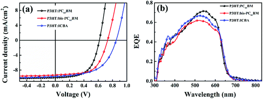 |
| | Fig. 2
J–V curves (a) and EQE spectra (b) of P3HT:PC61BM, P3HT:bis-PC61BM and P3HT:ICBA solar cells. | |
Table 1 Photovoltaic parameters of P3HT:acceptor solar cellsa
| Acceptor |
J
SC (mA cm2) |
V
OC (V) |
FF |
PCEb (%) |
|
The best cell.
The number in brackets is the averaged PCE over 8 individual devices.
|
| PC61BM |
10.07 |
0.60 |
0.59 |
3.56 |
|
|
(9.98 ± 0.15) |
(0.60 ± 0.001) |
(0.59 ± 0.012) |
(3.50 ± 0.15) |
| bis-PC61BM |
9.18 |
0.73 |
0.62 |
4.15 |
|
|
(9.14 ± 0.11) |
(0.73 ± 0.007) |
(0.61 ± 0.016) |
(4.07 ± 0.17) |
| ICBA |
9.69 |
0.85 |
0.55 |
4.53 |
|
|
(9.61 ± 0.15) |
(0.84 ± 0.003) |
(0.55 ± 0.003) |
(4.44 ± 0.09) |
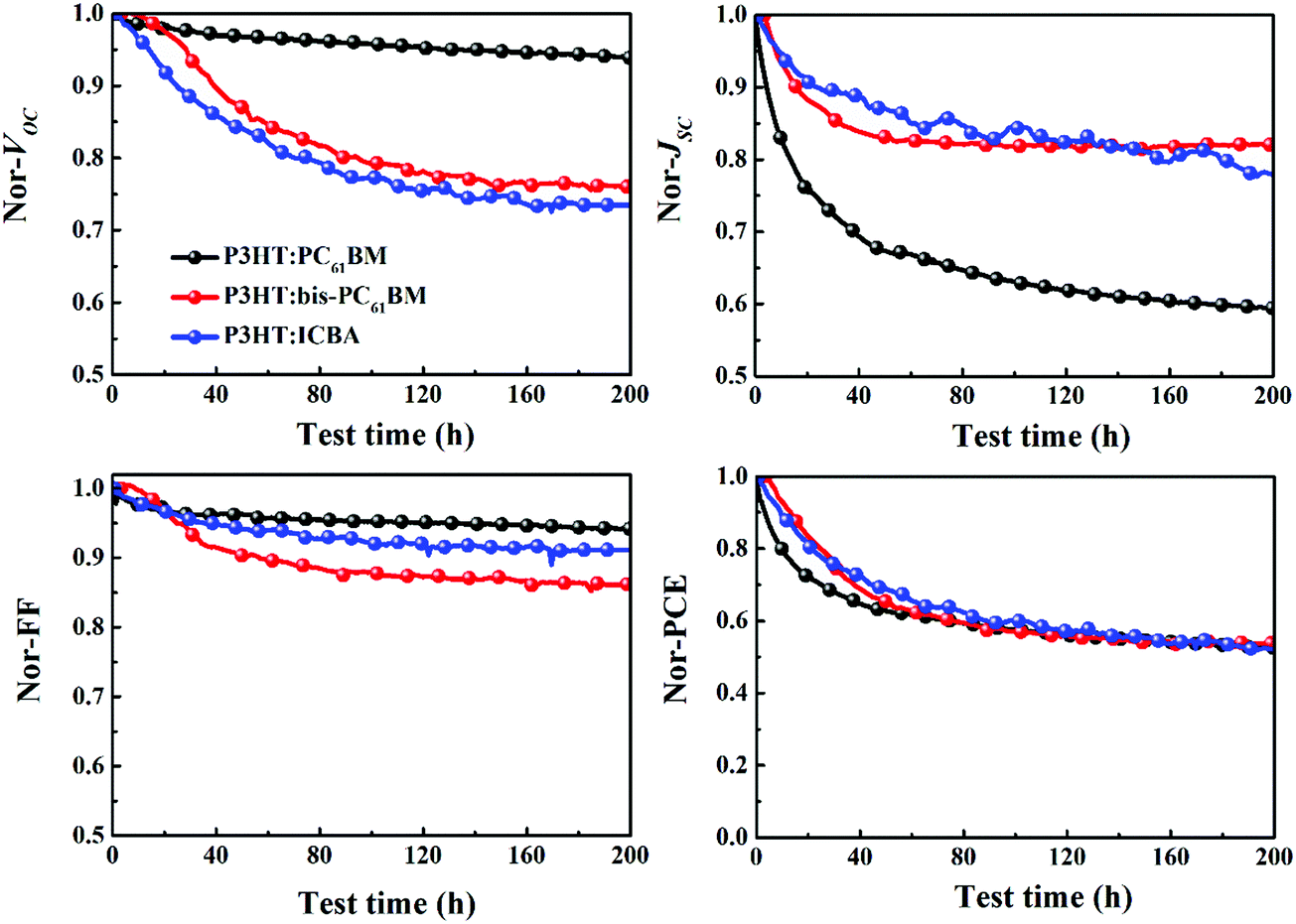
Fig. 3 depicts the evolution of the VOC, JSC, FF and PCE of solar cells aged at mpp with continuous light illumination. As can be seen here, P3HT:PC61BM solar cells undergo a strong “burn-in” loss under operation conditions. After being aged for 200 h, P3HT:PC61BM cells display an overall 48% PCE degradation, where JSC decay (41%) dominates the overall performance loss. Both P3HT:bis-PC61BM and P3HT:ICBA solar cells show also fast “burn-in” degradation, however, VOC decay is more prominent than JSC decay. After being aged for 200 h, P3HT:bis-PC61BM solar cells show 47% PCE degradation, with 24% VOC decay, 19% JSC decay and 14% FF decay, while P3HT:ICBA solar cells show 48% PCE degradation, with 27% VOC decay, 23% JSC decay and 9% FF decay. The faster decay of VOC and FF for fullerene bis-adduct based solar cells suggests that their degradation mechanism is different from that of PC61BM based solar cells. In the following section, we will focus the exploration on the degradation mechanism of the P3HT:bis-PC61BM solar cells.
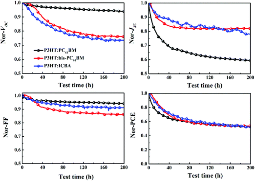 |
| | Fig. 3 Evolution of the VOC, JSC, FF and PCE of P3HT:PC61BM, P3HT:bis-PC61BM and P3HT:ICBA solar cells aged at mpp with continuous light illumination. | |
3.2 Understanding of the degradation mechanism of P3HT:bis-PC61BM cells
To investigate the degradation mechanism of P3HT:bis-PC61BM solar cells, the morphologies and absorption of the photoactive layers before and after aging were characterized and compared. Fig. S1a and b (ESI†) show the 2D GIWAXS patterns of P3HT:bis-PC61BM blend films before and after aging. The corresponding diffraction profiles along the in-plane (qxy) and out-of-plane (qz) directions are shown in Fig. S1c and d (ESI†). As can be seen here, there is no obvious morphology change in the photoactive layers before and after aging, suggesting that the crystallinity and molecular stacking of P3HT:bis-PC61BM films hardly change during aging. Knowing that the formation of fullerene dimers would increase the absorption around 320 nm,20,21 we conducted UV-Vis characterization of the bis-PC61BM film exposed to continuous illumination for different hours. As can be seen from Fig. S2 (ESI†), there is hardly a change in film absorption during continuous illumination, indicating that both the chemical components and crystalline structure of the blend film do not change significantly during aging. In other words, the degradation of devices cannot be attributed to the change in the nanomorphology of the photoactive layer.
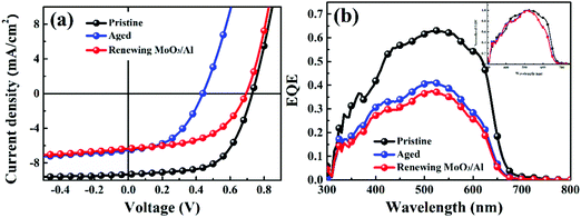
To identify whether the top electrode (MoO3/Al) is the reason for the fast VOC and FF decays of the solar cells, we then renewed the top electrodes (MoO3/Al) of the aged P3HT:bis-PC61BM solar cells using a reported method.22 The top electrodes (MoO3/Al) of the aged devices were removed with a low concentration of sodium hydroxide solution and then the new top electrode (MoO3/Al) was redeposited. The J–V curves, EQE spectra of pristine, aged and renewed P3HT:bis-PC61BM solar cells with renewed MoO3/Al electrodes are shown in Fig. 4. The corresponding photovoltaic performance data are summarized in Table 2. As seen here, the VOC and FF of aged P3HT:bis-PC61BM solar cells are recovered after renewing the MoO3/Al electrode. A VOC of 0.70 V and a FF of 0.52 are measured for the aged cells with the renewed MoO3/Al electrode, which correspond to 96% and 85% recovery of initial values, respectively, while JSC is barely recovered. These results indicate that interfacial degradation should be one of the main reasons for the VOC and FF decays of P3HT:bis-PC61BM solar cells. It is worth noting that the JSC of the aged cells is not recovered over renewing the MoO3/Al electrode, suggesting other reasons causing the JSC decay of the cell. Although the detailed reason for the JSC decay is not fully understood yet, the normalized EQE spectra of the aged cells demonstrate that there should be other reasons related to the photoactive layer (Fig. 4b), not about the morphology but about the efficiency of photon-induced charge separation.
 |
| | Fig. 4
J–V curves (a) and EQE spectra (b) of pristine, aged and renewed P3HT:bis-PC61BM solar cells with new evaporated MoO3/Al electrodes, the insert in (b) shows the normalized EQE spectra of these three cells, showing the changes of spectrum response for the aged cell. | |
Table 2 Photovoltaic parameters of pristine, aged and renewed MoO3/Al solar cells
| Entry |
J
SC (mA·cm2) |
V
OC (V) |
FF |
PCE (%) |
| Pristine |
9.18 |
0.73 |
0.62 |
4.15 |
|
|
(9.14 ± 0.11) |
(0.73 ± 0.007) |
(0.61 ± 0.016) |
(4.07 ± 0.17) |
| Aged |
6.63 |
0.43 |
0.48 |
1.37 |
|
|
(6.58 ± 0.08) |
(0.43 ± 0.008) |
(0.46 ± 0.006) |
(1.31 ± 0.04) |
| New MoO3/Al |
6.34 |
0.70 |
0.53 |
2.35 |
|
|
(6.26 ± 0.24) |
(0.70 ± 0.001) |
(0.52 ± 0.008) |
(2.28 ± 0.05) |
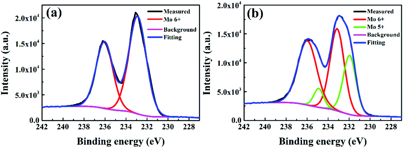
To further understand the detailed reason for interfacial degradation, XPS measurement was carried out on the model P3HT:bis-PC61BM(150 nm)/MoO3 (5 nm) films before and after illumination for 5 h. Fig. 5 shows the XPS spectra of the Mo 3d core level for the pristine and illuminated films. For the fresh MoO3 films (Fig. 5a), the Mo 3d core level exhibits two symmetric peaks, centered at 232.9 and 236.0 eV, which can be attributed to the 3d orbital doublet of Mo6+.30,31 After light illumination for 5 h, XPS peaks turn to be broader (Fig. 5b). By fitting of the peaks, two sets of peaks of 232.9/236.0 and 231.9/234.9 eV can be obtained, which are attributed to the 3d doublets of Mo6+ and Mo5+, respectively.32 The results indicate that Mo6+ is partially reduced to Mo5+ under light illumination. Although the experimental result cannot define the reductant for the reduction of Mo6+ to Mo5+, it is supposed that P3HT must be the one since it has stronger electron donating capability than fullerene derivatives. As will be shown later (Section 3.3.1), the insertion of a thin C60 layer in P3HT:bis-PC61BM can substantially slow down the formation of Mo5+ and suppress the VOC and FF decay (vide infra), which also support the speculation. Nevertheless, the experimental results confirm the occurrence of interfacial reduction of Mo6+ to Mo5+ under light illumination, which is supposed to be a detailed mechanism for the VOC and FF degradation of the solar cells.
 |
| | Fig. 5 XPS spectra of the Mo 3d core level peaks for the MoO3 films deposited on P3HT:bis-PC61BM films before (a) and after (b) illumination for 5 h. | |
To identify whether the degradation of MoO3 occurs at the buried interface or at the top surface, we performed the angle resolved XPS (ARXPS) measurement on different P3HT:bis-PC61BM films. By measuring the collected electrons at various emission angles, ARXPS measurement enables the detection of the elements’ chemical information from different depths. Fig. S3 in the ESI† shows the ARXPS spectra of the Mo 3d core level peaks for the freshly prepared and aged P3HT:bis-PC61BM MoO3 films. Since a slotted aperture is placed in front of the analyzer input lens as an angular filter, the measured ARXPS signal is weaker and noisier. As can be seen from Fig. S3(a) (ESI†), the normalized XPS spectra of Mo 3d core level peaks measured from different angles of the pristine sample are identical. The Mo 3d core level exhibits two symmetric peaks, centered at 232.9 and 236.0 eV, which can be attributed to the 3d orbital doublet of Mo6+. The results indicate that there is no significant difference for the MoO3 from the top surface to the buried interface. In contrast, as seen from Fig. S3(b) (ESI†), the XPS spectra of Mo 3d core level peaks of the aged sample gradually broaden with the increase of detection depth. The broadening of the XPS spectra is attributed to the formation of Mo5+ (vide supra). Therefore, the ARXPS results of the aged P3HT:bis-PC61BM/MoO3 film indicate that the content of Mo5+ increases with the increase of detection depth. In other words, more Mo5+ was measured at the buried interface than at the top surface for the aged P3HT:bis-PC61BM/MoO3 film.
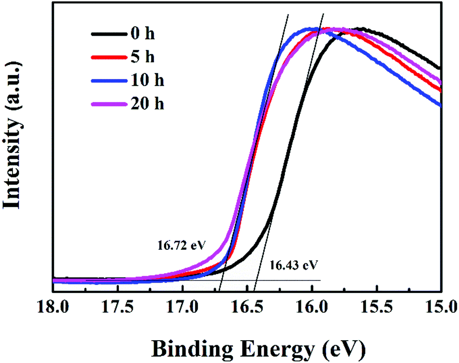
MoO3 is used as the hole transport layer to boost the charge transport efficiency of polymer solar cells, which has been ascribed to the formation of dipoles at the active layer/MoO3 interface, based on the alignment of the highest occupied molecular orbital (HOMO) of the organic layer and the conduction band of MoO3.33 The position of aligned energy levels can be estimated from the work function.34 In order to further understand the mechanism of device performance degradation caused by the reduction of MoO3, UPS spectra of P3HT:bis-PC61BM/MoO3 films illuminated for different hours were tested, as shown in Fig. 6. Based on the UPS spectra, the work function of MoO3 films can be calculated. The results show that after illumination for more than 5 hours, the work function of MoO3 films decreased from 4.78 to 4.50 eV. Greiner et al. reported that the work functions of MoO3 tend to decrease with the decreasing cation oxidation state,35 which is consistent with the XPS (Fig. 5) and UPS (Fig. 6) results, and further confirms the reduction of MoO3. The decrease in the MoO3 work function indicates a decrease of the polarity of the surface of MoO3, this consequently decreases the dipole at the P3HT/MoO3 interface, and therefore decreases the charge transport over the interface.36 In that way, Mo6+ reduction to Mo5+ leads to fast VOC and FF decays of devices, resulting in fast device performance degradation.
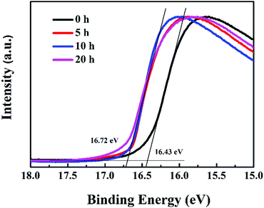 |
| | Fig. 6 UPS spectra of P3HT:bis-PC61BM/MoO3 films before and after illumination for different times. | |
3.3 Stability improvement of P3HT:bis-PC61BM cells
3.3.1 Stability improvement by inserting a thin C60 layer.
To further confirm that interfacial photoreduction of MoO3 with P3HT is the reason for the fast VOC and FF decays of the P3HT:bis-PC61BM cells, PSCs with an additional thin C60 layer (1.5–6 nm) between P3HT:bis-PC61BM and MoO3 were fabricated and tested. Fig. S4 (ESI†) shows the UPS spectra of the P3HT:bis-PC61BM film before and after the deposition of a layer of C60. Based on the UPS, the HOMO level of films can be calculated. As can be seen here, after depositing a layer of C60 on the active layers, the HOMO level increased from 5.88 to 6.03 eV, which is close to the HOMO value of the C60 film reported in the literature.37 The UPS results confirmed that C60 does not intermix into the active layer, but deposits on the surface. Fig. S5 (ESI†) shows the J–V curves of P3HT:bis-PC61BM solar cells with different thicknesses of C60, and the corresponding photovoltaic parameters are listed in Table S1 (ESI†). As can be seen here, for the P3HT:bis-PC61BM solar cells with 1.5–3 nm of C60 layer, comparable device performance (∼4.07%) to that of the device without C60 (4.17%) is obtained, indicating that a thin C60 layer does not influence the device performance too much. Increasing the thickness of the C60 layer to 4.5–6.0 nm lowers the device performance, which could be due to the hole blocking property of the bis-PC61BM layer for its deep HOMO energy level.
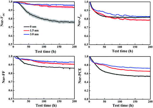
Fig. 7 depicts the evolution of VOC, JSC, FF and PCE of the P3HT:bis-PC61BM solar cells with different C60 layers aged at mpp with continuous light illumination. As can be seen here, the pristine P3HT:bis-PC61BM cells undergo a fast “burn-in” degradation over 200 h, with a fast VOC decay of 24%, JSC decay of 19% and FF decay of 14%. In contrast, P3HT:bis-PC61BM solar cells inserted with 3 nm of C60 layer show an overall 28% PCE degradation, with only 5% VOC decay, 17% JSC decay and 7% FF decay. Obviously, the insertion of the C60 layer greatly improves the stability of VOC and FF of P3HT:bis-PC61BM solar cells. This can be understood by the fact that the insertion of the C60 layer reduces the contact of P3HT and MoO3, resulting in the inhibition of their reaction and thus improving the stability of devices. These results not only confirm that the interface degradation is the main factor of VOC and FF decays of P3HT:bis-PC61BM solar cells, but also provide an effective way to improve the stability of VOC and FF of different types of polymer solar cells.
 |
| | Fig. 7 Evolution of VOC, JSC, FF and PCE of ITO/ZnO/P3HT:bis-PC61BM/C60 (0–3 nm)/MoO3/Al solar cells aged at mpp with continuous light illumination. | |
3.3.2 Stability improvement by piperazine doping.
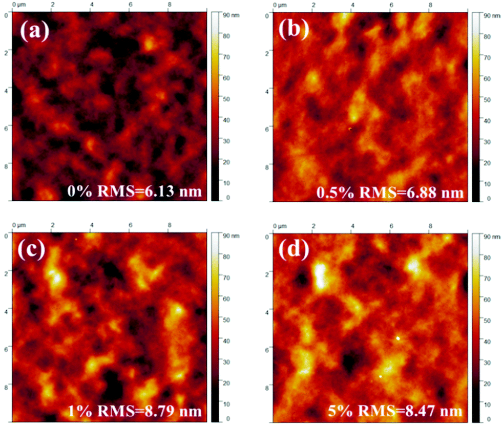
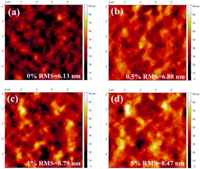
Although depositing a thin layer of C60 on the surface of the active layer can suppress the reaction between P3HT and MoO3, the complex evaporation process is not conducive to large-area printing preparation. Our previous works have demonstrated that piperazine is able to stabilize the P3HT:PC61BM cells through the blocking of the photodimerization process.23 Our latest results confirmed also that piperazine is able to form hydrogen bonds with fullerene molecules.38 It is supposed that doping the photoactive layer with piperazine might be able to tune the vertical phase separation of the photoactive layer owing to the volatility of piperazine and the capability of forming hydrogen bonding with fullerene molecules. We then fabricated piperazine doped P3HT:bis-PC61BM films, and checked the nanomorphology and surface component of these films. Fig. 8 shows the AFM images of the P3HT:bis-PC61BM films doped with different piperazine concentration. The root mean surface roughness (RMS) of these films is measured to be 6.13, 6.88, 8.79 and 8.47 nm for P3HT:bis-PC61BM blend films doped with 0%, 0.5%, 1% and 5% of piperazine, respectively, indicating that piperazine doping is able to tune the nanomorphology of the P3HT:bis-PC61BM film.
 |
| | Fig. 8 AFM images of P3HT:bis-PC61BM blend films with different concentrations of piperazine. | |
Then XPS characterization was performed to characterize the surface components of the P3HT:bis-PC61BM film with piperazine doping. Fig. S6 (ESI†) shows the XPS spectra of C 1s and S 2p of P3HT:bis-PC61BM blend films with different concentrations of piperazine. As seen here, the C 1s peak can be fitted into two components, corresponding to C–C at 284.78 eV and C–O at 285.91 eV,39 where the C–O signal can be assigned to the component of bis-PC61BM. Fig. 9 shows the fitted results of C–C and C–O. The C–O/C–C ratios for these films were calculated from the overall area ratio of C 1s(C–O) and C 1s(C–C) XPS signals, and the results are listed in Table 3. As seen here, doping the blend film with piperazine increases the C–O/C–C ratio from 0.27 to 0.29–0.30, suggesting slightly higher bis-PC61BM content after piperazine doping.
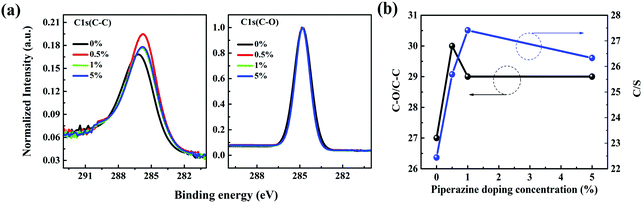 |
| | Fig. 9 Normalized XPS spectra of C 1s of P3HT:bis-PC61BM blend films with different concentrations (0–5%) of piperazine. | |
Table 3 C–O/C–C ratio, C/S ratio and bis-PC61BM/3-hexylthiophene molecular ratio determined by the deconvolution of C 1s and S 2p XPS spectra for P3HT:bis-PC61BM blend films with different piperazine doping concentrations
| Piperazine doping ratio (%) |
C–O/C–C |
C/S |
Bis-PC61BM/3-hexylthiophene ratio |
| 0 |
0.27 ± 0.011 |
22.44 ± 1.05 |
0.148 |
| 0.5 |
0.30 ± 0.017 |
25.69 ± 0.71 |
0.187 |
| 1 |
0.29 ± 0.016 |
27.41 ± 0.06 |
0.207 |
| 5 |
0.29 ± 0.003 |
26.33 ± 0.40 |
0.194 |
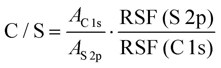
Similarly, the S 2p peak can also be fitted with two peaks centering at 164.98 and 163.73 eV, which can be attributed to the spin–orbit splitting doublet S 2p1/2 and S 2p3/2, respectively.40 The C/S ratios for these films are then calculated from the overall area ratio of C 1s and S 2p signals, taking into account the relative sensitivity factors (RSF):41
| |  | (1) |
where
AC1s and
AS2p are the overall area of C 1s and S 2p signals, respectively, RSF(S 2p) = 54.797 and RSF (C 1s) = 21.138 are determined by X-ray photoelectron spectroscopy. The molecular ratio of bis-PC
61BM to the 3-hexylthiophene unit (corresponding to P3HT content) on the surface of the photoactive layer is then calculated based on their molecular weights and C/S ratios. The results are summarized in
Table 3. The pristine composite film exhibits a C/S ratio of 22.44 and a bis-PC
61BM/3-hexylthiophene molecular ratio of 0.148. Not surprisingly, the piperazine doping significantly increases the C/S ratio (25.69–27.41) and the corresponding bis-PC
61BM/3-hexylthiophene molecular ratio (0.187–0.207), suggesting the increase of bis-PC
61BM content on the blend film surface, in good accordance with the increase of the above-mentioned C–O/C–C ratio.
UPS characterization of P3HT:bis-PC61BM blend films with different piperazine doping concentrations was performed further to investigate the migration of bis-PC61BM in the active layer, and the results are shown in Fig. S7 (ESI†). The results show that the HOMO of films increased from 5.75 to 5.90 eV after doping with piperazine. The HOMO levels of P3HT and bis-PC61BM were reported to be 4.77 eV26 and 6.10 eV,13 respectively. Therefore, the increase of the HOMO level on the surface of the film indicates that bis-PC61BM has undergone an upward migration in the active layer with the doping of piperazine.
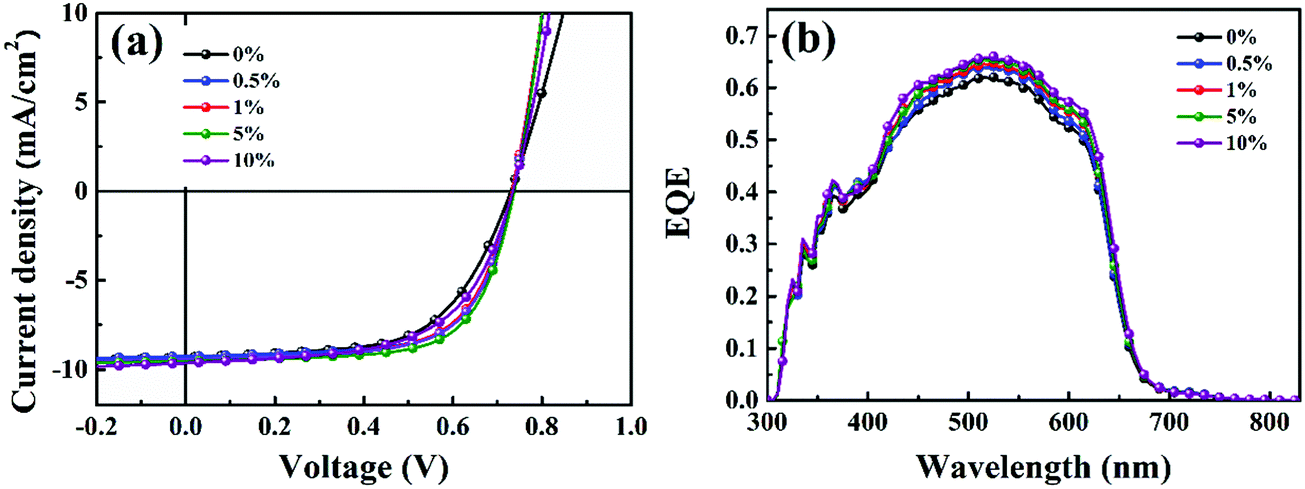
Then, the piperazine doped P3HT:bis-PC61BM solar cells were fabricated, and their photovoltaic performance and stability were tested. Fig. 10 shows the J–V curves and EQE spectra of P3HT:bis-PC61BM solar cells doped with piperazine, and the corresponding photovoltaic parameters are listed in Table 4. As can be seen here, the pristine P3HT:bis-PC61BM cells show a PCE of 4.07%. Doping piperazine into the photoactive layer significantly increases the PCE, and the highest PCE of 4.81% is achieved for the 5% piperazine doped cells. Such a performance enhancement is due to the large increase in the FF value and the slight increase in VOC and JSC values. In our previous work we confirmed that the intermolecular electron transfer between piperazine and fullerene molecules leads to n-doping of fullerene domains and consequently improves the electron mobility of the blend films,23 which should be the main reason for the JSC increase of the piperazine doped devices. However, the increased FF might be ascribed to the improvement of interface contact between the active layer and electrodes, which is confirmed by the AFM results (Fig. 8). It is worth highlighting that even at a high doping concentration of 10%, the device performance (4.59%) is still higher than that (4.09%) of the pristine cell. These results fully confirm that piperazine doping can also improve the device performance of P3HT:bis-PC61BM solar cells.
 |
| | Fig. 10
J–V curves (a) and EQE spectra (b) of P3HT:bis-PC61BM cells with piperazine doping concentrations of 0–10%. | |
Table 4 Photovoltaic parameters of P3HT:bis-PC61BM cells with piperazine doping concentrations of 0–10%
| Piperazine doping concentration (%) |
J
SC (mA cm2) |
V
OC (V) |
FF |
PCE (%) |
| 0 |
9.18 |
0.730 |
0.62 |
4.09 |
|
|
(9.10 ± 0.10) |
(0.728 ± 0.008) |
(0.61 ± 0.005) |
(4.07 ± 0.17) |
| 0.5 |
9.28 |
0.733 |
0.67 |
4.56 |
|
|
(9.23 ± 0.09) |
(0.731 ± 0.004) |
(0.66 ± 0.008) |
(4.45 ± 0.12) |
| 1 |
9.47 |
0.733 |
0.66 |
4.58 |
|
|
(9.40 ± 0.08) |
(0.729 ± 0.005) |
(0.65 ± 0.006) |
(4.45 ± 0.17) |
| 5 |
9.63 |
0.735 |
0.68 |
4.81 |
|
|
(9.59 ± 0.13) |
(0.732 ± 0.003) |
(0.67 ± 0.01) |
(4.71 ± 0.09) |
| 10 |
9.67 |
0.730 |
0.65 |
4.59 |
|
|
(9.59 ± 0.13) |
(0.727 ± 0.004) |
(0.64 ± 0.006) |
(4.46 ± 0.13) |
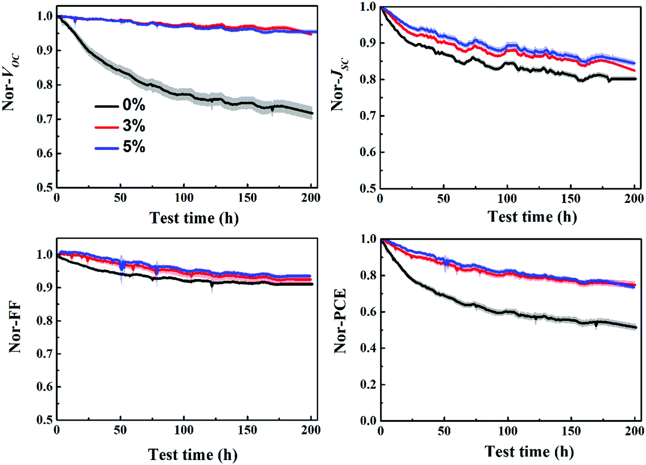
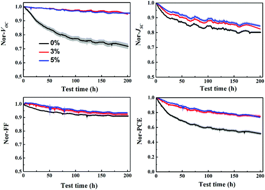
The stability of P3HT:bis-PC61BM solar cells with different concentrations of piperazine was further investigated, as shown in Fig. 11. The results show that the stability of piperazine doped solar cells increases significantly as expected, which is mainly due to the improved VOC and FF stability. When doped with 0.5% piperazine, P3HT:bis-PC61BM solar cells show almost no decay in VOC and FF, and slightly improved stability of JSC, which results in great stability improvement of device PCE. Given that bis-PC61BM is not prone to dimerization,20 the stability enhancement mechanism of piperazine doping is not dimerization inhibition, which can be confirmed by little improvement in JSC. Therefore, the stability improvement of P3HT:bis-PC61BM solar cells by piperazine doping is then ascribed to the increase of the bis-PC61BM component on the surface of active layers, which suppresses the interfacial photoreduction of MoO3.
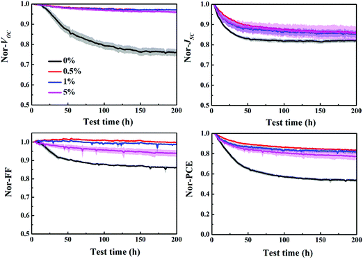 |
| | Fig. 11 Evolution of the VOC, JSC, FF and PCE of P3HT:bis-PC61BM cells with piperazine doping concentrations of 0–5% aged at mpp with continuous light illumination. | |
3.3.3 Suppressing Mo6+ reduction by piperazine doping and C60 insertion.
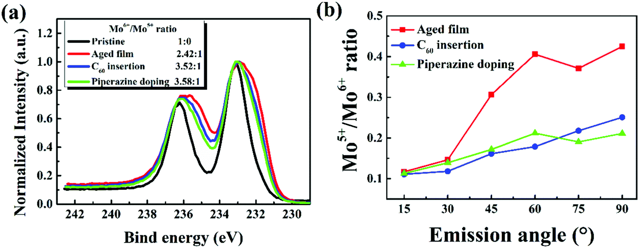
To further confirm that insertion of the C60 layer and doping of piperazine are able to suppress the reduction of MoO3, P3HT:bis-PC61BM/MoO3, P3HT:bis-PC61BM/C60/MoO3 and P3HT:bis-PC61BM:piperazine/MoO3 films were prepared and aged under light illumination for 5 h, and then checked with XPS (Fig. 5 and Fig. S8, ESI†). Fig. 12 displays the normalized XPS spectra of these films in comparison with the pristine reference film. As seen here, after light illumination, all these films show the broadening of XPS peaks, indicating the formation of Mo5+ during light illumination. The Mo6+/Mo5+ ratio of MoO3 films was determined by deconvolution of Mo6+ and Mo5+ XPS spectra, and the results are listed in Fig. 12. As seen here, both C60 insertion and piperazine doping increase the Mo6+/Mo5+ ratio (3.58:1 and 3.52:1) of MoO3 films in comparison with the aged bare P3HT:bis-PC61BM film (2.42:1), indicating that both methods inhibit the reduction of MoO3, again supporting the proposed degradation mechanism of this class of cells. Furthermore, ARXPS characterization of P3HT:bis-PC61BM/C60/MoO3 and P3HT:bis-PC61BM:piperazine/MoO3 films was also conducted, and the results are shown in Fig. S3(c) and (d) in the ESI.† Based on the ARXPS spectra, the Mo6+/Mo5+ ratios of the aged P3HT:bis-PC61BM/MoO3, P3HT:bis-PC61BM:piperazine/MoO3 and P3HT:bis-PC61BM/C60/MoO3 films were calculated. As seen from these figures, the P3HT:bis-PC61BM/MoO3 films with the C60 interlayer or doped with piperazine also showed broader XPS spectra with the increase of the detection depth, indicating the formation of Mo5+ at the buried interface after aging. The Mo5+/Mo6+ ratio calculated from the XPS spectrum is then plotted versus the ARXPS emission angle, and the results are shown in Fig. 12(b). As clearly shown here, the sample with the C60 interlayer or doped with piperazine showed a lower Mo5+/Mo6+ ratio at large emission angle, indicating that C60 insertion and piperazine doping have an inhibitory effect on the reduction of Mo6+. These results correspond very well to the stabilization effect of the C60 layer and the doping with piperazine in the solar cells (vide supra), confirming that the reduction of MoO3 by the p-type polymer should be one of the main reasons for the fast VOC and FF decays of the solar cells.
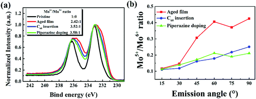 |
| | Fig. 12 XPS spectra of the Mo 3d core level peaks (a) and Mo6+/Mo5+ ratio plotted versus ARXPS emission angle (b) for the P3HT:bis-PC61BM/MoO3 films, P3HT:bis-PC61BM:piperazine/MoO3 and P3HT:bis-PC61BM/C60/MoO3 films after illumination for 5 h. | |
3.4 Stability improvement by piperazine doping in P3HT:ICBA solar cells
To confirm the generality of piperazine doping in improving the VOC and FF stability of polymer:fullerene bis-adduct solar cells, piperazine doped P3HT:ICBA solar cells were fabricated and tested. Fig. S9 (ESI†) shows the J–V and EQE spectra of the P3HT:ICBA cells with different piperazine doping concentrations and the photovoltaic performance data are listed in Table S2 (ESI†). Again, doping P3HT:ICBA with piperazine increases the device performance, and the highest PCE of 5.72% is achieved for the 5% piperazine doped cell, confirming the generality of piperazine doping in performance improvement. More importantly, piperazine doping can also improve the stability of P3HT:ICBA solar cells (Fig. 13), demonstrating the generality of VOC and FF degradation suppression effects of piperazine doping.
 |
| | Fig. 13 Evolution of the VOC, JSC, FF and PCE of P3HT:ICBA cells with piperazine doping concentrations of 0–5% aged at mpp with continuous light illumination. | |
4. Conclusions
In conclusion, the polymer:fullerene bis-adduct (bis-PC61BM and ICBA) based solar cells demonstrate a fast “burn-in” degradation under light illumination, where VOC and FF decays are quite significant to the overall performance degradation when compared to the PC61BM based cells. The recovery of VOC and FF of the cell by renewing the MoO3/Al electrode of the aged cell indicates that the interfacial degradation at the photoactive layer and MoO3 could be the main reason for VOC and FF decays. XPS analysis of the P3HT:bis-PC61BM/MoO3 films confirms the reduction of Mo6+ to Mo5+. Inserting a thin layer of C60 between the photoactive layer and MoO3 can suppress the reduction of Mo6+ and slower the VOC decay. Therefore a photo-induced reduction of Mo6+ to Mo5+ by P3HT is supposed to be the detailed mechanism for the VOC and FF decays of polymer:fullerene bis-adduct solar cells. In addition, piperazine doping within the P3HT:fullerene bis-adduct film increases the fullerene content on the surface of the photoactive layer, which consequently improved device stability. The current work reveals the interfacial degradation mechanism of PSCs, and provides effective solutions for stability improvement, which will guide in improving the stability of different types of polymer solar cells.
Conflicts of interest
There are no conflicts to declare.
Acknowledgements
The authors would like to acknowledge the financial support from the Ministry of Science and Technology of China (No. 2016YFA0200700), the Chinese Academy of Science (No. YJKYYQ20180029 and CAS-ITRI 2019010), the National Natural Science Foundation of China (61904121), the Youth Innovation Promotion Association, CAS (2019317), and the Natural Science Foundation of Shanxi Province (201801D221136). Thanks are also due to the support from the Suzhou Vacuum Interconnected Nanotechnology Workstation H005-2019 project.
Notes and references
- Y. Lin, B. Adilbekova, Y. Firdaus, E. Yengel, H. Faber, M. Sajjad, X. Zheng, E. Yarali, A. Seitkhan, O. M. Bakr, A. El-Labban, U. Schwingenschlögl, V. Tung, I. McCulloch, F. Laquai and T. D. Anthopoulos, Adv. Mater., 2019, 31, 1902965 CrossRef CAS PubMed.
- L. X. Meng, Y. M. Zhang, X. J. Wan, C. X. Li, X. Zhang, Y. B. Wang, X. Ke, Z. Xiao, L. M. Ding, R. X. Xia, H. L. Yip, Y. Cao and Y. S. Chen, Science, 2018, 361, 1094–1098 CrossRef CAS PubMed.
-
https://www.nrel.gov/pv/assets/pdfs/champion-module-efficiencies.20191104.pdf
.
- J. B. Zhao, Y. K. Li, G. F. Yang, K. Jiang, H. R. Lin, H. Ade, W. Ma and H. Yan, Nat. Energy, 2016, 1, 15027 CrossRef CAS.
- J. Huang, J. H. Carpenter, C. Z. Li, J. S. Yu, H. Ade and A. K. Y. Jen, Adv. Mater., 2016, 28, 967–974 CrossRef CAS PubMed.
- J. You, L. Dou, K. Yoshimura, T. Kato, K. Ohya, T. Moriarty, K. Emery, C.-C. Chen, J. Gao, G. Li and Y. Yang, Nat. Commun., 2013, 4, 1446 CrossRef PubMed.
- Y. Sun, M. Chang, L. Meng, X. Wan, H. Gao, Y. Zhang, K. Zhao, Z. Sun, C. Li, S. Liu, H. Wang, J. Liang and Y. Chen, Nat. Electron., 2019, 2, 513–520 CrossRef CAS.
- B. Fan, Z. Zeng, W. Zhong, L. Ying, D. Zhang, M. Li, F. Peng, N. Li, F. Huang and Y. Cao, ACS Energy Lett., 2019, 4, 2466–2472 CrossRef CAS.
- W. C. Zhao, S. S. Li, S. Q. Zhang, X. Y. Liu and J. H. Hou, Adv. Mater., 2017, 29, 1604059 CrossRef PubMed.
- M. T. Dang, L. Hirsch and G. Wantz, Adv. Mater., 2011, 23, 3597–3602 CrossRef CAS PubMed.
- S. H. Park, A. Roy, S. Beaupre, S. Cho, N. Coates, J. S. Moon, D. Moses, M. Leclerc, K. Lee and A. J. Heeger, Nat. Photonics, 2009, 3, 297–302 CrossRef CAS.
- S.-H. Liao, H.-J. Jhuo, Y.-S. Cheng and S.-A. Chen, Adv. Mater., 2013, 25, 4766–4771 CrossRef CAS PubMed.
- L. Ye, S. Zhang, D. Qian, Q. Wang and J. Hou, J. Phys. Chem. C, 2013, 117, 25360–25366 CrossRef CAS.
- M. Lenes, G. J. A. H. Wetzelaer, F. B. Kooistra, S. C. Veenstra, J. C. Hummelen and P. W. M. Blom, Adv. Mater., 2008, 20, 2116–2119 CrossRef CAS.
- H. Xin, S. Subramaniyan, T.-W. Kwon, S. Shoaee, J. R. Durrant and S. A. Jenekhe, Chem. Mater., 2012, 24, 1995–2001 CrossRef CAS.
- M. C. Scharber, D. Wuhlbacher, M. Koppe, P. Denk, C. Waldauf, A. J. Heeger and C. L. Brabec, Adv. Mater., 2006, 18, 789–794 CrossRef CAS.
- G. Dennler, M. C. Scharber and C. J. Brabec, Adv. Mater., 2009, 21, 1323–1338 CrossRef CAS.
- C. H. Peters, I. T. Sachs-Quintana, W. R. Mateker, T. Heumueller, J. Rivnay, R. Noriega, Z. M. Beiley, E. T. Hoke, A. Salleo and M. D. McGehee, Adv. Mater., 2012, 24, 663–668 CrossRef CAS PubMed.
- N. Li, J. D. Perea, T. Kassar, M. Richter, T. Heumueller, G. J. Matt, Y. Hou, N. S. Gueldal, H. W. Chen, S. Chen, S. Langner, M. Berlinghof, T. Unruh and C. J. Brabec, Nat. Commun., 2017, 8, 14541 CrossRef CAS PubMed.
- A. Distler, T. Sauermann, H.-J. Egelhaaf, S. Rodman, D. Waller, K.-S. Cheon, M. Lee and D. M. Guldi, Adv. Energy Mater., 2014, 4, 1300693 CrossRef.
- T. Heumueller, W. R. Mateker, A. Distler, U. F. Fritze, R. Cheacharoen, W. H. Nguyen, M. Biele, M. Salvador, M. von Delius, H. J. Egelhaaf, M. D. McGehee and C. J. Brabec, Energy Environ. Sci., 2016, 9, 247–256 RSC.
- L. P. Yan, J. D. Yi, Q. Chen, J. Y. Dou, Y. Z. Yang, X. G. Liu, L. W. Chen and C. Q. Ma, J. Mater. Chem. A, 2017, 5, 10010–10020 RSC.
- L. Yan, Y. Wang, J. Wei, G. Ji, H. Gu, Z. Li, J. Zhang, Q. Luo, Z. Wang, X. Liu, B. Xu, Z. Wei and C.-Q. Ma, J. Mater. Chem. A, 2019, 7, 7099–7108 RSC.
- A. Distler, T. Sauermann, H. J. Egelhaaf, S. Rodman, D. Waller, K. S. Cheon, M. Lee, N. Drolet and D. M. Guldi, Adv. Energy Mater., 2014, 4, 1300693 CrossRef.
- W. J. E. Beek, M. M. Wienk, M. Kemerink, X. N. Yang and R. A. J. Janssen, J. Phys. Chem. B, 2005, 109, 9505–9516 CrossRef CAS PubMed.
- N. Wu, Q. Luo, Z. M. Bao, J. Lin, Y. Q. Li and C. Q. Ma, Sol. Energy Mater. Sol. Cells, 2015, 141, 248–259 CrossRef CAS.
- T. Heumueller, T. M. Burke, W. R. Mateker, I. T. Sachs-Quintana, K. Vandewal, C. J. Brabec and M. D. McGehee, Adv. Energy Mater., 2015, 5, 1500111 CrossRef.
- T. Heumueller, W. R. Mateker, I. T. Sachs-Quintana, K. Vandewal, J. A. Bartelt, T. M. Burke, T. Ameri, C. J. Brabec and M. D. McGehee, Energy Environ. Sci., 2014, 7, 2974–2980 RSC.
- Y. J. He, H. Y. Chen, J. H. Hou and Y. F. Li, J. Am. Chem. Soc., 2010, 132, 1377–1382 CrossRef CAS PubMed.
- S. Y. Shao, J. Liu, J. Bergqvist, S. W. Shi, C. Veit, U. Wurfel, Z. Y. Xie and F. L. Zhang, Adv. Energy Mater., 2013, 3, 349–355 CrossRef CAS.
- Y. W. Zhu, Z. C. Yuan, W. Cui, Z. W. Wu, Q. J. Sun, S. D. Wang, Z. H. Kang and B. Q. Sun, J. Mater. Chem. A, 2014, 2, 1436–1442 RSC.
- F. X. Xie, W. C. H. Choy, C. D. Wang, X. C. Li, S. Q. Zhang and J. H. Hou, Adv. Mater., 2013, 25, 2051–2055 CrossRef CAS PubMed.
- Y. Yin, A. Sibley, J. S. Quinton, D. A. Lewis and G. G. Andersson, Adv. Funct. Mater., 2018, 28, 1802825 CrossRef.
- M. T. Greiner, M. G. Helander, W.-M. Tang, Z.-B. Wang, J. Qiu and Z.-H. Lu, Nat. Mater., 2012, 11, 76–81 CrossRef CAS PubMed.
- M. T. Greiner, L. Chai, M. G. Helander, W.-M. Tang and Z.-H. Lu, Adv. Funct. Mater., 2012, 22, 4557–4568 CrossRef CAS.
- Y. Yin, X. Pan, M. R. Andersson, D. A. Lewis and G. G. Andersson, ACS Appl. Energy Mater., 2020, 3, 366–376 CrossRef CAS.
- S. Engmann, A. J. Barito, E. G. Bittle, N. C. Giebink, L. J. Richter and D. J. Gundlach, Nat. Commun., 2019, 10, 227 CrossRef PubMed.
- Z. R. Li, J. K. Shan, L. P. Yan, H. M. Gu, Y. Lin, H. W. Tan and C. Q. Ma, ACS Appl. Mater. Interfaces, 2020, 12, 15472–15481 CrossRef CAS PubMed.
- B. Shamieh, S. Obuchovsky and G. L. Frey, J. Mater. Chem. C, 2016, 4, 1821–1828 RSC.
- G. M. Paternò, V. Robbiano, K. J. Fraser, C. Frost, V. García Sakai and F. Cacialli, Sci. Rep., 2017, 7, 41013 CrossRef PubMed.
- A. Kovtun, D. Jones, S. Dell'Elce, E. Treossi, A. Liscio and V. Palermo, Carbon, 2019, 143, 268–275 CrossRef CAS.
Footnote |
| † Electronic supplementary information (ESI) available. See DOI: 10.1039/d0ma00277a |
|
| This journal is © The Royal Society of Chemistry 2020 |
Click here to see how this site uses Cookies. View our privacy policy here. 
 Open Access Article
 This Open Access Article is licensed under a
  d,
Yongzhen
Yang
d,
Yongzhen
Yang