
 Open Access Article
 This Open Access Article is licensed under a
 Creative Commons Attribution 3.0 Unported Licence
Low temperature consolidation of hydroxyapatite-reduced graphene oxide nano-structured powders
Hassan
Nosrati
 a,
Rasoul
Sarraf-Mamoory
*a,
Reza
Zolfaghari Emameh
b,
Dang Quang Svend
Le
c,
Maria
Canillas Perez
d and
Cody Eric
Bünger
c
a,
Rasoul
Sarraf-Mamoory
*a,
Reza
Zolfaghari Emameh
b,
Dang Quang Svend
Le
c,
Maria
Canillas Perez
d and
Cody Eric
Bünger
c
aDepartment of Materials Engineering, Tarbiat Modares University, Tehran, Iran. E-mail: rsarrafm@modares.ac.ir
bDepartment of Energy and Environmental Biotechnology, National Institute of Genetic Engineering and Biotechnology (NIGEB), 14965/161, Tehran, Iran
cDepartment of Clinical Medicine, Aarhus University, Denmark
dInstituto de Cerámica y Vidrio, CSIC, Madrid, Spain
First published on 17th July 2020
Abstract
In this study, hydroxyapatite-reduced graphene oxide (HA-rGO) powders were first synthesized in situ using a hydrothermal method. These powders were then consolidated using a cold sintering method. The solvent used in this method was water + dimethylformamide + brushite which was added to the powders at different ratios. The sintered samples were then evaluated using X-ray diffraction, Fourier transform infrared spectroscopy, Raman spectroscopy, high-resolution transmission electron microscopy, and Vickers microindentation. The results of this study showed that the best conditions for the sintering of rGO-HA nanopowders were a temperature of 200 °C, a holding time of >30 min, and a pressure of 500 MPa. The best mechanical properties were achieved when the solvent content was considered to be 20 wt%. Crack deflection and graphene bridging were among the mechanisms that increased the fracture toughness of these nanocomposites. By adding 1.5% rGO, the fracture toughness of this nanocomposite (using the cold sintering method) was approximately equivalent to that of spark plasma sintered HA.
1 Introduction
Graphene-HA nanocomposites have received much attention in recent years. These types of nanocomposites have many uses as biomaterials, either as coatings on other materials or as bulk samples. Results from previous studies have shown that these two phases have strengthened each other's properties well.1–4 In graphene-HA nanocomposites, HA is the matrix phase. HA as a member of the calcium phosphate family has a hexagonal structure with a calcium-to-phosphate ratio of 1.67 and has a very similar chemical composition to bone. The biomaterial properties of HA, such as high compatibility with living bone tissues, scaffolding properties, biocompatibility, osteoconductivity, and bioactivity, have resulted in its wide use in biomedical fields.5–10 Therefore, various methods have been used to synthesize this material such as the combustion method,11 synthesis via solid-state reactions,12 electrochemical deposition,13 a sol–gel process,14,15 a hydrolysis method,16 a precipitation technique,17,18 synthesis via sputtering,19 multiple emulsion systems,20 biomimetic deposition of HA on GO,21 solvothermal, and hydrothermal processes.22,23 These methods have led to the synthesis of HA with different morphologies.24–29 But, despite all these properties, HA exhibits poor mechanical properties, including low fracture toughness, poor tensile strength, and weak wear resistance, leading to restrictions on the use of HA as a bone replacement implant.30–33It is necessary to improve the mechanical properties of HA with a reinforcing material. Among various materials used for this purpose, graphene has high potential due to its good reinforcing properties. Graphene sheets with a carbon atom thickness, a honeycomb structure, a high specific surface area (2630 m2 g−1), and unique mechanical properties play a reinforcing role in these nanocomposites.34–39 Apart from the excellent mechanical properties of graphene such as an elastic modulus of 1 TPa and a high fracture strength of 130 GPa, the good biocompatibility of this material has led to their consideration in biomedical applications such as drug delivery, orthopedics, and bioimaging.40–43 Published reports show that the addition of graphene and its derivatives (reduced graphene oxide and graphene nanoribbons) to HA, which is performed using various methods such as the hydrothermal process, has always improved the mechanical properties of HA.44–46
In some applications, such as implants, synthesized powders need to be made into a bulk shape. Different methods such as hot pressing and spark plasma sintering have been used to consolidate these types of powders.47,48 But, in most techniques, it is used at high temperatures. That high temperature also increases the cost of production, as well as the risk of material destruction. Recently, consolidation techniques at low temperatures have been greatly considered. This method, which is called cold sintering, is used at temperatures below 300 °C, with a pressure of 100 to 500 MPa. In the first instance, a liquid phase as a solvent in a very small amount is added to the interface between particles.49–51 A portion of the particle surface is dissolved in the liquid phase. The powders are then compressed under external pressure and the compression is facilitated by the presence of a liquid phase as a lubricant. Dissolution occurs in the interface between particles and the sharp edges of particles. It precipitates between particles and hollows. Finally, after applying the heat and pressure and removing the liquid phase, the particles are connected to each other. The important factors of the cold sintering process are powder materials, solvents, and physical parameters, but the solvent selection is more important. In some cases, additional heat treatment for annealing is used.52–58 So far, very few reports have been published on the cold sintering of hydroxyapatite containing powders.59–61
In this study, hybrid nanostructured powders were synthesized using a high-pressure hydrothermal method utilizing hydrogen gas injection to increase the reduction rate of GO. To investigate the final composite properties, a cold sintering method has been used. The sintered samples were subjected to a Vickers indentation technique for mechanical evaluation, X-ray diffraction (XRD), Raman spectroscopy, field emission scanning electron microscopy (FESEM), Fourier transform infrared spectroscopy (FTIR), and high-resolution transmission electron microscopy (HRTEM).
2 Experimental
The primary chemicals used in this study, along with their specifications, are listed in Table 1. The initial solution (S1) was first prepared (DMF + DI water with a volume ratio of 20![[thin space (1/6-em)]](https://www.rsc.org/images/entities/char_2009.gif) :80). DMF was considered for a better dispersion of GO in the solvent.35,45
:80). DMF was considered for a better dispersion of GO in the solvent.35,45
| Chemical | Company, purity |
|---|---|
| Graphene oxide (GO) (COxHy) | Abalonyx, 25 g L−1 DMF |
| Calcium nitrate tetrahydrate (Ca(NO3)2·4H2O) | Merck, >99% |
| Diammonium hydrogen phosphate ((NH4)2HPO4) | Merck, >99% |
| Ammonium solution (NH4OH) | Merck, 25% |
| Dimethyl formamide (DMF) ((CH3)2NC(O)H) | Sigma-Aldrich, >99.8% |
2.1 Synthesis of powders
Scheme 1 shows the synthesis process of the rGO-HA powders. The amount of rGO used in this study is 1.5% by weight because, according to previous studies,4 this amount has had the greatest effect on increasing the fracture toughness of rGO-HA nanocomposites (the approximate amount of rGO was estimated by trial and error). Given Scheme 1, the following steps were performed in order: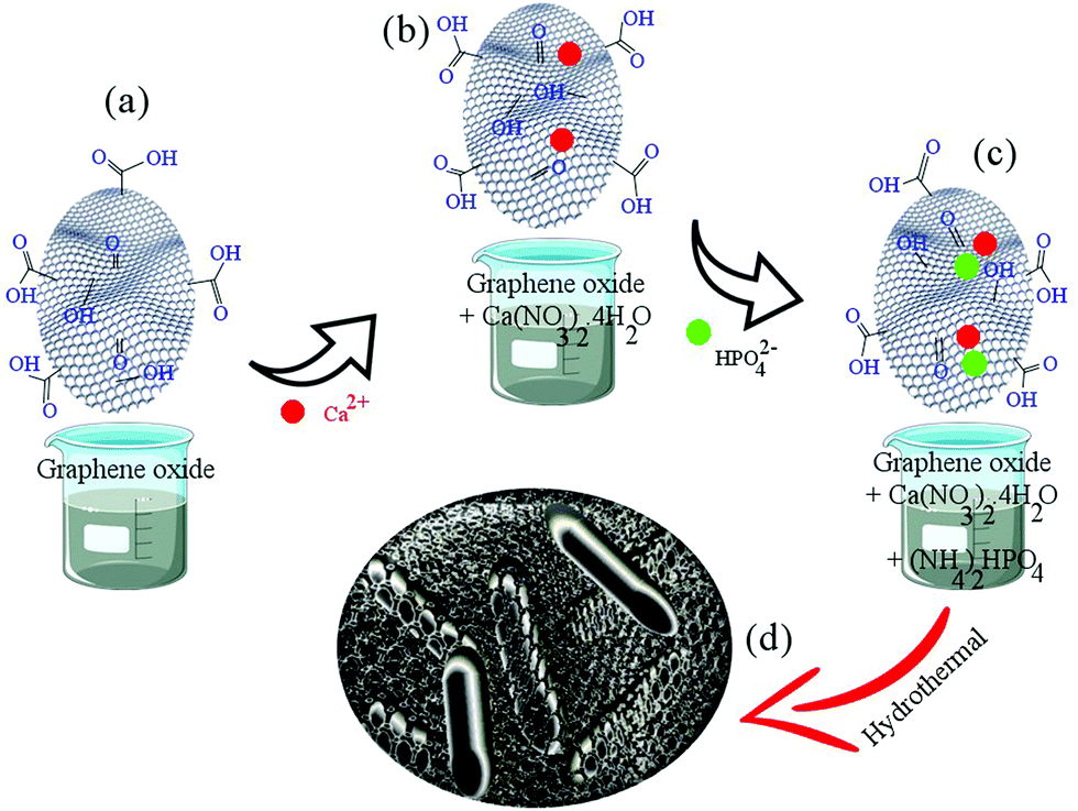 | ||
| Scheme 1 Synthesis process of rGO-HA powders. | ||
i. The solution containing Ca2+ (4.7 grams of calcium nitrate tetrahydrate in 120 mL of S1) was added dropwise to a 20 mL stirred suspension of GO (HA/1.5% rGO) with stirring continued for 1 h (Scheme 1a and b).
ii. The solution containing phosphate ions (1.56 g of diammonium hydrogen phosphate in 80 mL of S1) was added dropwise to the solution (Scheme 1c).
iii. The pH of the solution was adjusted to >10 with ammonium solution.
iv. The resulting solution was poured into a Teflon (PTFE) vessel and transferred to an autoclave. The hydrothermal process was carried out for 5 h at 180 °C via the injection of hydrogen gas at 10 bar (the volume of the PTFE container was 340 mL).
v. The powders were dried in an oven for 12 h at 60 °C.
vi. The resulting powders were consolidated after drying and ball milling (250 rpm, 12 h).
2.2 Consolidation of powders
Chart 1 shows the steps of consolidation. Fig. 1 shows the system used for the sintering and Vickers indentation evaluation of the samples. At the cold sintering stage, the mixture (M1) used consists of GO, brushite, and DMF. The mixture of brushite and GO was prepared similar to the powder synthesis step (Scheme 1c; at this stage of powder synthesis, a mixture of brushite and GO was synthesized). The use of brushite was due to the fact that this calcium phosphate is converted to HA under high pressure and temperature conditions.23 The amounts of GO-brushite powders were 5% by weight (DMF). The ratio of calcium to phosphate in this mixture was considered to be 1.67. A cold sintering method was chosen for sintering these powders (Chart 1). To form the ceramic pellets, 10 (I), 15 (II), and 20 (III) wt% of M1 were, respectively, mixed with 3 g of the rGO-HA powders using a pestle and mortar. The mixture was then placed in a die (30 mm in diameter) and subject to a uniaxial pressure of 500 MPa (Fig. 1a). The die was held at room temperature (approximately 25 °C) for 10 min and then heated to 200 °C at a rate of 5 °C min−1. The holding time of the samples at 200 °C was 60 min. The as-prepared ceramic samples (approximately 30 mm in diameter and ∼2 mm in thickness) were dried at 200 °C overnight to remove the possible residual solvent in an argon atmosphere. For comparison, a sample of pure HA (0% of rGO) was prepared under similar conditions with 20% of M1.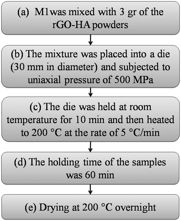 | ||
| Chart 1 Consolidation steps. | ||
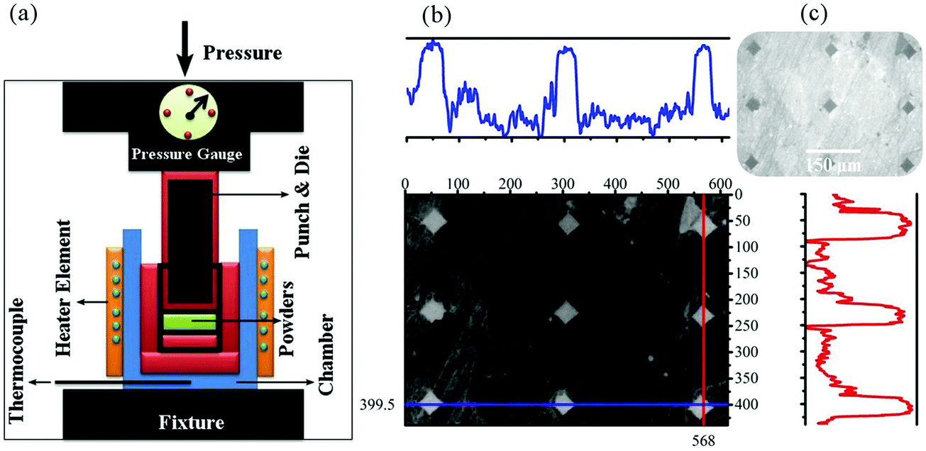 | ||
| Fig. 1 (a) Schematic image of the cold sintering system and (b) Vickers indentation evaluation of the cold sintered samples. | ||
Before performing the above steps, considering the study sources, the temperature, time and pressure applied were first evaluated and the best conditions were considered for cold sintering with respect to the relative density obtained for each sample (described later).
The Archimedes method was used to calculate the relative density of the sintered samples (ASTM C373-88).47 A Micrometrics AutoPore III 9410 porosimeter (mercury porosimetry recorded in the 5 × 10⁻³ to 3 × 102 μm range) was used to evaluate the distribution of porosity.
2.3 Vickers indentation
Instrumented microindentation experiments were conducted on the polished surfaces of samples using a GrindoSonic tester with a Vickers tip at a maximum load of 1 N (a ramp dwell time of 10 s). Nine tests (Fig. 1b) were performed at different locations of each sample. Elastic modulus and hardness were calculated from the load–displacement curves (Fig. 1c) using the Oliver–Pharr method.62 The modified Antis method was used to evaluate the fracture toughness (K1C) of the samples (eqn (1)):63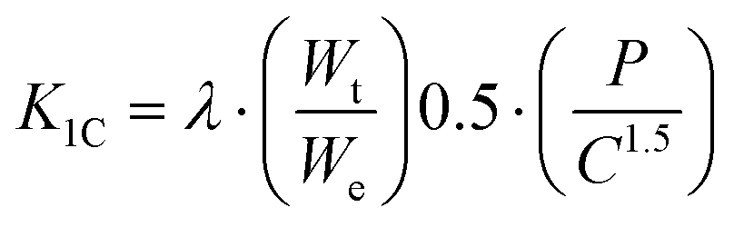 | (1) |
2.4 Characterization techniques
XRD (X’Pert Pro, PANalytical Co.) was used to determine the phase constituents of the samples, containing a detector with Cu Kα radiation (λ = 1.5406 Å, 40 kV, 40 mA) and a 2theta scanning range from 10° up to 80° in steps of 0.02°.FESEM (Hitachi S4700 equipped with energy dispersive X-ray spectroscopy) and a portable scanning electron microscope (SEM, TM-1000) were used to observe the morphology of the samples (mounted in an adhesive carbon film and Au coated by sputtering for its observation).
FTIR (VERTEX 70, Bruker Corp.) was used to identify the functional groups of the samples (a resolution of 4 cm−1, a scan number of 8, a spectral region from 400 to 4000 cm−1 using 2 cm−1 steps). The samples were prepared and mixed with potassium bromide (KBr) in a concentration of 1 mg powdered samples and 300 mg KBr. The mixture was pressed into discs with a thickness of 1 mm by applying a pressure of 200 MPa. The spectra were collected at room temperature (25 °C) and 60% relative humidity.
Raman spectroscopy (Renishaw inVia spectrometer) was used in the range of 300–3500 cm−1, recording 5 times for 10 seconds of each accumulation, with a green laser line at a wavelength of 532 nm in a backscattering configuration using a microscope with a 100× objective, a 100% power, and an acquisition time of 10 s, which had been excited from an argon ion laser.
HRTEM (TALOS F200A with a twin lens system, an X-FEG electron source, a Ceta 16M camera and a super-X EDS detector) was used to observe the atomic structure of the samples and for spatially resolved elemental analysis, with a spatial resolution higher than 2 nm. To study the atomic structure, fast Fourier transform (FFT) and inverse fast Fourier transform (IFFT) analyses were used. The ImageJ 1.52d and Diamond 3.2 software were used in this study.
3 Results and discussion
Fig. 2 shows the FESEM image of the rGO-HA nanopowders and the TEM images of the rGO-HA nanopowders and HA nanorods synthesized via the hydrothermal method. As shown in the FESEM image (Fig. 2a), the HA particles are attached to the rGO surfaces, edges and between the graphene sheets while the rGO sheets are folded and wrinkled. In some areas, HA particles have been agglomerated. The TEM image (Fig. 2b) also shows the presence of rGO and HA. It is clear that the morphology of the HA particles is nanorod shaped (Fig. 2c). These nanorods are less than 50 nanometers in diameter while showing longitudinal variations. The growth direction of the nanorods is in the C-axis.64–66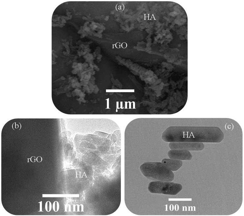 | ||
| Fig. 2 (a) FESEM image of rGO-HA nanopowders (1.5% rGO) synthesized by the hydrothermal method and (b and c) TEM images of rGO-HA nanopowders (1.5% rGO) and HA nanorods. | ||
Fig. 3 shows the EDS analysis of rGO-HA nanopowders (1.5% rGO) synthesized by the hydrothermal method, the high-angle annular dark-field (HAADF) image of rGO-HA nanopowders, and the elemental analysis of rGO-HA nanopowders. These findings showed that trace elements are present in the final synthesized powder and are distributed homogeneously. Previous studies have included complementary analyses that confirm the calcium to phosphate ratio of 1.67.64–66
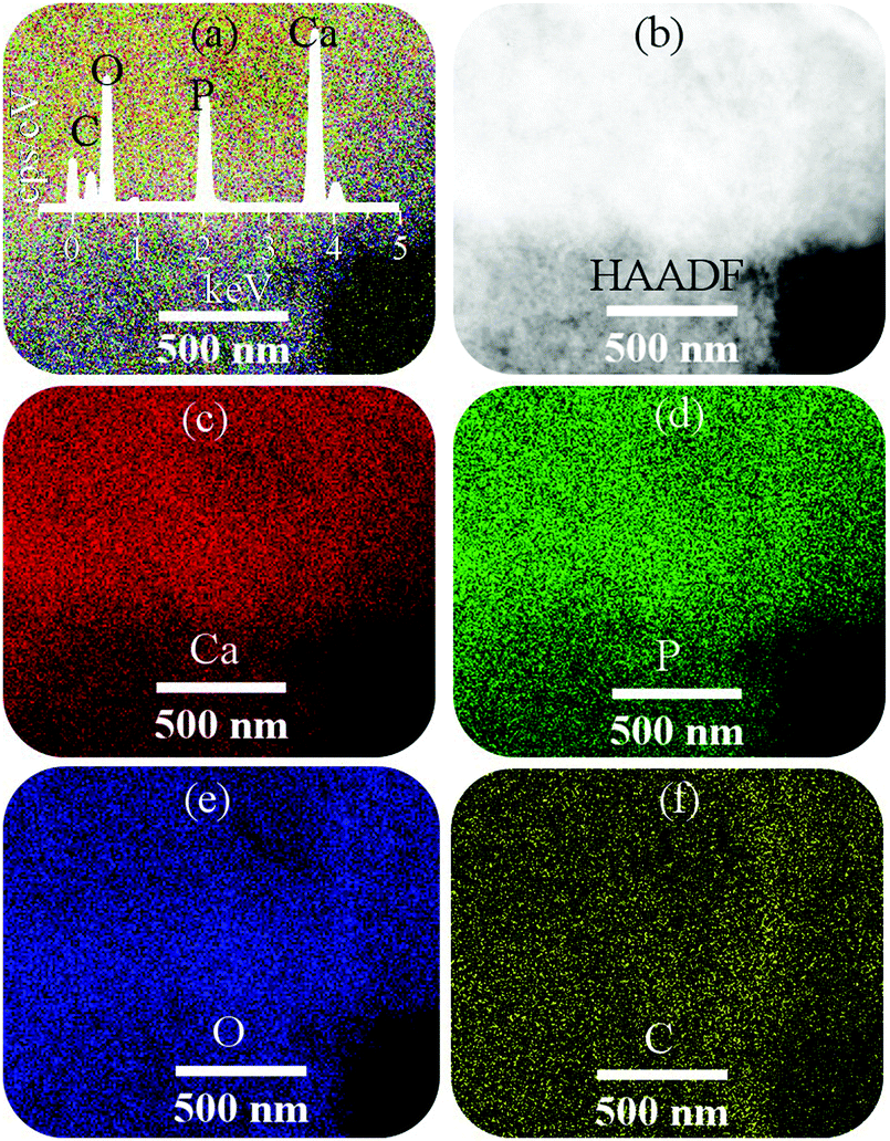 | ||
| Fig. 3 (a) EDS analysis of rGO-HA nanopowders (1.5% rGO) synthesized by the hydrothermal method, (b) HAADF image of rGO-HA nanopowders, and (c–f) elemental analysis of rGO-HA nanopowders. | ||
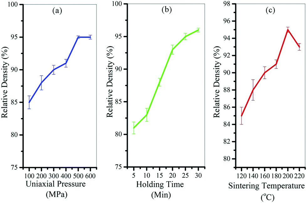
Fig. 4 shows the results of the designed experiments to find the best cold sintering conditions. As can be seen from the graphs, the best temperature was 200 °C (Fig. 4c), the best holding time was 30 minutes (Fig. 4b), and the best applied pressure was 500 MPa (Fig. 4a) to achieve the highest relative density. It should be noted that the solvent content in these samples was considered to be 20% by weight.
 | ||
| Fig. 4 Results of the designed experiments to find the best (a) uniaxial pressure, (b) holding time, and (c) cold sintering temperature. | ||
Fig. 5 shows the XRD patterns of the consolidated HA and rGO-HA nanocomposites for 10 (I), 15 (II), and 20 (III) wt% solvent along with the crystal structure of HA. According to the XRD pattern of the samples (Fig. 5a), full conformity is achieved between the obtained peaks and the reference standard of pure HA (JCPDS 09-0432). Accordingly, the XRD pattern of the rGO-HA nanocomposites is quite similar to that of pure HA with high purity and a hexagonal structure. According to studies, the famous GO peak is located at 2theta ≈ 10. After the reduction of GO to rGO, this peak disappears and a new one appears at 2theta ≈ 26. Because of the amorphous structure of rGO, this peak is much weaker and wider than the HA (002) peak. Therefore, the rGO peak is covered by the HA (002) peak which is highly intensified due to its high crystallinity. Table 2 shows the specification of the main HA scatter planes obtained. According to the XRD pattern the (002), (211), and (300) planes are the main growth planes in HA crystals where the (002) and (300) planes are perpendicular (Fig. 5b). Increasing the amount of the solvent has increased the intensity of the peaks in some directions and decreased it in some directions. In the direction of the (002) plane, increasing the amount of the solvent has reduced the peak intensity, but in the case of the (211) and (300) planes the peak intensity has increased. Also, the peaks have shifted slightly to the left, which is probably due to the increased pressure from the solvent steam. Comparing the obtained peaks, it is clear that the presence of rGO did not have much effect on the peak shift.45,47,65,66
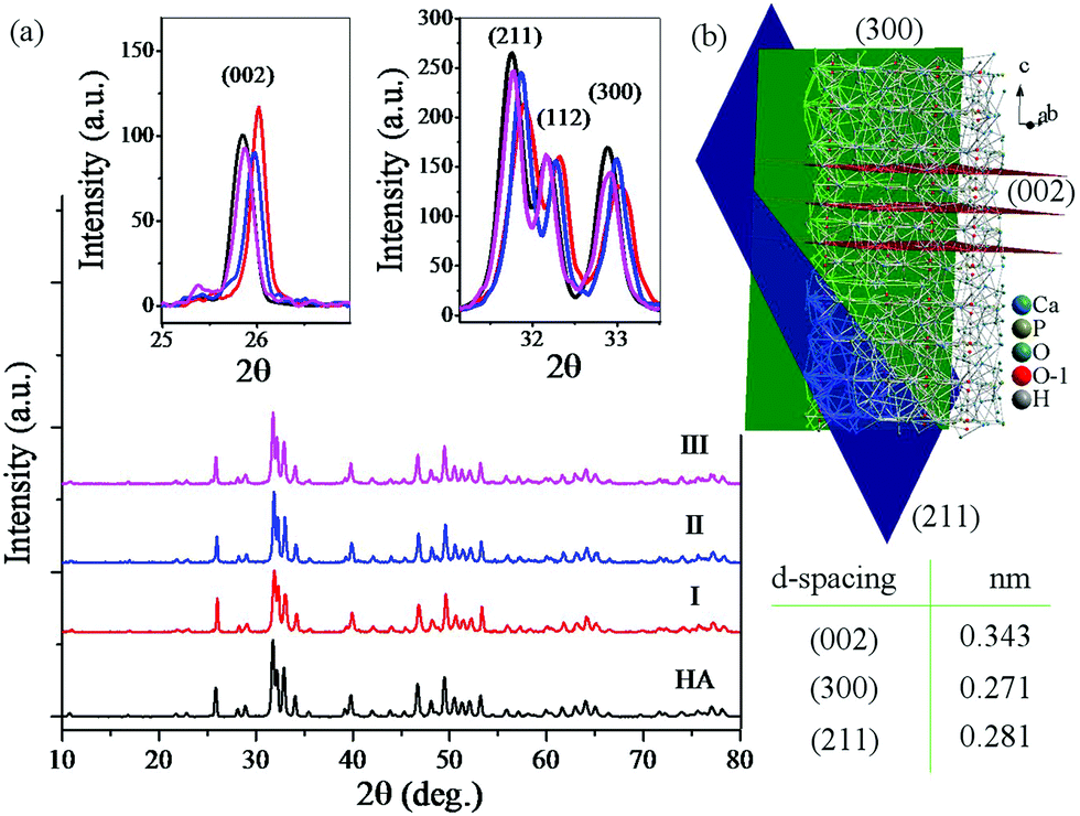 | ||
| Fig. 5 (a) XRD patterns of consolidated rGO-HA nanocomposites for 10 (I), 15 (II), and 20 (III) wt% solvent and pure HA; (b) crystal structure of HA. | ||
| (hkl) | (002) | (211) | (300) |
| d-Spacing (nm) | 0.343 | 0.281 | 0.271 |
| 2theta (deg) | 26 | 32 | 33 |
Fig. 6 shows the Raman spectra and the FTIR analysis results for consolidated samples. Raman spectroscopy has been performed to confirm the presence of rGO (Fig. 6a). The peaks obtained for nanocomposite samples are almost identical and confirm the presence of graphene sheets. In all spectra, the peaks located at 962 cm−1 are related to the P–O symmetric stretching (v1 PO43−) in HA. The peaks located at 1350, 1600, and 2700 cm−1 are related to the D bond (symmetric oscillations of the A1g of carbon atoms with the sp3 hybrid), G bond (shaking of the E2g of the carbon atom phonon with the sp2 hybrid), and 2D peak (related to the number of layers of the graphene sheets) in rGO. The rGO-related Raman signals in these spectra are much clearer than the HA signals, although its weight percent in the powders is much lower. The D and G peaks in the rGO have not had any displacement in the Raman spectra, indicating that the rGO-HA nanocomposites have been successfully synthesized.65,66 The FTIR analysis results reveal that the nanocomposites contain rGO and HA (Fig. 6b). The peaks located at 565 cm−1 (P–O bending) and 925, 1035, and 1095 cm−1 (P–O(H) stretching vibration) are related to HA. The peaks located at 1055 cm−1 (C–O stretching vibration), 1230 cm−1 (C–OH stretching vibration), 1395 cm−1 (C–O–H deformation vibration), 1620 cm−1 (C![[double bond, length as m-dash]](https://www.rsc.org/images/entities/char_e001.gif) C stretching vibration), and 1730 cm−1 (CO stretching vibration) are related to GO. The peaks located at 3400–3500 cm−1 (O–H stretching vibration) are related to GO and HA. By comparing the FTIR patterns, it can be seen that the peaks obtained for the nanocomposites correspond to the pure HA peaks. These findings suggest that GO peaks have shifted upwards. The most significantly changed peaks are the oxygen-containing functional groups on the GO surface (C–O, C–O–H, CO) that have shifted upwards due to the reduction of GO. However, there may still be oxide groups whose peaks are covered with the HA peaks.44,45 By juxtaposing the findings of Raman spectroscopy and FTIR analyses, it is clear that graphene sheets (in the form of rGO) are present in all nanocomposites.
C stretching vibration), and 1730 cm−1 (CO stretching vibration) are related to GO. The peaks located at 3400–3500 cm−1 (O–H stretching vibration) are related to GO and HA. By comparing the FTIR patterns, it can be seen that the peaks obtained for the nanocomposites correspond to the pure HA peaks. These findings suggest that GO peaks have shifted upwards. The most significantly changed peaks are the oxygen-containing functional groups on the GO surface (C–O, C–O–H, CO) that have shifted upwards due to the reduction of GO. However, there may still be oxide groups whose peaks are covered with the HA peaks.44,45 By juxtaposing the findings of Raman spectroscopy and FTIR analyses, it is clear that graphene sheets (in the form of rGO) are present in all nanocomposites.
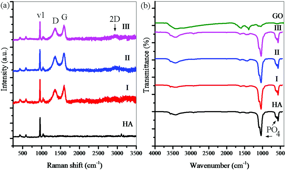 | ||
| Fig. 6 (a) Raman spectroscopy and (b) FTIR analysis for consolidated samples for 10 (I), 15 (II), and 20 (III) wt% solvent and pure HA. | ||
Fig. 7 shows the FESEM images of the fracture surfaces of samples after cold sintering and the mechanism of cold sintering and post-drying based on the experimental results. FESEM images show the presence of graphene in three dimensions. The graphene layers are assembled together (Fig. 7a) so that the HA particles are placed between them (Fig. 7b and c). As it is known, the presence of this three-dimensional structure causes incomplete compression during sintering and, in any case, increases porosity and it is expected that by increasing the amount of rGO the porosity will increase equally as previously this issue was characterized by relative density. The presence of these porosities may in part deteriorate the mechanical properties because they are localized to crack nucleation and to focus stresses, but according to previous studies the presence of these porosities can increase the osteoconductivity of these materials. According to Fig. 7(d–f), the powders were first uniformly wetted using the solvent and mixed with brushite and GO (Fig. 7d). Under uniaxial pressure, during the hydrothermal reaction brushite and GO were redistributed and filled into the interspaces between the rGO-HA particles, thereby aiding the rearrangement of the particles. When the temperature was increased up to 200 °C (Fig. 7e), brushite dissolved in water and DMF to form amorphous complexes. Because the temperature is higher than the boiling point of the solvent, the water and DMF in the samples continuously evaporated until they were exhausted. The amorphous phase was filled into the interspaces between the particles, and dense crystal/amorphous ceramics were obtained. The amorphous phase transformed into the crystalline phase during the annealing process (Fig. 7f). The grains grew gradually, and the interspaces were filled further.
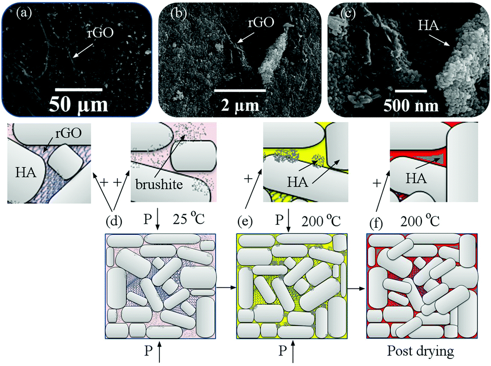 | ||
| Fig. 7 (a–c) FESEM images of the fracture surfaces of samples after cold sintering for sample (III) and (d–f) the mechanism of cold sintering and post-drying based on the experimental results. | ||
Fig. 8 shows the FESEM images of the pores in the HA and rGO-HA samples (20% solvent), the pore size distribution, and the relative density of the samples. The FESEM images show that the presence of rGO has caused larger pores (Fig. 8a and b). The pore size distribution diagram obtained using the Washburn equation67 (Fig. 8c) shows that the size of the porosity in the rGO-HA sample has increased. The total porosities were 3.5% for HA and 5% for the rGO-HA nanocomposite. Also, densitometry results (Fig. 8d) showed that the highest relative density was related to sample (III) with a 20% solution.
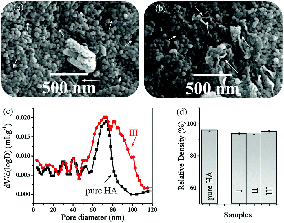 | ||
| Fig. 8 (a) FESEM images of the pores in the HA sample (20% solvent), (b) FESEM images of the pores in the rGO-HA sample (20% solvent), (c) pore size distribution, and (d) the relative density of the samples. | ||
Fig. 9 shows the force–displacement diagrams of the sintered samples. To compare the effect of the solvent percentage during the cold sintering process on the final properties of the nanocomposites, all samples were subjected to a Vickers test. As the curves show (Fig. 9a) the contact depth for sample (I) is greater than those for samples (II) and (III). In other words, more force is needed to achieve a constant contact depth in (II) and (III). This conclusion is also valid for (III) compared to (II). Considering the same conditions for the preparation of samples, it is likely that another mechanism including a higher degree of GO reduction or higher crystallinity, and more accurate stoichiometry of HA is most likely responsible for this phenomenon. Also, according to these diagrams, the elastic work in (I) is greater than that in the other samples. Also, the plastic work is slightly higher in (I), but with a smaller ratio, which is obtained from the surface below the curves. In these diagrams, the transition to the left means the improvement of the mechanical properties. In Fig. 9b, the force–displacement curve shows that the Vickers indenter has hit a hole in its path. The part shown with the arrow shows the contact depth where the cavity is located. These changes are more evident in samples with high porosity. In some curves, these changes appear several times. These cases involve some errors in the calculations. The indentation analysis results (Table 3) show that the hardness and Young's modulus values of samples (II) and (III) are higher than those of (I). Also, (III) showed better mechanical properties compared with (II). The reason for this improvement in the mechanical properties should be examined from two perspectives. First, increasing the hydrothermal pressure increases the crystallinity of the primary powder and improves the properties of HA, and second the presence of more hydrogen gas increases the reduction degree of GO and improves the mechanical properties of the graphene sheets.45,47 The fracture toughness of this nanocomposite (III, by the cold sintering method) was approximately equivalent to that of spark plasma sintered HA.68
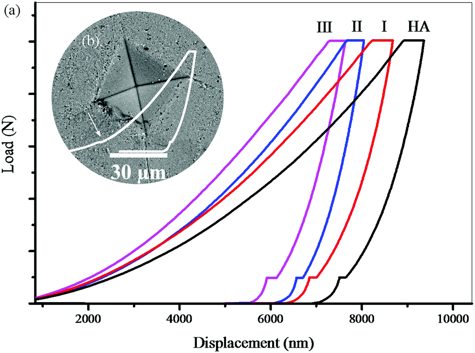 | ||
| Fig. 9 (a) Force–displacement diagrams of the sintered samples and (b) indentation affected zone. | ||
| Sample | Hardness (GPa) | Elastic modulus (GPa) | Fracture toughness (MPa m0.5) |
|---|---|---|---|
| HA | 2.5 ± 0.5 | 58 ± 6.4 | 0.41 ± 0.13 |
| (I) | 3.1 ± 0.4 | 79.5 ± 5.7 | 0.85 ± 0.11 |
| (II) | 3.7 ± 0.2 | 87.2 ± 4.6 | 0.97 ± 0.09 |
| (III) | 4.3 ± 0.3 | 95.7 ± 5.2 | 1.12 ± 0.03 |
Fig. 10 shows the FESEM images of the cracks formed during the mechanical analysis on the sintered samples. In these images, crack bridging and crack deflection are shown. Graphene sheets have increased the fracture toughness of the samples via these mechanisms. The pull out energy of graphene is much higher than the energy needed to pull out HA from each other because graphene sheets have a higher specific surface.45
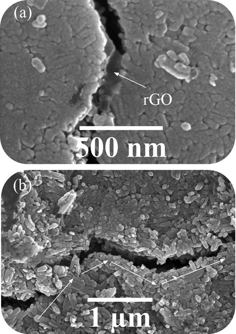 | ||
| Fig. 10 FESEM images of cracks formed during the mechanical analysis on sintered samples (III) with a 20% solvent. | ||
Fig. 11 shows the interface analysis between the two phases after consolidation. In this figure, HA, graphene sheets, and three areas identified for the analysis are shown. Fig. 11a shows the HA and rGO phases together. From Fig. 11b, the d-spacing of graphene sheets is 0.34 nm, which shows that GO is well reduced. In Fig. 11c, the d-spacing confirms the growth of the (211) plane in HA. Fig. 11d shows that the two phases are well connected. Previous studies have confirmed that there is a coherent interface between the two phases of HA and rGO.4,69,70
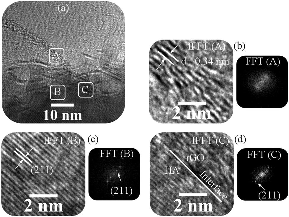 | ||
| Fig. 11 Interface analysis between the two phases after consolidation for sample (III), (a) HRTEM image of the consolidated sample, (b) FFT and IFFT analyses of the A area, (c) FFT and IFFT analyses of the B area, and (d) FFT and IFFT analyses of the C area. | ||
4 Conclusions
The results of this study showed that the best conditions for the sintering of rGO-HA nanopowders were a temperature of 200 °C, a holding time of >30 min, and a pressure of 500 MPa. The best mechanical properties were achieved when the solvent content was considered to be 20 wt%. By increasing the amount of the solvent up to 20 wt%, the hardness, elastic modulus and fracture toughness of rGO-HA nanocomposites reached values of 4.3 ± 0.3 GPa, 95.7 ± 5.2 GPa, and 1.12 ± 0.03 MPa m0.5, respectively. By adding 1.5% rGO, the fracture toughness of this nanocomposite (by the cold sintering method) was approximately equivalent to that of spark plasma sintered HA. The interface between the two phases in this nanocomposite was coherent. Crack deflection and graphene bridging were among the mechanisms that increased the fracture toughness of these nanocomposites.Conflicts of interest
There are no conflicts to declare.References
- H. Zanin, E. Saito, F. R. Marciano, H. J. Ceragioli, A. E. C. Granato, M. Porcionattod and A. O. Lobo, Fast preparation of nano-hydroxyapatite/superhydrophilic reduced graphene oxide composites for bioactive applications, J. Mater. Chem. B, 2013, 1, 4947–4955, 10.1039/C3TB20550A.
- N. Murugan, M. Chozhanathmisra, S. Sathishkumar, P. Karthikeyan and R. Rajavel, Corrosion and biodegradability evaluation of strontium substituted hydroxyapatite coating on surface treated AZ91 Mg alloy for biomedical application, International Journal of Pharmacy and Biological Sciences, 2016, 6(3), 184–190, DOI:10.21276/ijpbs.2016.6.3.21.
- I. Iacoboni, F. Perrozzi, L. Macera, G. Taglieri, L. Ottaviano and G. Fioravanti, In situ syntheses of hydroxyapatite-grafted graphene oxide composites, J. Biomed. Mater. Res., 2019, 107A, 2026–2039, DOI:10.1002/jbm.a.36716.
- H. Nosrati, R. Sarraf-Mamoory, D. Q. S. Le and C. E. Bünger, Enhanced fracture toughness of three dimensional graphene- hydroxyapatite nanocomposites by employing the Taguchi method, Composites, Part B, 2020, 190, 107928, DOI:10.1016/j.compositesb.2020.107928.
- M. Iafisco, M. Di Foggia, S. Bonora, M. Prat and N. Roveri, Adsorption and spectroscopic characterization of lactoferrin on hydroxyapatite nanocrystals, Dalton Trans., 2011, 40, 820–827, 10.1039/C0DT00714E.
- J. H. Lee, Y. C. Shin, S.-M. Lee, O. S. Jin, S. H. Kang, S. W. Hong, C.-M. Jeong, J. B. Huh and D.-W. Han, Enhanced Osteogenesis by Reduced Graphene Oxide/Hydroxyapatite Nanocomposites, Sci. Rep., 2015, 5, 1–13, DOI:10.1038/srep18833.
- J. Terra, G. B. Gonzalez, A. M. Rossi, J. G. Eon and D. E. Ellis, Theoretical and experimental studies of substitution of cadmium into hydroxyapatite, Phys. Chem. Chem. Phys., 2010, 12, 15490–15500, 10.1039/C0CP01032D.
- H. L. Jang, G. B. Zheng, J. Park, H. D. Kim, H.-R. Baek, H. K. Lee, K. Lee, H. N. Han, C.-K. Lee, N. S. Hwang, J. H. Lee and K. T. Nam, In Vitro and In Vivo Evaluation of Whitlockite Biocompatibility: Comparative Study with Hydroxyapatite and β-Tricalcium Phosphate, Advanced Healthcare, Materials, 2016, 5(1), 128–136, DOI:10.1002/adhm.201400824.
- M. Ding, N. Sahebgharani, F. Musharavati, F. Jaber, E. Zalnezhad and G. H. Yoon, Synthesis and properties of HA/ZnO/CNT nanocomposite, Ceram. Int., 2018, 44, 7746–7753, DOI:10.1016/j.ceramint.2018.01.203.
- H. Tavassoli, J. Javadpour, M. Taheri, M. Mehrjou, N. Koushki, F. Arianpour, M. Majidi, J. Izadi-Mobarakeh, B. Negahdari, P. Chan, M. E. Warkiani and S. Bonakdar, Incorporation of Nanoalumina Improves Mechanical Properties and Osteogenesis of Hydroxyapatite Bioceramics, ACS Biomater. Sci. Eng., 2018, 4(4), 1324–1336, DOI:10.1021/acsbiomaterials.7b00754.
- M. Canillas, R. Rivero, R. García-Carrodeguas, F. Barba and M. A. Rodríguez, Processing of hydroxyapatite obtained by combustion synthesis, Boletín de la Sociedad Española de Cerámica y Vidrio, 56(5) (2017) 237-242, 10.1016/j.bsecv.2017.05.002.
- X. Guo, H. Yan, S. Zhao, L. Zhang, Y. Li and X. Liang, Effect of calcining temperature on particle size of hydroxyapatite synthesized by solid-state reaction at room temperature, Adv. Powder Technol., 2013, 4(6), 1034–1038, DOI:10.1016/j.apt.2013.03.002.
- M. Shikhanzadeh, Direct formation of nanophase hydroxyapatite on cathodically polarized electrodes, J. Mater. Sci.: Mater. Med., 1998, 9, 67–72, DOI:10.1023/A:1008838813120.
- A. Jillavenkatesa and R. A. Condrate Sr., Sol–gel processing of hydroxyapatite, J. Mater. Sci., 1998, 33, 4111–4119, DOI:10.1023/A:1004436732282.
- T. A. Kuriakosea, S. N. Kalkura, M. Palanichami, D. Arivuoli, K. Dierks, G. Bocelli and C. Betzel, Synthesis of stoichiometric nano crystalline hydroxyapatite by ethanol-based sol–gel technique at low temperature, J. Cryst. Grow., 2004, 263(1–4), 517–523, DOI:10.1016/j.jcrysgro.2003.11.057.
- O. V. Sinitsyna, A. G. Veresov, E. S. Kovaleva, Y. V. Kolen’ko, V. L. Putlyaev and Y. D. Tretyakov, Synthesis of hydroxyapatite by hydrolysis of α-Ca3(PO4)2, Russ. Chem. Bull., 2005, 54(1), 79–86, DOI:10.1007/s11172-005-0220-9.
- C. Liu, Y. Huang, W. Shen and J. Cui, Kinetics of hydroxyapatite precipitation at pH 10 to 11, Biomaterials, 2000, 22(4), 301–306, DOI:10.1016/S0142-9612(00)00166-6.
- A. H. Ahmadi, H. Nosrati and R. Sarraf-Mamoory, Decreasing β-three calcium phosphate particle size using graphite as nucleation sites and diethylene glycol as a chemical additive, J. Bioengineering Res., 2019, 1(4), 50–58, DOI:10.22034/jbr.2019.211371.1016.
- K. Yamashita, T. Arashi, K. Kitagaki, S. Yamada and T. Umegaki, Preparation of apatite thin films through rfsputtering from calcium phosphate glasses, J. Am. Ceram. Soc., 1994, 77(9), 2401–2407, DOI:10.1111/j.1151-2916.1994.tb04611.x.
- I. Kimura, Synthesis of hydroxyapatite by interfacial reaction in a multiple emulsion, Res. Lett. Mater. Sci., 2007, 1–4, DOI:10.1155/2007/71284.
- A. C. Tas, Synthesis of biomimetic Ca-hydroxyapatite powders at 37 degrees C in synthetic body fluids, Biomaterials, 2000, 21, 1429–1438, DOI:10.1016/S0142-9612(00)00019-3.
- H. Nosrati, R. Sarraf-Mamoory, D. Q. S. Le, M. C. Perez and C. E. Bünger, Evaluation of Argon-Gas-Injected Solvothermal Synthesis of Hydroxyapatite Crystals Followed by High-Frequency Induction Heat Sintering, Cryst. Growth Des., 2020, 20(5), 3182–3189, DOI:10.1021/acs.cgd.0c00048.
- H. Nosrati, R. Sarraf-Mamoory and F. Dabir, Crystallographic study of hydrothermal synthesis of Hydroxyapatite nano-rods using Brushite precursors, J. Tissues Mater., 2019, 2(3), 1–8, DOI:10.22034/JTM.2019.199830.1022.
- F. Peng, X. Yu and M. Wei, In vitro cell performance on hydroxyapatite particles/poly(l-lactic acid) nanofibrous scaffolds with an excellent particle along nanofiber orientation, Acta Biomater., 2011, 7, 2585–2592, DOI:10.1016/j.actbio.2011.02.021.
- M. Jevtić, M. Mitrić, S. Škapin, B. Jančar, N. Ignjatović and D. Uskoković, Crystal Structure of Hydroxyapatite Nanorods Synthesized by Sonochemical Homogeneous Precipitation, Cryst. Growth Des., 2008, 8, 2217–2222, DOI:10.1021/cg7007304.
- D. O. Costa, S. J. Dixon and A. S. Rizkalla, One- and Three-Dimensional Growth of Hydroxyapatite Nanowires during Sol–Gel–Hydrothermal Synthesis, ACS Appl. Mater. Interfaces, 2012, 4, 1490–1499, DOI:10.1021/am201735k.
- Y. Zhang, J. Lu, J. Wang, S. Yang and Y. Chen, Synthesis of nanorod and needle-like hydroxyapatite crystal and role of pH adjustment, J. Cryst. Growth, 2009, 311, 4740–4746, DOI:10.1016/j.jcrysgro.2009.09.018.
- B. B. Chandanshive, P. Rai, A. L. Rossi, O. Ersen and D. Khushalani, Synthesis of hydroxyapatite nanotubes for biomedical applications, Mater. Sci. Eng., C, 2013, 33, 2981–2986, DOI:10.1016/j.msec.2013.03.022.
- Q. Sun, J. T. Lou, F. Kang, J. F. Chen and J. X. Wang, Facile preparation of hydroxyapatite nanotubes assisted by needle-like calcium carbonate, Powder Technol., 2014, 261, 49–54, DOI:10.1016/j.powtec.2014.04.014.
- M. Li, P. Xiong, F. Yan, S. Li, C. Ren, Z. Yin, A. Li, H. Li, X. Ji, Y. Zheng and Y. Cheng, An overview of graphene-based hydroxyapatite composites for orthopedic applications, Bioactive, Materials, 2018, 3, 1–18, DOI:10.1016/j.bioactmat.2018.01.001.
- C. Gao, P. Feng, S. Peng and C. Shuai, Carbon nanotube, graphene and boron nitride nanotube reinforced bioactive ceramics for bone repair, Acta Biomater., 2017, 61, 1–20, DOI:10.1016/j.actbio.2017.05.020.
- J. J. Lee, Y. C. Shin, S.-J. Song, J. M. Cha, S. W. Hong, Y.-J. Lim, S. J. Jeong, D.-W. Han and B. Kim, Dicalcium Phosphate Coated with Graphene Synergistically Increases Osteogenic Differentiation In Vitro, Coatings, 2018, 8(13), 1–12, DOI:10.3390/coatings8010013.
- Y. Zeng, X. Pei, S. Yang, H. Qin, H. Cai, S. Hu, L. Sui, Q. Wan and J. Wang, Graphene oxide/hydroxyapatite composite coatings fabricated by electrochemical deposition, Surf. Coat. Technol., 2016, 286, 72–79, DOI:10.1016/j.surfcoat.2015.12.013.
- Y. Qu, F. He, C. Yu, X. Liang, D. Liang and L. Ma, et al., Advances on graphene-based nanomaterials for biomedical applications, Mater. Sci. Eng., C, 2018, 90, 764–780, DOI:10.1016/j.msec.2018.05.018.
- H. Nosrati, R. Sarraf-Mamoory and D. Q. S. Le, et al., Improving the mechanical behavior of reduced graphene oxide/hydroxyapatite nanocomposites using gas injection into powders synthesis autoclave, Sci. Rep., 2020, 10, 8552, DOI:10.1038/s41598-020-64928-y.
- S. Gadipelli and Z. X. Guo, Graphene-based materials: Synthesis and gas sorption, storage and separation, Prog. Mater. Sci., 2015, 69, 1–60, DOI:10.1016/j.pmatsci.2014.10.004.
- R. G. Bai, N. Ninan, K. Muthoosamy and S. Manickam, Graphene: A versatile platform for nanotheranostics and tissue Engineering, Prog. Mater. Sci., 2018, 91, 24–69, DOI:10.1016/j.pmatsci.2017.08.004.
- S. R. Shin, Y.-C. Li, H. L. Jang, P. Khoshakhlagh, M. Akbari and A. Nasajpour, et al., Graphene-based materials for tissue engineering, Adv. Drug Delivery Rev., 2016, 105, 255–274, DOI:10.1016/j.addr.2016.03.007.
- M. D. Stolle, S. Park, Y. Zhu, J. An and R. S. Ruoff, Graphene-based ultracapacitors, Nano Lett., 2008, 8(10), 3498–3502, DOI:10.1021/nl802558y.
- J. Liu, J. Dong, T. Zhang and Q. Peng, Graphene-based nanomaterials and their potentials in advanced drug delivery and cancer therapy, J. Controlled Release, 2018, 286, 64–73, DOI:10.1016/j.jconrel.2018.07.034.
- N. A. Hussien, N. klan and M. Türk, Aptamer-functionalized magnetic graphene oxide nanocarrier for targeted drug delivery of paclitaxel, Mater. Chem. Phys., 2018, 211, 479–488, DOI:10.1016/j.matchemphys.2018.03.015.
- E. Paz, F. Forriol, J. C. del Real and N. Dunne, Graphene oxide versus graphene for optimisation of PMMA bone cement for orthopaedic applications, Mater. Sci. Eng., C, 2017, 77, 1003–1011, DOI:10.1016/j.msec.2017.03.269.
- J. Lin, X. Chen and P. Huang, Graphene-based nanomaterials for bioimaging, Adv. Drug Delivery Rev., 2016, 105, 242–254, DOI:10.1016/j.addr.2016.05.013.
- H. Nosrati, R. Sarraf-Mamoory, D. Q. S. Le and C. E. Bunger, Preparation of reduced graphene oxide/hydroxyapatite nanocomposite and evaluation of graphene sheets/hydroxyapatite interface, Diamond Relat. Mater., 2019, 100, 107561, DOI:10.1016/j.diamond.2019.107561.
- S. Baradaran, E. Moghaddam, W. J. Basirun, M. Mehrali, M. Sookhakian, M. Hamdi, M. R. Nakhaei Moghaddam and Y. Alias, Mechanical properties and biomedical applications of a nanotube hydroxyapatite-reduced graphene oxide composite, Carbon, 2014, 69, 32–45, DOI:10.1016/j.carbon.2013.11.054.
- H. Nosrati, R. Sarraf-Mamoory, A. H. Ahmadi and M. C. Perez, Synthesis of Graphene Nanoribbons–Hydroxyapatite Nanocomposite Applicable in Biomedicine and Theranostics, J. Nanotheranostics, 2020, 1(1), 6–18, DOI:10.3390/jnt1010002.
- H. Nosrati, R. Sarraf Mamoory, D. Q. S. Le, C. E. Bunger, R. Zolfaghari Emameh and F. Dabir, Gas injection approach for synthesis of hydroxyapatite nanorods via hydrothermal method, Mater. Charact., 2019, 110071, DOI:10.1016/j.matchar.2019.110071.
- S. Klébert, C. Balázsi, K. Balázsi, E. Bódis, P. Fazekas, A. M. Keszler, J. Szépvölgyi and Z. Károly, Spark plasma sintering of graphene reinforced hydroxyapatite composites, Ceram. Int., 2015, 41, 3647–3652, DOI:10.1016/j.ceramint.2014.11.033.
- H. Guo, J. Guo, A. Baker and C. A. Randall, Hydrothermal-Assisted Cold Sintering Process: A New Guidance for Low-Temperature Ceramic Sintering, ACS Appl. Mater. Interfaces, 2016, 8(32), 20909–20915, DOI:10.1021/acsami.6b07481.
- H. Guo, A. Baker, J. Guo and C. A. Randall, Protocol for Ultralow-Temperature Ceramic Sintering: An Integration of Nanotechnology and the Cold Sintering Process, ACS Nano, 2016, 10(11), 10606–10614, DOI:10.1021/acsnano.6b03800.
- T. Charoonsuk, U. Sukkha, T. Kolodiazhnyi and N. Vittayakorn, Enhancing the densification of ceria ceramic at low temperature via the cold sintering assisted two-step sintering process, Ceram. Int., 2018, 44(1), 554–557, DOI:10.1016/j.ceramint.2018.08.253.
- H.-Q. Huang, J. Tang and J. Liu, Preparation of Na0.5Bi0.5TiO3 ceramics by hydrothermal-assisted cold sintering, Ceram. Int., 2019, 45, 6753–6758, DOI:10.1016/j.ceramint.2018.12.166.
- S. H. Bang, T. H. De Beauvoir and C. A. Randall, Densification of thermodynamically unstable tin monoxide using cold sintering process, J. Eur. Ceram. Soc., 2019, 39, 1230–1236, DOI:10.1016/j.jeurceramsoc.2018.11.026.
- G. Goglio, A. Ndayishimiye, A. Largeteau and C. Elissalde, View point on hydrothermal sintering: Main features, today's recent advances and tomorrow's promises, Scr. Mater., 2019, 158, 146–152, DOI:10.1016/j.scriptamat.2018.08.038.
- V. Medri, F. Servadei, R. Bendoni, A. N. Murri, A. Vaccari and E. Landi, Nano-to-macroporous TiO2 (anatase) by cold sintering process, J. Eur. Ceram. Soc., 2019, 39, 2453–2462, DOI:10.1016/j.jeurceramsoc.2019.02.047.
- Y. Zhao, S. S. Berbano, L. Gao, K. Wang, J. Guo, K. Tsuji, J. Wang and C. A. Randall, Cold-sintered V2O5-PEDOT:PSS nanocomposites for negative temperature coefficient materials, J. Eur. Ceram. Soc., 2019, 39, 1257–1262, DOI:10.1016/j.jeurceramsoc.2018.10.018.
- M. Jianzhang, L. Hanying, W. Huajing, L. Cong, W. Xiao, L. Tengfei, Z. Xinghua and Y. Xing, Composition, microstructure and electrical properties of K0.5Na0.5NbO3 ceramics fabricated by cold sintering assisted sintering, J. Eur. Ceram. Soc., 2019, 39, 986–993, DOI:10.1016/j.jeurceramsoc.2018.11.044.
- Y. Liu, Q. Sun, D. Wang, K. Adair, J. Liang and X. Sun, Development of the cold sintering process and its application in solid-state lithium batteries, J. Power Sources, 2018, 393, 193–203, DOI:10.1016/j.jpowsour.2018.05.015.
- S. Venkatesan, M. ul Hassan and H. J. Ryu, Adsorption and immobilization of radioactive ionic-corrosion-products using magnetic hydroxyapatite and cold-sintering for nuclear waste management applications, J. Nucl. Mater., 2019, 514, 40–49, DOI:10.1016/j.jnucmat.2018.11.026.
- M. ul Hassan and H. J. Ryu, Cold sintering and durability of iodate-substituted calcium hydroxyapatite (IO-HAp) for the immobilization of radioiodine, J. Nucl. Mater., 2019, 514, 84–89, DOI:10.1016/j.jnucmat.2018.11.024.
- M. ul Hassan, S. Iqbal, J.-I. Yun and H. J. Ryu, Immobilization of radioactive corrosion products by cold sintering of pure hydroxyapatite, J. Hazard. Mater., 2019, 374, 228–237, DOI:10.1016/j.jhazmat.2019.04.038.
- W. Oliver and G. Pharr, An improved technique for determining hardness and elastic modulus using load and displacement sensing indentation experiments, J. Mater. Res., 1992, 7, 1564–1583 CrossRef CAS.
- I. Hervas, A. Montagne, A. Van Gorp, M. Bentoumi, A. Thuault and A. Iost, Fracture toughness of glasses and hydroxyapatite: A comparative study of 7 methods by using Vickers indenter, Ceram. Int., 2016, 42(11), 12740–12750, DOI:10.1016/j.ceramint.2016.05.030.
- H. Nosrati, R. Sarraf-Mamoory, D. Q. S. Le and C. E. Bunger, Fabrication of gelatin/hydroxyapatite/3D-graphene scaffolds by a hydrogel 3D-printing method, Mater. Chem. Phys., 2020, 239, 122305, DOI:10.1016/j.matchemphys.2019.122305.
- H. Nosrati, R. Sarraf Mamoory, F. Dabir, D. Q. S. Le, C. E. Bunger, M. C. Perez and M. A. Rodriguez, Effects of hydrothermal pressure on in situ synthesis of 3D graphene/hydroxyapatite nano structured powders, Ceram. Int., 2019, 45, 1761–1769, DOI:10.1016/j.ceramint.2018.10.059.
- H. Nosrati, R. Sarraf Mamoory, F. Dabir, M. C. Perez, M. A. Rodriguez, D. Q. S. Le and C. E. Bünger, In situ synthesis of three dimensional graphene/hydroxyapatite nano powders via hydrothermal process, Mater. Chem. Phys., 2019, 222, 251–255, DOI:10.1016/j.matchemphys.2018.10.023.
- I. R. Oliveira, T. L. Andrade, K. C. M. L. Araujo, A. P. Luz and V. C. Pandolfelli, Hydroxyapatite synthesis and the benefits of its blend with calcium aluminate cement, Ceram. Int., 2016, 42(2), 2542–2549, DOI:10.1016/j.ceramint.2015.10.056.
- H. Nosrati, R. Sarraf-Mamoory, D. Q. S. Le, A. H. Ahmadi, M. C. Perez and C. E. Bünger, Statistical evaluation of nano-structured hydroxyapatite mechanical characteristics by employing the Vickers indentation technique, Ceram. Int., 2020, 46(12), 20081–20087, DOI:10.1016/j.ceramint.2020.05.082.
- A. Ruys, M. Wei, C. Sorrell, M. Dickson, A. Brandwood and B. Milthorpe, Sintering effects on the strength of hydroxyapatite, Biomaterials, 1995, 16, 409–415, DOI:10.1016/j.ceramint.2016.04.038.
- Y. Liu, J. Huang and H. Li, Synthesis of hydroxyapatite-reduced graphite oxide nanocomposites for biomedical applications: oriented nucleation and epitaxial growth of hydroxyapatite, J. Mater. Chem. B, 2013, 1, 1826–1834, 10.1039/C3TB00531C.
| This journal is © The Royal Society of Chemistry 2020 |