
 Open Access Article
 This Open Access Article is licensed under a Creative Commons Attribution-Non Commercial 3.0 Unported Licence
Modular off-chip emulsion generator enabled by a revolving needle†
Yuxin Zhang a,
Qianbin Zhaob,
Dan Yuanb,
Hangrui Liuc,
Guolin Yunb,
Hongda Lub,
Ming Lid,
Jinhong Guoe,
Weihua Li*b and
Shi-Yang Tang*a
a,
Qianbin Zhaob,
Dan Yuanb,
Hangrui Liuc,
Guolin Yunb,
Hongda Lub,
Ming Lid,
Jinhong Guoe,
Weihua Li*b and
Shi-Yang Tang*a
aDepartment of Electronic, Electrical and Systems Engineering, University of Birmingham, Edgbaston, Birmingham, B15 2TT, UK. E-mail: S.Tang@bham.ac.uk
bSchool of Mechanical, Materials, Mechatronic and Biomedical Engineering, University of Wollongong, Wollongong, NSW 2522, Australia. E-mail: weihuali@uow.edu.au
cARC Centre of Excellence for Nanoscale BioPhotonics (CNBP), Department of Physics and Astronomy, Macquarie University, Sydney, NSW 2109, Australia
dSchool of Engineering, Macquarie University, Sydney, NSW 2122, Australia
eSchool of Information and Communication Engineering, University of Electronic Science and Technology of China, Chengdu, Sichuan Province 610051, China
First published on 28th October 2020
Abstract
Microfluidic chips have demonstrated unparalleled abilities in droplet generation, including precise control over droplet size and monodispersity. And yet, their rather complicated microfabrication process and operation can be a barrier for inexperienced researchers, which hinders microdroplets from unleashing their potential in broader fields of research. Here, we attempt to remove this barrier by developing an integrated and modular revolving needle emulsion generator (RNEG) to achieve high-throughput production of uniformly sized droplets in an off-chip manner. The RNEG works by driving a revolving needle to pinch the dispersed phase in a minicentrifuge tube. The system is constructed using modular components without involving any microfabrication, thereby enabling user-friendly operation. The RNEG is capable of producing microdroplets of various liquids with diameters ranging from tens to hundreds of micrometres. We further examine the principle of operation using numerical simulations and establish a simple model to predict the droplet size. Moreover, by integrating curing and centrifugation processes, the RNEG can produce hydrogel microparticles and transfer them from an oil phase into a water phase. Using this ability, we demonstrate the encapsulation and culture of single yeast cells within hydrogel microparticles. We envisage that the RNEG can become a versatile and powerful tool for high-throughput production of emulsions to facilitate diverse biological and chemical research.
Introduction
Microfluidic platforms have been widely used in medical, chemical, biological and environmental fields due to their capabilities of precise control and manipulation of biological particles and their surrounding microenvironments. Among various microfluidic technologies, droplet-based microfluidic platforms play a prominent role, in which droplets of sub-nanolitre to picolitre volume are rapidly generated for encapsulating biological or chemical samples. These droplets can be readily manipulated within microfluidic structures, and the samples can later be analysed and sorted in an on-chip or off-chip manner. Such a technology is gradually becoming an indispensable and embedded tool within contemporary chemical and biological sciences.1–5 Conventionally, various alternative microstructures such as crossflow and flow-focusing have been demonstrated for microdroplet emulsification. The continuous and mass production of droplets through extrusion and shearing can be precisely controlled in a passive or active manner; this includes passively changing the channel geometries and flow rate ratios or actively introducing external electrical, magnetic, acoustic or piezoelectric forces into the generation process.4 Although microfluidic approaches are relatively straightforward for microdroplet production, some difficulties may prevent unexperienced researchers from employing such a powerful method, such as the time-consuming photolithography-based fabrication of microfluidic channels in clean rooms, the precise control of the droplet size in the microfluidic channels using multiple pumps, and the relatively low throughput of production unless using complicated and parallelised channels.To address the above-mentioned issues associated with microfluidics, several off-chip droplet generation methods were investigated in the past few years. Platforms using mini-centrifuges were developed to achieve microdroplet generation, in which centrifugal force was applied to push the aqueous phase through micronozzle arrays and then the microdroplets were pinched off and flowed into an oil reservoir for collection.6,7 Monodispersed droplets can be produced and collected for further applications; however, the versatility of such a platform is limited because the device cannot continuously load the aqueous phase. An alternative approach is using shear to cut the bulk liquid, where a capillary-based axisymmetric co-flowing device has been developed for continuous production of microdroplets. However, the throughput of microdroplet generation has to be relatively low (<2 μl min−1) to avoid high polydispersity.8 To increase the throughput, Tang et al. adapted the cross-flow droplet generation principle but utilised an off-chip spinning conical frustum to achieve both high-throughput and versatile liquid emulsification without any microfabrication.9 The spinning frustum introduced a laminar flow at a 34G needle tip to shear off the dispersed phase and generate microdroplets. Although this off-chip emulsification method is simple and cost-effective, the conical frustum is large and can induce strong vortices, which restricts the production of microdroplets in small containers (such as centrifuge test tubes) for further applications. Additionally, assembling off-the-shelf components such as dispensing needles, mini cross-links, and tee-links was demonstrated to form emulsion generators that can produce microdroplets with precisely controlled sizes and structures.10,11 With 3D printed multi-way connectors, parallelisation of multiple needle-based devices was achieved to further improve the production efficiency.12 Other off-chip approaches, such as membrane-based emulsification,13,14 cross-interface emulsification,15 acoustic droplet ejection,16–18 yield-stress fluid-enabled emulsification,19 particle-templated emulsification,20 and in-air liquid ejection,21,22 have demonstrated their abilities in microdroplet production. However, these methods either require complicated facilities or generate droplets with relatively poor monodispersity.
To overcome the drawbacks of conventional platforms, in this work, we developed an off-chip and integrated revolving needle emulsion generator (RNEG) for versatile and high-throughput production of highly uniform emulsions in mini-centrifuge tubes. We characterised the capability of this droplet generator for precisely producing microdroplets with diameters ranging from tens to hundreds of micrometres. We also conducted numerical simulations to explain the droplet production mechanism and established a simple model to predict the size of the produced droplets. In addition to water, we further demonstrated the capability of the platform for producing microdroplets of liquids with high surface tension, such as eutectic gallium indium (EGaIn) liquid metal. Finally, we utilised this platform to produce hydrogel microparticles in mineral oil; most importantly, our approach allows the transfer of the produced hydrogel microparticles from an oil phase to a water phase simply by centrifugation, enabling further biological applications such as quantitative tracking of the growth of single yeast cells.
Experimental section
Chemicals, instruments, and fabrication
EGaIn liquid metal, Span-80, Brij L4 surfactants, poly(ethylene glycol diacrylate) (PEGDA, Mn = 700), 2-hydroxy-2-methylpro-piophenone, and mineral oil were purchased from Sigma-Aldrich. A small pulse-width-modulation (PWM) motor-speed controller (12 V, 8 A) and a DC motor (12 V, highest speed 3000 rpm) were purchased from Jaycar Electronics. A 34G blunt needle, gear sets and ball bearings were purchased online. Poly(methyl methacrylate) (PMMA) frames and a needle holder were fabricated using a CO2 laser-engraving system (Versa Laser System, Model VLS3.50, Universal Laser System Ltd.). A UV LED (365 ± 5 nm, Model-LS4, Lichtzen Ltd.) was used to solidify the PEGDA droplets. Syringe pumps (Legato 100, KD Scientific) were used to inject the solutions into the needle. Numerical simulations were conducted using the microfluidics module and particle tracing module in the COMSOL 5.2 software package (Burlington, MA, USA). A multiphase flow 3D model was built to simulate the droplet breakup process utilising multiphase flow and a 2D axisymmetric model was used to study the flow field caused by the revolving needle and its effect on generated microdroplets. A high-speed camera (CHRONOS 1.4, Kron Technologies Inc.) was used to capture high-speed videos. A MiniSpin (Eppendorf, Germany) centrifuge was used to transfer microgels from the oil phase to the aqueous phase.Preparation of yeast cell suspension
For the preparation of yeast cell suspension, 1 mg of Saccharomyces cerevisiae yeast powder was grown overnight at 30 °C and 200 rpm in 5 mL of YPD (1% yeast extract, 2% peptone, 2% glucose). The optical density (OD600) of the yeast suspension was measured and the OD600 value of the cell suspension was adjusted to 0.2 by adding YPD buffer before encapsulating yeast cells into microdroplets. The cells were later washed with PBS buffer and re-suspended in the PEGDA solution made from the YPD culture medium prior to the experiments.Results and discussion
Fig. 1a shows the setup of the RNEG. The revolving motion was induced by a small direct-current (DC) motor via a 1![[thin space (1/6-em)]](https://www.rsc.org/images/entities/char_2009.gif) :1 transmission gear set. A needle rail was inserted into the gear which was fixed by a ball bearing to reduce friction; also, it makes sure that the rotation was exactly perpendicular to the needle (Fig. 1b). The revolving speed was controlled by a PWM controller. We used a standard Luer-to-Luer syringe needle adapter to attach a 34G blunt needle (inner and outer diameters of 60 and 250 μm, respectively; length of 50 mm), and the needle adapter was fixed on the needle holder. The connecter and soft tubing ensure the stability and reusability of the liquid pumping system. No leaking occurred during our experiments even for liquid with a high surface tension. As shown in Fig. 1b, the needle was inserted into the needle rail to induce an off-axis eccentric revolving motion with a radius (r) of 1.5 mm. One end of the needle was fixed to the syringe needle adapter, and the flexibility of the long stainless-steel needle enabled the revolving movement inside the rail without fatigue breaking. In addition, lubricant oil was added into the needle rail and gear set to reduce friction. The revolving motion was induced by the needle rail and the long stainless-steel needle did not spin. Each component was assembled on the PMMA frame fabricated using a laser cutter. The inset of Fig. 1a shows the actual platform.
:1 transmission gear set. A needle rail was inserted into the gear which was fixed by a ball bearing to reduce friction; also, it makes sure that the rotation was exactly perpendicular to the needle (Fig. 1b). The revolving speed was controlled by a PWM controller. We used a standard Luer-to-Luer syringe needle adapter to attach a 34G blunt needle (inner and outer diameters of 60 and 250 μm, respectively; length of 50 mm), and the needle adapter was fixed on the needle holder. The connecter and soft tubing ensure the stability and reusability of the liquid pumping system. No leaking occurred during our experiments even for liquid with a high surface tension. As shown in Fig. 1b, the needle was inserted into the needle rail to induce an off-axis eccentric revolving motion with a radius (r) of 1.5 mm. One end of the needle was fixed to the syringe needle adapter, and the flexibility of the long stainless-steel needle enabled the revolving movement inside the rail without fatigue breaking. In addition, lubricant oil was added into the needle rail and gear set to reduce friction. The revolving motion was induced by the needle rail and the long stainless-steel needle did not spin. Each component was assembled on the PMMA frame fabricated using a laser cutter. The inset of Fig. 1a shows the actual platform.
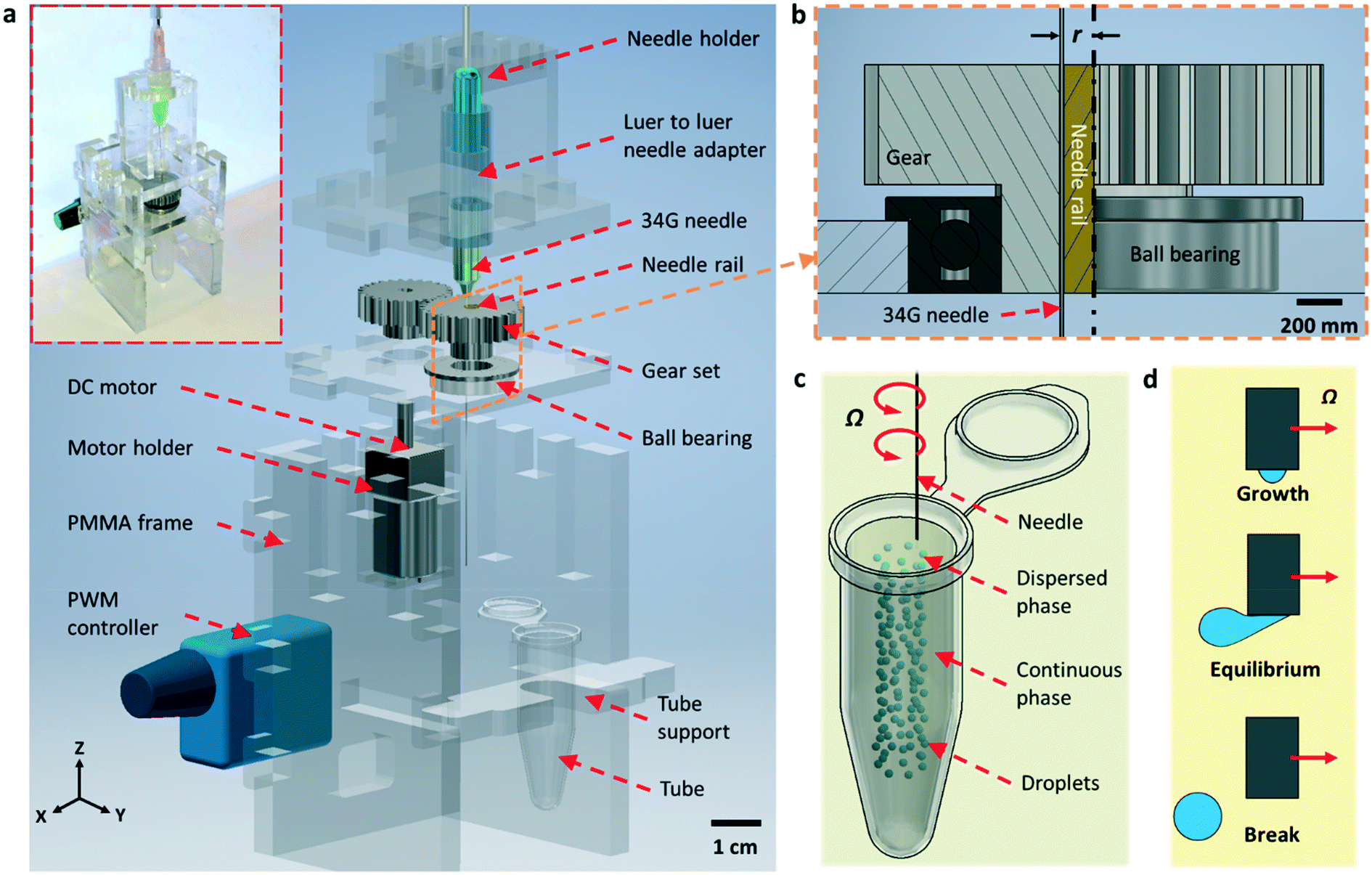 | ||
| Fig. 1 Schematic illustration of the revolving needle emulsion generator (RNEG). a) Exploded schematic representation of the RNEG. The upper inset shows an actual image of the assembled system. b) Zoomed-in schematic representation of the off-axis eccentric setup. c) Illustration of the generated microdroplets in a test tube. d) Schematics of the droplet formation process. | ||
After construction, the needle tip was immersed in the oil phase contained in a micro-centrifuge tube. The aqueous solution was pumped into the needle at a constant flow rate while revolving, and the aqueous phase was broken into uniform droplets in the oil phase (Fig. 1c). During the breaking process, the droplet grows in a spherical shape at the initial stage and then distorts under the shear force coming from the viscous flow of oil. A neck is formed at the tip of the needle and then the droplet breaks when the drag force exerted on the emerging droplet cannot balance the interfacial tension that resists the deformation of the droplet (Fig. 1d).
We firstly conducted numerical simulations to examine the feasibility of operation. For the droplet breakup process, the revolving needle tip submerged in the oil phase can be regarded as a fixed needle immersed in a perpendicular flow field whose linear velocity is equal to the revolving speed of the needle tip. Fig. 2a shows the simulated sequential droplet breaking process when we set the inlet flow rate at 5 μL min−1 and the equivalent revolving speed at 2000 rpm. The parameters used for the simulation are given in Table S1.† Our result shows that the shear induced by the continuous phase during revolution breaks the dispersed phase in a way which is similar to the case of droplet generation using a T-junction microfluidic channel. The simulation also indicates that the droplet size is inversely proportional to the revolving speed and proportional to the flow rate (see Fig. S1 and S2†). We examined the breakup process by dispersing deionised (DI) water mixed with blue food dye in mineral oil (viscosity of 30 mPa s, containing 3 wt% Span-80 surfactants). Fig. 2b shows sequential snapshots taken from a high-speed camera during the production of a water-in-oil microdroplet (Ω = 1000 rpm and Q = 5 μL min−1, see also Movie S1†). The experimental results show good agreement with the ones obtained from numerical simulation. Under our experimental conditions, only interfacial tension and drag force play major roles in the net force. We expect that the balance between these two major forces leads to a simple inverse proportionality between the droplet diameter and the revolving velocity of the needle tip.
 | ||
| Fig. 2 Droplet formation process. a) Numerical simulation results of the droplet breakup process at the needle tip. b) Sequential snapshots showing the formation of aqueous microdroplets using the RNEG (red dashed area is the needle tip and it moves from left to right). | ||
In our platform, breakup of the emerging droplet occurs when the disruptive drag force induced by the revolving motion overcomes the interfacial tension that resists deformation of the droplet. Neglecting the effects of the dispersed phase inertia, by balancing the drag (Fdrag) and surface tension induced force (Fγ), we can obtain the following equation to estimate the diameter of the produced microdroplets Ddroplet (ref. 9) (see Fig. S4† for the detailed deduction of this equation):
 | (1) |
 | (2) |
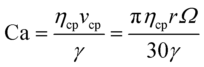
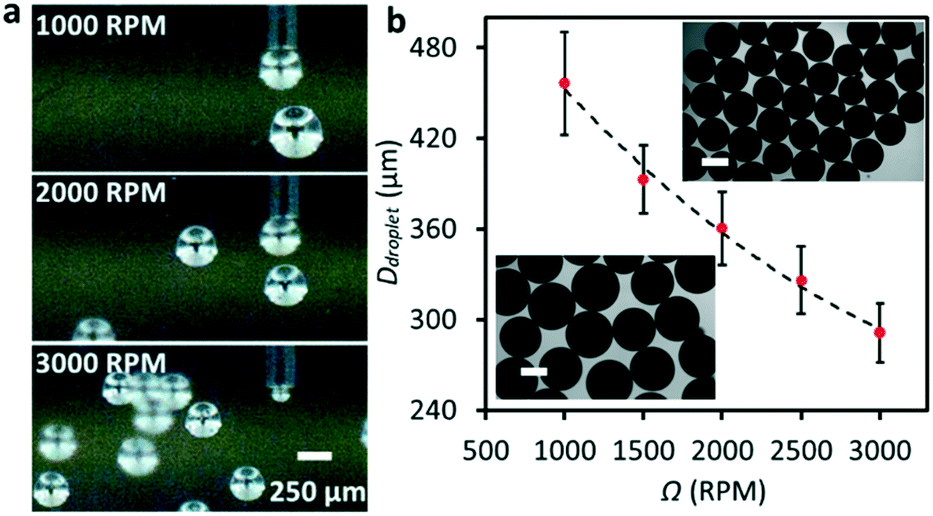
After understanding the working mechanism, we next characterised the performance of the platform for water microdroplet production. Keeping the flow rate Q constant at 5 μL min−1, we observed that increasing Ω efficiently reduced the size of the produced microdroplets, as shown in Fig. 3a (see also Movie S2†). The decrease in the droplet size is due to the increase of Ca (from ∼0.29 at 500 rpm to ∼1.77 at 3000 rpm). Without revolution, droplets were formed due to gravity and surface tension acting on them. The diameter of the produced water droplets reduced significantly to ∼250 μm upon the application of a 500 rpm revolving speed, and the droplet size can be further decreased to ∼70 μm when increasing the speed to 3000 rpm. Fig. 3b shows that at a constant Ω (3000 rpm in this case), a higher Q resulted in the production of droplets with a larger size (see also Movie S3†). Fig. 3c and d summarise the diameters of the produced microdroplets with respect to Ω and Q, respectively. The diameter of the produced microdroplet ranges from ∼70 to ∼250 μm at different revolving speeds, and the coefficient of variation (CV) of the size is less than 7%.
 | ||
| Fig. 3 Controlling the size of the produced water microdroplets. Snapshots taken from a high-speed camera showing the production of water microdroplets at a) different revolving speeds Ω, and b) different flow rates Q. Plots of the droplet diameter Ddropletvs. applied c) Ω and d) Q corresponding to the micrographs in a) and b), respectively. The inset images show microdroplets produced at Ω = 2000 rpm and Q = 20 μL min−1, respectively. Scale bars are 250 μm. e) 3D velocity profile obtained from numerical simulation in a microcentrifuge tube introduced by the revolving needle. (f) Velocity profile and droplet falling trace on the y–z plane at revolving speeds of 1000 and 2000 rpm. | ||
With a modest flow rate and revolving speed, the RNEG can produce monodispersed microdroplets, which sink to the bottom of the tube due to the higher density of the aqueous phase compared to oil. However, we found that the increase in revolving speed of the needle also induced strong vortices which prevented the emulsions from sinking. In order to overcome this problem, we further numerically investigated the flow field caused by the revolving needle. Fig. 3e shows the 3D velocity distribution of liquid around the needle at 1000 rpm, in which we can see that the high-speed motion of the needle in the x–y plane induces vortices in the y–z plane. Fig. 3f shows the 2D velocity profile on the y–z plane and the droplet trace influenced by different revolving speeds. Our simulation shows the induction of a flow travelling upward along the revolving axis and the formation of clockwise-circulated vortices on the y–z plane. When the revolving speed is moderate, the flow field has a minor effect on the droplet trace and the droplet sinks due to the difference in the density between the dispersed and continuous phases. However, at a higher revolving speed, the sinking speed of the droplets will slow down due to the influence of vortices. By assembling an additional soft tubing onto the needle tip to achieve co-axis emulsification, we further demonstrated the ability of the RNEG to generate double emulsions, as shown in Fig. S5.†
In addition to water droplets, we further investigated the capability of RNEG for producing microdroplets of liquids that are conventionally difficult to produce in microfluidic platforms.9,23 This includes liquids with high surface tension, such as EGaIn liquid metal (75 wt% gallium and 25 wt% indium). In comparison with water, EGaIn has a remarkably ∼7.7 times higher surface tension (∼624 mN m−1). In flow-focusing microfluidic devices, the continuous phase must be a liquid with high viscosity in order to generate sufficient shear for pinching off liquid metal into discrete droplets. This induces a very high pressure drop within the microfluidic channels, which may damage the microfluidic system. Our off-chip system is naturally suitable for generating liquid emulsions with high surface tension and the numerical simulation results also demonstrated its ability (see Fig. S3†). The RNEG avoids the use of microfluidic channels, and instead, we filled the microcentrifuge tube with a corn syrup–water mixture (ratio of 2:1, w/w; viscosity of ∼110 mPa s) and pumped EGaIn liquid metal to the needle. We successfully produced EGaIn microdroplets with a relatively uniform size by revolving the needle submerged in the corn syrup–water mixture (see Movie S4†). The massive EGaIn production can be controlled by varying the revolving speed (see Fig. 4a) and flow rate (see Fig. S6†). Fig. 4b plots the diameters of the obtained microdroplets with respect to Ω at a constant flow rate Q = 20 μL min−1. Similar to the case of water, increasing Ω reduces the size of the droplets. A native oxide layer can form on the surface of EGaIn when exposed to oxygen, and this layer can prevent the produced microdroplets from merging, allowing for mass production of the liquid metal microdroplets. The insets of Fig. 4b show the optical microscopy images of the collected EGaIn droplets. Due to the high density and surface tension, the smallest diameter of the liquid metal droplets was ∼270 μm (Ω = 3000 rpm and Q = 10 μl min−1), which is larger than the produced water droplets.
 | ||
| Fig. 4 Production of EGaIn microdroplets using the RNEG. a) Images taken from a high-speed camera showing the production of liquid metal microdroplets at different revolving speeds. b) Plot of the droplet diameter Ddropletvs. Ω. The inset images show the EGaIn droplets produced when Ω is 1500 and 3000 rpm, respectively, and Q is 20 μL min−1. | ||
Droplet microfluidic platforms have been widely adopted for microgel production.24–26 In general, the production process involves three main steps: (1) producing monodisperse microdroplet emulsions in a microfluidic device, (2) shaping the microdroplets in microchannels, and (3) solidifying the droplets to form microparticles by physical, chemical, or photochemical methods. Following a similar process, we further demonstrated the ability of this generator to produce spherical hydrogel microparticles in a low-viscosity mineral oil and we attempted to adapt our platform toward biological applications. Fig. 5a and b show the scheme of the experimental setup and workflow, in which we proposed to use a beam of UV light (wavelength of 365 ± 5 nm, power density of ∼2000 mW cm−2) to solidify the microdroplets immediately after emulsification. In addition, by centrifugation, we achieved phase transfer of microdroplets from an oil phase to a water phase without a complicated washing process. We prepared the PEGDA solution by mixing 1 mL of PEGDA with 9 mL of DI water (mixed with blue food dye) and then adding 100 μL of 2-hydroxy-2-methylpropiophenone into the solution. The prepared PEGDA solution was fully mixed using a vortex generator for 5 min before being pumped into the platform. Unlike the case of water droplet generation where the centrifuge tube is only filled with mineral oil, we also added DI water at the bottom to demonstrate phase transfer after particle production. The flow rate of the PEGDA solution was set at 5 μL min−1. After droplet generation and gelation, the produced microgels congregated at the water–oil interface (Fig. 5b). Then, the tube was centrifuged at 3000 rpm (604g) for 30 s to transfer microgels in the aqueous phase. After transfer, the food dye dissolved in the microgels diffused into the water phase, as indicated by the colour change shown in Fig. 5b. We observed the successful mass production and transfer of PEG microgels using the platform, and Fig. 5c shows that the diameter of the produced particles is reduced to ∼80 μm when Ω is increased to 3000 rpm. Fig. 5d shows the collected transparent PEG microgels in DI water. Due to the low interfacial tension of the mixed PEGDA solution, droplet production in jetting mode was clearly observed at a high flow rate (see Fig. S7†).
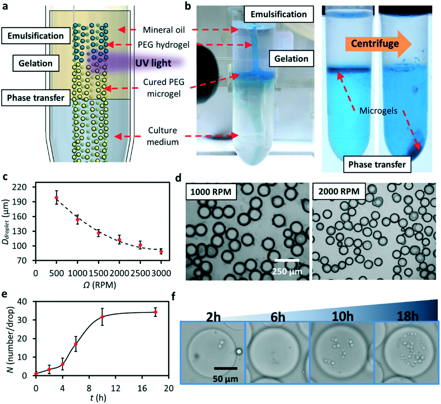 | ||
| Fig. 5 Production of microgels and growth of single yeast cells. a) Schematic illustration of the workflow for microgel production. b) Actual images of the PEG microgel production process, including emulsification, gelation and phase transfer. c) Plot of Ddropletvs. Ω at a constant flow rate of 5 μL min−1. d) Microscopy images of the produced PEGDA microgels at Ω = 1000 and 2000 rpm. e) Plot of the number of cells per microgel droplet vs. cultivation time. (f) Bright-field microscopy images of yeast cell growth in PEGDA microgels at four selected time points. | ||
Cell culture in microdroplets surrounded by an oil phase is undesirable due to the lack of oxygen and nutrients and accumulation of metabolites.27 The phase transfer of the RNEG produced hydrogel particles allows media exchange with the surrounding environment, thereby enabling long-term culture of encapsulated cells. To examine this, we adapted the workflow given in Fig. 5a and b for quantitatively tracking the growth of single yeast cells. Yeast has been widely used as a “cell factory” in industrial fermentation processes to produce a wide range of valuable products that are used extensively in the manufacturing, pharmaceutical, cosmetic, food, textile and chemical industries.28–32 Similar to the standard method used to measure the growth rate of bulk populations, the procedure of using microfluidic droplets in this study to quantify the growth of single yeast cells includes three main steps: (1) generating uniformly distributed cell-laden microgels, (2) tracking the number of cells per droplet as cells grow over time, and (3) analysing the growth rate of each cell within the microgel.
We replaced DI water with yeast cell suspension to prepare PEGDA solution and utilised a fresh culture medium (YPD) as the aqueous phase in the centrifuge tube. Before cell encapsulation within microdroplets, cell density was diluted to an OD600 of 0.1 (3 × 10⁶ cells per mL) to ensure that most cell-laden droplets contain single or no cell.33,34 Since UV irradiation can cause cell damage or death, we conducted photoinitiated polymerisation by reducing the UV light density. After phase transfer within the centrifuge tube, the cells were further kept at 30 °C for 18 hours and meanwhile we tracked the growth of the cells within microgels. The bright-field images given in Fig. 5f show that single yeast cells can grow and divide over time within microgels. We plotted the number of cells per droplet N at six selected time points, as shown in Fig. 5e. In general, the number of cells per droplet increased over time: single yeast cells (at 0 h) grew to 3.4 ± 1.2 at 2 h, and eventually reached 34.3 ± 4.3 at 18 h. We calculated the growth rate μ (μ = dln(N)/dt) based on N over time of culture t. We found that over 18 hours of culture, the value of μ of single yeast cells in microgels is calculated to be 0.19 ± 0.01 h−1, which is similar to that of bulk populations (0.21 ± 0.01 h−1).
Conclusion
In summary, we developed an integrated and modular revolving needle emulsion generator (RNEG) for the versatile and high-throughput production of emulsions in an off-chip manner. The size of the produced droplets can be precisely controlled by varying the flow rate of the dispersed phase and the revolving speed of the needle. We showed that the RNEG can produce microdroplets with diameters ranging from tens to hundreds of micrometres. Unlike conventional microfluidics-based approaches, the operation of the RNEG is simple and straightforward, which significantly minimises the equipment and simplifies the process required for droplet generation. We further examined the principle of operation using numerical simulations and established a simple model to predict the size of the produced droplets. In addition to water, we demonstrated the capability of the platform for producing microdroplets of liquid with a large surface tension (EGaIn liquid metal). Moreover, the RNEG can produce PEG hydrogel microparticles and transfer them into the water phase simply by integrating UV light and centrifugation. Using this ability, we demonstrated the encapsulation and cultivation of single yeast cells within PEG microgels. We compared the performance of the RNEG with some other emerging off-chip emulsion generation techniques, as summarised in Table S2.† The RNEG has several advantages, including cost-effective manufacturing, user-friendly operation, easy maintenance, high controllability, and versatile working environment (can produce microdroplets in different types of containers). Therefore, we believe that the remarkable abilities demonstrated by the RNEG will unleash the vast potential provided by microdroplets for revolutionising future biological and chemical analyses.Contributions
S.-Y. T., Y. Z., and W. L. proposed the project and conceived the idea. Y. Z. and S.-Y. T. designed the experiments. Y. Z., Q. Z., H. L., and D. Y. performed the experiments. Y. Z., S.-Y. T., H. L., M. L., D. Y., and J. G. analysed the results. S.-Y. T. and W. L. supervised the project. All authors participated in writing the manuscript.Conflicts of interest
The authors declare no competing financial interest.Acknowledgements
This work is supported by the Australian Research Council (ARC) Discovery Project (Grant no. DP200102269).References
- Y. Ding, P. D. Howes and A. J. de Mello, Anal. Chem., 2020, 92, 132–149 CrossRef CAS.
- L. Shang, Y. Cheng and Y. Zhao, Chem. Rev., 2017, 117, 7964–8040 CrossRef CAS.
- S. Mashaghi, A. Abbaspourrad, D. A. Weitz and A. M. van Oijen, TrAC, Trends Anal. Chem., 2016, 82, 118–125 CrossRef CAS.
- P. Zhu and L. Wang, Lab Chip, 2017, 17, 34–75 RSC.
- R. H. Cole, S.-Y. Tang, C. A. Siltanen, P. Shahi, J. Q. Zhang, S. Poust, Z. J. Gartner and A. R. Abate, Proc. Natl. Acad. Sci. U. S. A., 2017, 114, 8728–8733 CrossRef CAS.
- Z. Chen, P. Liao, F. Zhang, M. Jiang, Y. Zhu and Y. Huang, Lab Chip, 2017, 17, 235–240 RSC.
- Y. Fu, F. Zhang, X. Zhang, J. Yin, M. Du, M. Jiang, L. Liu, J. Li, Y. Huang and J. Wang, Commun. Biol., 2019, 2, 147 CrossRef.
- Z. Chen, Y. Fu, F. Zhang, L. Liu, N. Zhang, D. Zhou, J. Yang, Y. Pang and Y. Huang, Lab Chip, 2016, 16, 4512–4516 RSC.
- S.-Y. Tang, K. Wang, K. Fan, Z. Feng, Y. Zhang, Q. Zhao, G. Yun, D. Yuan, L. Jiang, M. Li and W. Li, Anal. Chem., 2019, 91, 3725–3732 CrossRef CAS.
- Z. Lian, Y. Ren, J. He, G. Z. Chen and K. S. Koh, Microfluid. Nanofluid., 2018, 22, 145 CrossRef.
- T. Li, L. Zhao, W. Liu, J. Xu and J. Wang, Lab Chip, 2016, 16, 4718–4724 RSC.
- Z. Lian, Y. Chan, Y. Luo, X. Yang, K. S. Koh, J. Wang, G. Z. Chen, Y. Ren and J. He, Electrophoresis, 2020, 41, 891–901 CrossRef CAS.
- M. M. Dragosavac, G. T. Vladisavljević, R. G. Holdich and M. T. Stillwell, Langmuir, 2012, 28, 134–143 CrossRef CAS.
- G. T. Vladisavljević, I. Kobayashi and M. Nakajima, Microfluid. Nanofluid., 2012, 13, 151–178 CrossRef.
- P. Xu, X. Zheng, Y. Tao and W. Du, Anal. Chem., 2016, 88, 3171–3177 CrossRef CAS.
- E. K. Sackmann, L. Majlof, A. Hahn-Windgassen, B. Eaton, T. Bandzava, J. Daulton, A. Vandenbroucke, M. Mock, R. G. Stearns, S. Hinkson and S. S. Datwani, J. Lab. Autom., 2016, 21, 166–177 CrossRef.
- Y. Wang, S. Shaabani, M. Ahmadianmoghaddam, L. Gao, R. Xu, K. Kurpiewska, J. Kalinowska-Tluscik, J. Olechno, R. Ellson, M. Kossenjans, V. Helan, M. Groves and A. Dömling, ACS Cent. Sci., 2019, 5, 451–457 CrossRef CAS.
- B. Colin, B. Deprez and C. Couturier, SLAS Discovery, 2019, 24, 492–500 CAS.
- A. Z. Nelson, B. Kundukad, W. K. Wong, S. A. Khan and P. S. Doyle, Proc. Natl. Acad. Sci. U. S. A., 2020, 117, 5671–5679 CrossRef CAS.
- M. N. Hatori, S. C. Kim and A. R. Abate, Anal. Chem., 2018, 90, 9813–9820 CrossRef CAS.
- D. Foresti, K. T. Kroll, R. Amissah, F. Sillani, K. A. Homan, D. Poulikakos and J. A. Lewis, Sci. Adv., 2018, 4, eaat1659 CrossRef CAS.
- P. E. Frommhold, A. Lippert, F. L. Holsteyns and R. Mettin, Exp. Fluids, 2014, 55, 1716 CrossRef.
- Y. Zhang, S.-Y. Tang, Q. Zhao, G. Yun, D. Yuan and W. Li, Appl. Phys. Lett., 2019, 114, 154101 CrossRef.
- M. Li, M. van Zee, C. T. Riche, B. Tofig, S. D. Gallaher, S. S. Merchant, R. Damoiseaux, K. Goda and D. Di Carlo, Small, 2018, 14, 1803315 CrossRef.
- K. G. Lee, T. J. Park, S. Y. Soo, K. W. Wang, B. I. I. Kim, J. H. Park, C.-S. Lee, D. H. Kim and S. J. Lee, Biotechnol. Bioeng., 2010, 107, 747–751 CrossRef CAS.
- L. Liu, C. K. Dalal, B. M. Heineike and A. R. Abate, Lab Chip, 2019, 19, 1838–1849 RSC.
- E. K. Bowman and H. S. Alper, Trends Biotechnol., 2020, 38, 701–714 CrossRef CAS.
- C. R. Álvarez-Chávez, S. Edwards, R. Moure-Eraso and K. Geiser, J. Cleaner Prod., 2012, 23, 47–56 CrossRef.
- R. A. Gonzalez-Garcia, T. McCubbin, L. Navone, C. Stowers, L. K. Nielsen and E. Marcellin, Fermentation, 2017, 3, 21 CrossRef.
- K.-K. Hong and J. Nielsen, Cell. Mol. Life Sci., 2012, 69, 2671–2690 CrossRef CAS.
- B. W. de Jong, S. Shi, V. Siewers and J. Nielsen, Microb. Cell Fact., 2014, 13, 39 CrossRef.
- Y. Chen, L. Daviet, M. Schalk, V. Siewers and J. Nielsen, Metab. Eng., 2013, 15, 48–54 CrossRef CAS.
- D. J. Collins, A. Neild, A. de Mello, A.-Q. Liu and Y. Ai, Lab Chip, 2015, 15, 3439–3459 RSC.
- H. Liu, M. Li, Y. Wang, J. Piper and L. Jiang, Micromachines, 2020, 11, 94 CrossRef.
Footnote |
| † Electronic supplementary information (ESI) available. See DOI: 10.1039/d0lc00939c |
| This journal is © The Royal Society of Chemistry 2020 |