
 Open Access Article
 This Open Access Article is licensed under a
 Creative Commons Attribution 3.0 Unported Licence
On-chip density-based sorting of supercooled droplets and frozen droplets in continuous flow†‡
Grace C. E.
Porter
 *ab,
Sebastien N. F.
Sikora
a,
Jung-uk
Shim
b,
Benjamin J.
Murray
a and
Mark D.
Tarn
ab
*ab,
Sebastien N. F.
Sikora
a,
Jung-uk
Shim
b,
Benjamin J.
Murray
a and
Mark D.
Tarn
ab
aSchool of Earth and Environment, University of Leeds, Leeds, LS2 9JT, UK. E-mail: ed11gcep@gmail.com; Tel: +44 (0)113 343 5605
bSchool of Physics and Astronomy, University of Leeds, Leeds, LS2 9JT, UK
First published on 21st September 2020
Abstract
The freezing of supercooled water to ice and the materials which catalyse this process are of fundamental interest to a wide range of fields. At present, our ability to control, predict or monitor ice formation processes is poor. The isolation and characterisation of frozen droplets from supercooled liquid droplets would provide a means of improving our understanding and control of these processes. Here, we have developed a microfluidic platform for the continuous flow separation of frozen from unfrozen picolitre droplets based on differences in their density, thus allowing the sorting of ice crystals and supercooled water droplets into different outlet channels with 94 ± 2% efficiency. This will, in future, facilitate downstream or off-chip processing of the frozen and unfrozen populations, which could include the analysis and characterisation of ice-active materials or the selection of droplets with a particular ice-nucleating activity.
Introduction
The heterogeneous nucleation of ice is of fundamental importance to fields as diverse as cryobiology,1 atmospheric science,2,3 the pharmaceutical industry,4 and food science.5 However, our quantitative and mechanistic understanding and control over ice nucleation is poor. Many materials are completely inert when it comes to ice nucleation, and in the absence of the rare sites that catalyse ice nucleation, droplets of water can supercool. They remain in a supercooled liquid state down to ∼−35 °C (depending on droplet volume), whereupon they can freeze homogeneously.6,7 This means that, in a population of droplets containing ice-nucleating material, some droplets will contain ice-active particles and freeze at warmer temperatures, while others might not and so remain in a supercooled liquid state. This heterogeneity in ice nucleation makes freezing processes challenging to predict and control and has implications for a number of fields.In cryopreservation, for instance, the survival of biological matter is strongly influenced by the freezing process. Some cryopreservation strategies avoid ice formation by cooling and vitrifying the samples, whereas others involve minimising the extent of supercooling by nucleating ice at as high a temperature as possible by inducing ice nucleation under controlled conditions.1,8,9 If some aliquots freeze or vitrify in an optimal manner while others do not, this could result in a mixture of samples containing cells or tissues of varying viability. In principle, if the samples that have undergone controlled ice nucleation could be selected and only those aliquots expected to contain viable biological matter stored, the quality and reproducibility of the cryopreserved samples would be improved.
The formation of ice is also important for the Earth's atmosphere and climate. The properties and lifetime of clouds is strongly influenced by the formation of ice, which can form homogeneously or can be triggered heterogeneously by ice-nucleating particles (INPs).10,11 In atmospheric ice nucleation research, an aerosol sample from the lab or field may be analysed to determine the temperature at which nucleation occurs and the concentration of ice-nucleating particles in the sample.2,3 However, the identification of these rare particles in a bulk sample of aerosol particles can be difficult. The separation of ice-nucleating materials from atmospheric samples would greatly facilitate their identification and characterisation, allowing a greater understanding of their sources and global transport.
In these areas and more, an ability to separate frozen from supercooled droplets would be advantageous. A desirable mechanism for achieving such a separation would be to first trigger the nucleation of ice in supercooled water droplets at a defined sub-zero temperature. Only those droplets containing material with the ability to nucleate ice at that temperature would induce ice nucleation, leaving the remaining droplets unfrozen. Since ice and water have different densities (ρwater > ρice), they are susceptible to separation based on their relative buoyancy in an immiscible medium (Fig. 1a), and this principle may be used to separate frozen ice crystals from unfrozen water droplets.
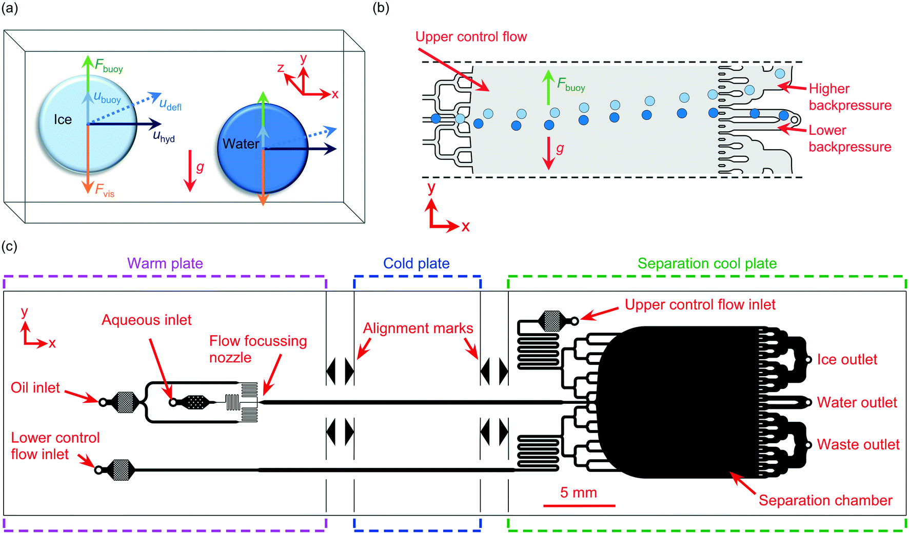 | ||
| Fig. 1 Principle of the on-chip sorting of ice crystals and water droplets in continuous flow, based on their differences in buoyancy. (a) A schematic showing the buoyancy forces (Fbuoy) that give rise to different velocities in the y-direction (ubuoy), opposite to the direction of gravity (g), for the water droplets and ice crystals due to their different densities in an oil medium. When the droplets and crystals reach their terminal velocity, Fbuoy is balanced by the opposing viscous forces (Fvis). The droplets and crystals are driven in the x-direction with a hydrodynamic velocity (uhyd) and experience a deflection velocity (udefl) to differing extents depending on their respective ubuoy values. (b) Water droplets and ice crystals experiencing different Fbuoy forces in a tall microfluidic chamber are sorted into different outlet channels. (c) The design of the microfluidic chip. Water-in-oil droplets were generated in a flow focussing nozzle on a warm plate, before passing over a cold plate at a set temperature that froze part of a population of droplets. The frozen and unfrozen droplets then entered a vertically oriented separation chamber for their density-based sorting. | ||
Fahy et al.12 found that ice crystals that formed in a solution of 50% w/w propylene glycol in water floated to the top of their container upon cooling to sub-zero temperatures, and later suggested that this effect could be leveraged to separate frozen from unfrozen droplets via centrifugation or drop-sorting techniques.13 Recently, Kamijo and Derda14 developed a “freeze-float” droplet selection system for the sorting of ice-nucleating material populations. 1 μL droplets were suspended in low viscosity silicone oil on a cushion layer of fluorinated oil (ρfluorinated oil > ρwater > ρsilicone oil > ρice) within a cuvette, and then cooled to sub-zero temperatures. As droplets froze, they floated to the top of the silicone oil layer, allowing their collection for analysis of their contents. However, the selection procedure was somewhat slow and only tens of droplets could be processed per experiment.
Microfluidic technology offers a number of elegant options for performing particle and droplet separations in continuous flow,15–18 which can enable the high-throughput sorting of different species with high efficiency and in large numbers. In a typical continuous flow sorting platform, a mixed particle population will enter a channel or chamber and experience a lateral force, causing the populations to migrate laterally across the channel/chamber to differing extents for collection from different outlet channels.
Several examples exist of on-chip continuous density-based sorting of particles and cells in the vertical direction due to gravity,19,20 including the use of split flow thin-cell fractionation (SPLITT),21 3D-printed devices,22 diamagnetic levitation,23 and in numerical simulations.24 Density-based separations have also been performed in a horizontal orientation via the use of acoustic forces,25–28 centrifugal platforms,29–31 sedimentation pinched-flow fractionation in a centrifugal device,32 and could potentially also be achieved in inertial microfluidic devices.33 However, none of these examples, nor any other continuous separation methods to our knowledge, have been applied to the sorting of ice crystals from supercooled water droplets.
Here, we demonstrate a microfluidic device for the density-based sorting of ice crystals from unfrozen water droplets in continuous flow (Fig. 1b). The proof-of-concept device utilises our recently developed microfluidic apparatus for the generation and freezing of water-in-oil droplets for ice-nucleating particle analysis, the Lab-on-a-Chip Nucleation by Immersed Particle Instrument (LOC-NIPI).34 In the new device described here, the generated ice crystals and supercooled water droplets enter a downstream separation chamber with multiple outlet channels to allow sorting in a “free-flow” format, similar to designs used in free-flow magnetophoresis,35 electrophoresis,36,37 isotachophoresis,38 acoustophoresis,26 and diamagnetophoresis.39,40 Since the sorting mechanism leverages the intrinsic differences in density between the ice and water, the separation acts in a passive manner without the need for actively applied external forces and associated apparatus.
The new platform was tested by generating droplets containing Snomax® Snow Inducer, comprised of highly ice-active material from the Pseudomonas syringae plant pathogen,41,42 at a concentration that resulted in around half of the droplet population freezing. The subsequent behaviour of the ice crystals and supercooled water droplets was then observed as they flowed through the separation chamber. This concept is particularly timely given the recent surge in microfluidic platforms being developed for the droplet-based study of ice nucleation,43–48 including for applications such as cryobiology49–53 and atmospheric science.34,54–62
Theory
The migration of an object, such as a droplet, due to its buoyancy in an immiscible medium depends on the buoyancy force, Fbuoy, exerted upon it:| Fbuoy = (ρp − ρm) Vpg = Δρ Vpg | (1) |
As a droplet moves through a medium, it also experiences a viscous drag force, Fvis, that opposes its movement. In flow conditions with low Reynolds numbers (Re ≪ 1) and low particle Reynolds numbers (Rep < 0.2), this frictional force can be calculated using Stokes' law:
| Fvis = 6 πηr ubuoyCW | (2) |
When the droplet reaches its terminal velocity as it moves through a medium, the viscous forces are equal but opposite to the buoyancy forces, i.e. Fvis = Fbuoy. Using this assumption, eqn (1) and (2) can be rearranged to allow the sedimentation/creaming velocity, ubuoy, of the droplet to be determined:19
 | (3) |
The droplet will also have a velocity in the x-direction due to the applied hydrodynamic flow, uhyd (m s−1). Therefore, the droplet has velocities in both the y-direction (ubuoy) and the x-direction (uhyd), and the resultant deflection velocity (udefl) is the sum of the two vectors:
| udefl = ubuoy + uhyd | (4) |
Theoretical values for Fbuoy and ubuoy were calculated for supercooled water droplets and ice crystals using eqn (1)–(3) for a temperature range of 0 to −35 °C, in a fluorinated oil medium of Novec™ 7500 Engineered Fluid. Viscosity (η) and density (ρm) values for Novec™ 7500 were obtained using equations from the manufacturer's product information, as shown in the ESI† (eqn (S5)–(S8)). The density (ρp) of supercooled water and ice were calculated from eqn (S10) (from Hare and Sorensen67) and eqn (S11) (from Pruppacher and Klett6) in the ESI,† respectively. The viscous drag coefficient (Cw) was calculated as described in eqn (S4) in the ESI† for a microchannel with a z-direction width of 140 μm.
The change in theoretical Fbuoy with temperature for a water droplet (115 μm nominal diameter, 796 pL) and an ice crystal (117.2–118.4 μm diameter depending on temperature, 842–869 pL) is shown in Fig. S3a in the ESI,† and demonstrates the greater buoyancy forces on the ice crystals across the full temperature range of 0 to −35 °C, below which homogeneous freezing is expected to start occurring for water droplets of this size. The difference in Fbuoy between the ice crystals and water droplets, ΔFbuoy, is shown theoretically in Fig. S3b in the ESI,† and provides the means by which the two can be separated in continuous flow. This effect is further reflected in the theoretical ubuoy values, as shown in Fig. S4a in the ESI,† which indicates the increased velocity of ice crystals in the y-direction of the separation chamber compared to the water droplets. The difference in ubuoy between the water droplets and ice crystals, Δubuoy, determines the extent of the separation of the two components in flow, and this difference is shown theoretically in Fig. S4b in the ESI.† The Fbuoy and ubuoy values for water and ice are negative in Novec™ 7500 Engineered Fluid, indicating that they would each cream rather than sediment with respect to gravity, but are shown in ESI† Fig. S3 and S4 as positive values for simplicity.
It must also be noted that whilst the cold stages could each reach temperatures below −40 °C, the temperature of the separation chamber was controlled separately to the main channel where freezing occurred. The separation chamber was held at a temperature slightly below 0 °C, which would prevent any ice crystals formed in the main channel from melting, but would also not trigger ice nucleation in the unfrozen supercooled water droplets. This meant that separations would occur in the temperature regime at which the differences in Fbuoy and ubuoy were maximised (e.g. between 0 to −5 °C).
Experimental
Chemicals
3M™ Novec™ 7500 Engineered Fluid, a fluorinated heat transfer oil, was purchased from Fluorochem Ltd. (Hadfield, UK). Pico-Surf™ 1 fluorinated surfactant (5% w/w in Novec™ 7500) was purchased from Sphere Fluidics Ltd. (Cambridge, UK), and further diluted to 0.2% w/w in Novec™ 7500. Snomax® Snow Inducer (Snomax International, Englewood, CO, USA) was purchased from SMI Snow Makers AG (Thun, Switzerland) and prepared in purified water to a concentration of 0.01% w/w. The purified water (18.2 MΩ cm at 25 °C, 0.22 μm filtered) was obtained via a Sartorius arium® pro water purification system. Poly(dimethylsiloxane) (PDMS, Dow Corning® Sylgard® 184 kit) was purchased from Ellsworth Adhesives (East Kilbride, UK). MicroChem SU-8 2075 photoresist was purchased from A-Gas Electronic Materials Ltd. (Rugby, UK).Microfluidic chip design
The microfluidic chip design was adapted from the continuous droplet freezing design of Tarn et al.,34 with the downstream addition of a wide separation chamber and corresponding inlet and outlet channels (Fig. 1c). Briefly, the design featured a flow focussing nozzle (40 μm wide) for droplet generation, with pillar-based particle filters and fluidic resistors located between the inlets and the nozzle. The nozzle expanded into a long, central main channel (300 μm wide) for the freezing of droplets as they flowed down the channel. The main channel then fed into a 10.9 mm wide by 11.6 mm long separation chamber, which was also fed by an “upper control flow” inlet channel (200 μm wide) at the top of the chamber and a “lower control flow” inlet channel (200 μm wide) at the bottom via branching inlet channels.Branched outlet channels (218 μm wide each) were situated at the end of the separation chamber and consisted of an ice crystal outlet system from the upper part of the chamber, a water droplet outlet from the middle of the chamber, and a waste outlet system from the lower part of the chamber. The water droplet outlet was designed to have lower backpressure than the ice crystal outlet in order to capture any water droplets that were tending slightly towards the ice crystal outlet. Alignment marks were added to the design to enable alignment of the chip over a series of temperature-controlled plates on a cold stage platform.
Fabrication of the microfluidic device
The microfluidic device was fabricated in PDMS, as described by Tarn et al.,34 using standard soft lithography techniques.68–70 A detailed description of the process is provided in section 8 of the ESI.† Briefly, the microfluidic chip design was patterned via a mask aligner onto SU-8 2075 photoresist that had been spin-coated onto a silicon wafer. Following photodevelopment, PDMS was poured onto the mould, degassed, and cured. The PDMS was then peeled off the mould, access holes (1 mm Ø) were punched into it, and it was finally bonded to a glass microscope slide via plasma treatment to yield the final device with a channel depth of 140 μm (Fig. 2a). | ||
| Fig. 2 Setup of the microfluidic sorting apparatus. (a) The microfluidic chip fabricated in poly(dimethylsiloxane) (PDMS) and with tubing connected. (b) Photograph of the microfluidic device situated in the cold stage platform. Alignment marks on the chip allowed its accurate placement over three temperature-controlled plates that aligned with the droplet generation nozzle, the main channel for droplet freezing, and the separation chamber. The cold stage platform was placed on its side so that the separation chamber was oriented vertically. | ||
Experimental setup
A detailed description of the experimental setup (Fig. 2b) is provided in section 8 of the ESI,† and largely employed the apparatus and setup of the LOC-NIPI described by Tarn et al.34 Polyethylene tubing (0.38 mm i.d. × 1.09 mm o.d.) was inserted into the access holes of the PDMS chip and the inlet tubing was connected to syringes located in syringe pumps (PHD Ultra, Harvard Apparatus, Biochrom Ltd., UK). The chip was placed into the chamber of a custom-built cold stage that had been turned on its side, such that the separation chamber of the chip was oriented vertically so that its width (10.9 mm) was now its height and its height (140 μm) was now its width, and clips were used to hold the chip in place. A similar sideways orientation had been employed by Stan et al.71,72 in their studies of the buoyancy and lift forces on water droplets and ice crystals.The cold stage platform comprised three temperature-controlled aluminium plates that were set into a 3D printed body. The plate temperatures were controlled using Peltier elements via a proportional-integral-derivative (PID) loop, and the Peltier elements were themselves cooled using liquid heat exchangers connected to a refrigerated recirculating chiller. The alignment marks of the microfluidic chip were used to ensure that each major section of the chip (i.e. the flow focussing junction, main channel where freezing occurred, and separation chamber) was situated across one of the three plates (see Fig. 1c). The previous version of the platform required the microfluidic chips to be coated with a layer of chromium on the underside in order to provide a reflective surface on which to visualise droplets using reflected light microscopy.34 Here, however, the aluminium plates of the cold stage were polished to render them much more reflective, meaning that droplets could be observed in the chip without the need for a chromium layer.
A Perspex lid was placed onto the cold stage platform to form a chamber, and dry air was pumped into the chamber to purge it of moisture. Visualisation of the microchannels and separation chamber inside the microfluidic device was achieved using a Navitar Zoom 6000® lens system (Mengel Engineering, Denmark) with a Phantom Miro Lab 120 high-speed camera (Vision Research Ltd., Bedford, UK).
Experimental procedure
The microfluidic chip was first purged with Novec™ 7500 Engineered Fluid to wet the channel and tubing surfaces and to remove air bubbles. Water-in-oil droplets were generated at the flow focussing nozzle of the chip by pumping an aqueous suspension of 0.01% w/w Snomax® into the aqueous inlet at 0.1 μL min−1, while Novec™ 7500 Engineered Fluid was pumped into the oil inlet at 25 μL min−1. Novec™ 7500 was also pumped into the upper control flow channel at a flow rate of 113–115 μL min−1 in order to control the flow rate in the x-direction that in turn would affect the deflection of water droplets and ice crystals in the chamber, as per eqn (4). However, the higher flow rate of the upper control flow compared to that of the droplet generation channel would also result in a downward flow in the y-direction near to the entrance of separation chamber, which would likely have an effect on ubuoy and therefore udefl of the droplets and crystals. Novec™ 7500 was pumped into the lower control flow channel only to purge the channel and fill the lower section of the separation chamber with fluid, but no flow from this inlet was applied during experiments.The microfluidic chip was aligned on the cold stage platform and the aluminium plate temperatures were set to a specific temperature for each stage of the chip. The plate beneath the flow focussing junction was set to +3 °C to ensure that water did not freeze in the aqueous inlet channel or the nozzle. The cold plate beneath the main channel was set to a temperature of −17 °C in order to freeze approximately half of the Snomax®-containing water droplets as they flowed over the plate. The plate beneath the separation chamber was set at −8 °C, which was determined to yield a temperature in the separation chamber of −4.8 ± 0.2 °C.
The measurement of the temperature inside the separation chamber was performed separately to the droplet experiments by inserting calibrated thermocouples into the central region of the chamber and then setting the flow rates and temperature setpoints to those used during droplet sorting (see section 9 of the ESI† for a more detailed description of the procedure). This allowed the fluid to flow over the tip of the thermocouples inside the separation chamber in the region through which the droplets would pass during the sorting experiments. Therefore, it was assumed that the temperatures measured by the thermocouples were equivalent to the temperature of the droplets in the separation chamber. These measurements were used to inform on the viscosity of the Novec™ 7500 oil and the densities of the Novec™ 7500 oil, supercooled water, and ice that were used in calculations of experimental Fbuoy values and of the theoretically expected Fbuoy and ubuoy values. However, we note that this temperature only applied to a specific region of the chamber, while the temperature throughout the chamber was likely varied and complex given the several sources of fast-flowing liquid entering from different points.
Images and videos of the water droplets and ice crystals were collected as they exited the separation chamber under specific flow rates and plate temperatures. ImageJ software (https://imagej.nih.gov/ij/) was used to measure the diameters and velocities of the objects in the x-direction and y-direction in the chamber to determine uhyd and ubuoy, respectively. For each run, 25 water droplets and 25 ice crystals were chosen at random for analysis of their diameter and velocity. A scale was determined using a known distance inside the chamber (i.e. the width of an outlet channel). The velocities were determined by averaging the change in positions in the x- and y-directions over the separation chamber across multiple images, and using the framerate to determine the time taken for this change. Droplet diameter and velocity values are quoted as an average over all of the runs, along with the combined uncertainty of the standard deviation in these measurements and the measurement resolution of the video analysis (±4 μm).
Results and discussion
Droplet generation, freezing and flow in the separation channel
Aqueous droplets of Snomax® (0.01% w/w) were generated in Novec™ 7500 fluorinated oil and flowed over the cold plate and into the separation chamber of the microfluidic device. Snomax® Snow Inducer is a non-viable, lyophilised form of Pseudomonas syringae bacteria42 that is well-known for its exceptional ice-nucleating ability,41,73 making it a very useful material for testing ice nucleation equipment and methodologies. The generated water-in-oil droplet diameters were 118 ± 6 μm (870 ± 139 pL), and were produced at a rate of 1.5 ± 0.4 droplets per s. This droplet production rate was appropriate for the throughput of the current version of the LOC-NIPI platform,34 which is limited by the freezing step. Increasing the throughput significantly would require the redesign of the freezing channel to ensure that the cooling rate of the droplets was not too high and the time they spend over the cold plate was not too low.The generated droplets (Fig. 3a) passed along the main channel and over the central cold plate (Fig. 3b), with around half of the droplet population freezing as they travelled over the plate. In the lighting conditions employed, water droplets were visualised as being clear and colourless with a black outline, whilst ice crystals appeared as nearly transparent circles with small, black imperfections. Upon freezing, the ice crystals retained their spherical shape, although the formation of small spicules (a single, needle-shaped protrusion that can form as part of the droplet freezing process)74 was occasionally observed. These spicules would affect the drag of the ice crystals to some extent, and occasionally resulted in an ice crystal becoming temporarily stuck in the chamber, but this was only observed for a small number of crystals and has not been accounted for in our calculations.
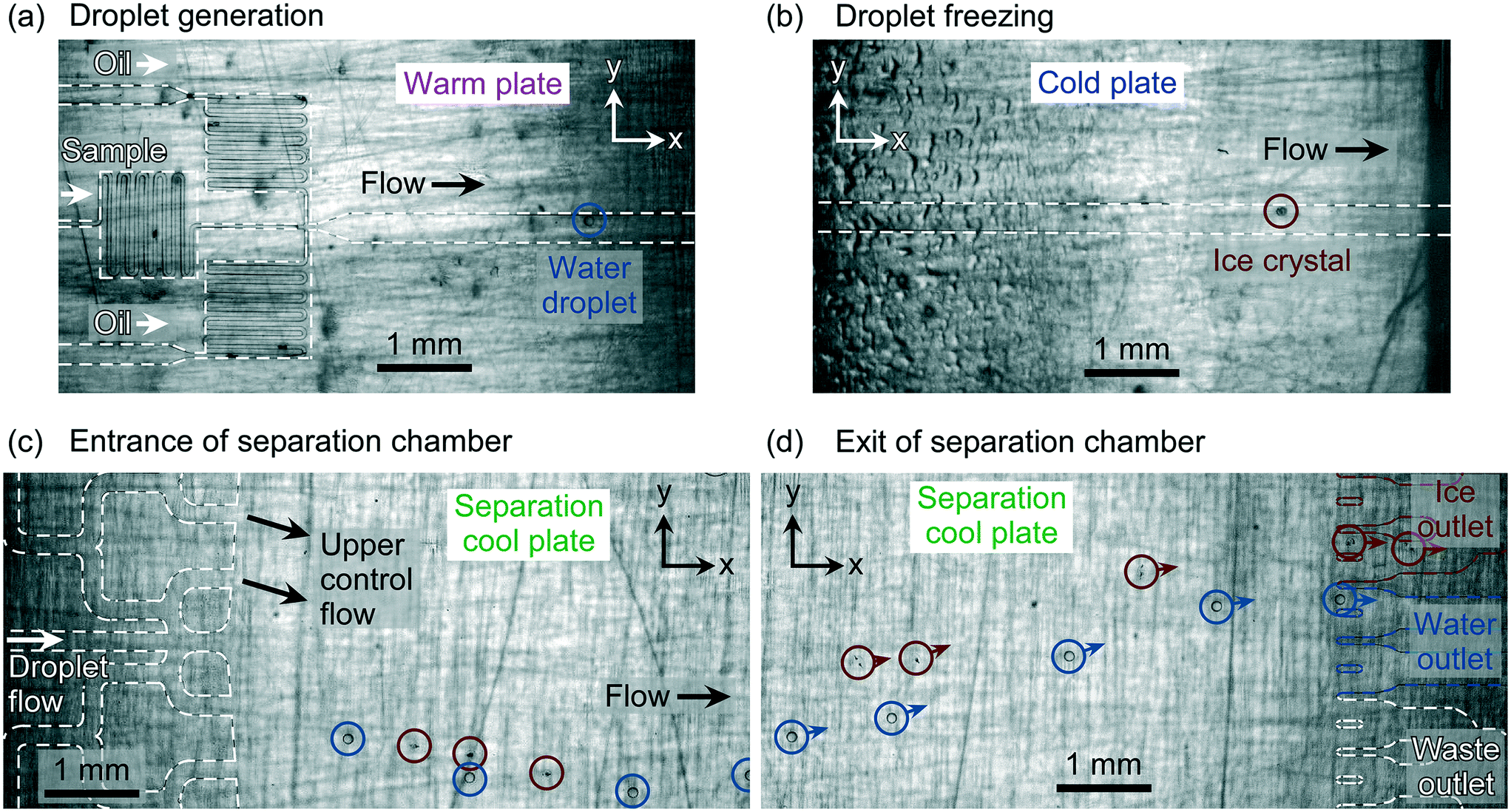 | ||
| Fig. 3 Photographs showing the lifetime of supercooled water droplets (circled in blue) and ice crystals (circled in red) as they (a) are generated at the flow focussing nozzle over a warm plate, (b) pass along the main channel above the cold plate and are potentially frozen (as demonstrated in this case), (c) enter the separation chamber at a temperature slightly below 0 °C and experience a brief downward motion due to the higher applied flow rate of the upper control flow, and (d) traverse the chamber and exit via different outlets depending on whether they are frozen or liquid. | ||
After exiting the cold plate region, the supercooled water droplets and ice crystals continued along the main channel and into the separation chamber. Due to the flow from the upper control channel being greater than that of the main channel, and the lower part of the chamber experiencing no applied flow, the droplets/crystals momentarily travelled downwards in the y-direction immediately upon entering the chamber (Fig. 3c). Within ∼5 mm of entering the 11.6 mm long chamber (in the x-direction), however, the droplets and crystals began to rise in the Novec™ 7500 oil due to the effect of buoyancy, whereupon their deflection direction could be controlled by the applied flow rate of the upper control flow (Fig. 3d).
Water droplet and ice crystal buoyancies
The water droplets that entered the chamber had a measured uhyd velocity in the x-direction of 1667 ± 82 μm s−1, while the ice crystals had a measured uhyd velocity of 1817 ± 106 μm s−1. This demonstrated an increase of 9 ± 2% in uhyd velocity of the ice crystals compared to the water droplets due to the difference in diameter and due to the effect of the ice crystals entering the higher velocity flow stream of the upper control flow.The migration of the droplets/crystals in the y-direction as they creamed in the separation chamber was measured to provide experimental ubuoy values, and these are provided in Table 1 for two identical microfluidic devices, labelled chip A and chip B, with one experimental run performed in the former and three in the latter.
| Experimental run | Chip | Droplets/crystals | u buoy (μm s−1) | Δubuoy (μm s−1) | F buoy (nN) | ΔFbuoy (nN) |
|---|---|---|---|---|---|---|
| 1 | A | Water droplets | 491 ± 23 | 168 ± 45 | 2.7 ± 0.3 | 1.0 ± 0.7 |
| Ice crystals | 659 ± 21 | 3.8 ± 0.3 | ||||
| 2 | B | Water droplets | 528 ± 19 | 107 ± 38 | 3.0 ± 0.3 | 0.7 ± 0.6 |
| Ice crystals | 635 ± 20 | 3.7 ± 0.3 | ||||
| 3 | B | Water droplets | 460 ± 19 | 176 ± 39 | 2.6 ± 0.3 | 1.1 ± 0.6 |
| Ice crystals | 636 ± 20 | 3.7 ± 0.3 | ||||
| 4 | B | Water droplets | 530 ± 11 | 100 ± 22 | 3.0 ± 0.3 | 0.7 ± 0.5 |
| Ice crystals | 630 ± 12 | 3.7 ± 0.3 | ||||
| Average | Water droplets | 502 ± 40 | 138 ± 55 | 2.8 ± 0.6 | 0.9 ± 0.8 | |
| Ice crystals | 640 ± 37 | 3.7 ± 0.6 | ||||
The ice crystals experienced a greater ubuoy velocity in the y-direction as they creamed, an average increase of 28 ± 10% compared to the water droplets, indicating the potential for their separation. The differences in experimental ubuoy between the ice crystals and water droplets, Δubuoy, which directly determines the ability to separate the two, are illustrated in Fig. 4a. Theoretically expected Δubuoy values were calculated from eqn (3), based on the average diameter of the water droplets, and are shown in Fig. 4a as a black line (with the standard deviation shown as a grey band, based on the variation in droplet diameter).
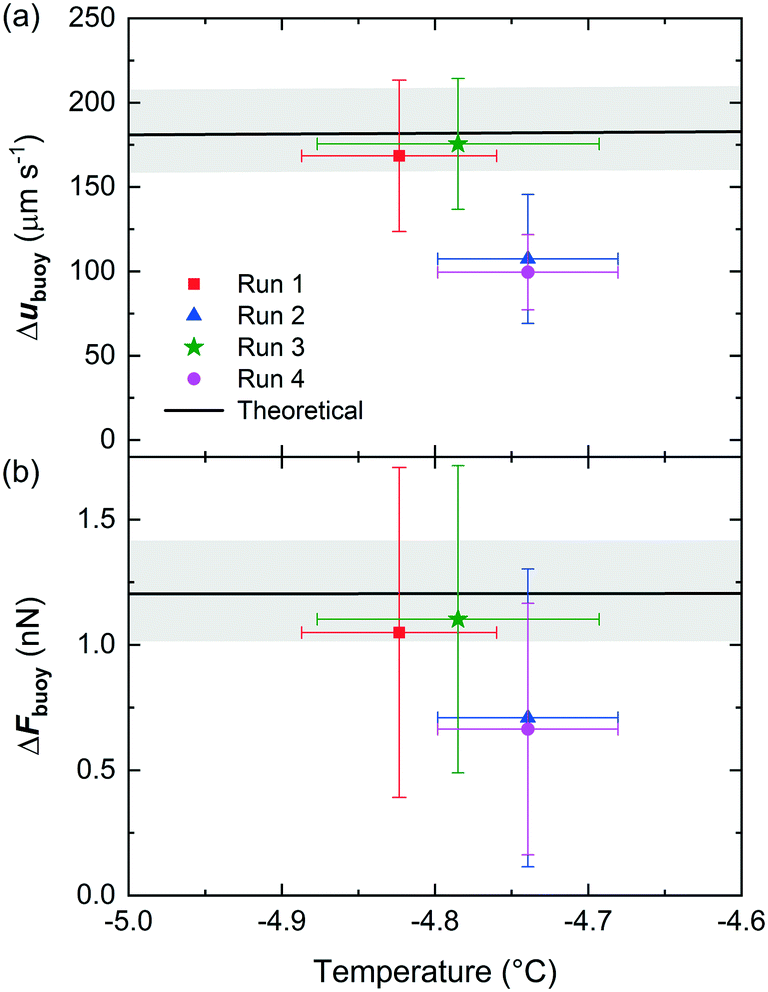 | ||
| Fig. 4 (a) The experimental and theoretically expected differences in ubuoy between ice crystals and water droplets in the microfluidic device. Theoretical values were calculated based on the measured diameters of the water droplets, with the average diameter shown by the black line and the standard deviation represented by the grey band. (b) The corresponding experimental and theoretical values of the differences in Fbuoy between the water droplets and ice crystals. Further details of the experimental runs are provided in Table 1. | ||
The experimental Δubuoy values from chips A and B matched the theory very well in two of the runs, and were slightly lower than expected in two other runs despite an otherwise identical setup. The possible reasons for this will be discussed later. The experimental Fbuoy values were also calculated from the measured ubuoy values using eqn (2) (assuming that Fbuoy = Fvis), using viscosities and densities of supercooled water, ice crystals, and Novec™ 7500 determined as described in ESI† sections 3–6, and the temperature in the separation chamber as discussed earlier. These experimental values are provided in Table 1. As expected given the ubuoy results, the Fbuoy forces were greater on the ice crystals than the water droplets. The differences in Fbuoy between the two are also provided in Table 1 and are plotted in Fig. 4b alongside the theoretically expected ΔFbuoy values. Given that the ΔFbuoy were derived from the Δubuoy values, the same trends are unsurprisingly observed in the former as in the latter.
The lower than expected Δubuoy and ΔFbuoy values that occurred in some experiments likely stemmed as a result of the placement on the cold stage platform. Since the chips were located over the cold plates without the presence of any oil between the two to assist in heat transfer, the temperature in the chamber may have been lower than expected if the contact between the chip and the separation cool plate was poor. This could have occurred since the chip and the cold plates were oriented vertically and so their contact was not assisted by gravity (the chip was held in place with clips connected to the cold stage platform). Furthermore, hydrodynamic lift forces71,72 have not been accounted for in our analyses due to the large height of the chamber when oriented vertically. However, in the event that the setup was not perfectly oriented in the vertical direction and the chip was slightly tilted to differing extents in different experiments, this could introduce effects of lift forces and affect the viscous drag caused by the channel walls.
Some of these effects could be addressed in future iterations of the platform, e.g. by better controlling the orientation and clamping of the chip, and through the use of an oil between the chip and the platform to improve thermal contact. Nevertheless, the results demonstrated that Δubuoy and ΔFbuoy were positive and close to the theoretically expected values, indicating that the separation of frozen and unfrozen droplets was feasible using this technique.
Water droplet and ice crystal separations
The magnitude of Δubuoy and ΔFbuoy between the water droplets and ice crystals is clear (see Fig. 4), with the ice crystals migrating notably faster than the water droplets in the y-direction in Novec™ 7500, and this difference was leveraged to enable their separation in the microfluidic chamber. As the objects travelled through the chamber and separated based on their respective ubuoy velocities, they each exited the chamber via one of the outlet channels (see Fig. 3d and the ESI† for video footage of droplet separation). The numbers of water droplets and ice crystals that exited via the ice crystal outlet system and the water droplet outlet system were counted for a given droplet population, and this was used to determine the separation efficiencies. Results were obtained for three experimental runs (one in chip A and two in chip B), with 105 ± 16 water droplets/ice crystals counted in total per run, and are shown in Fig. 5.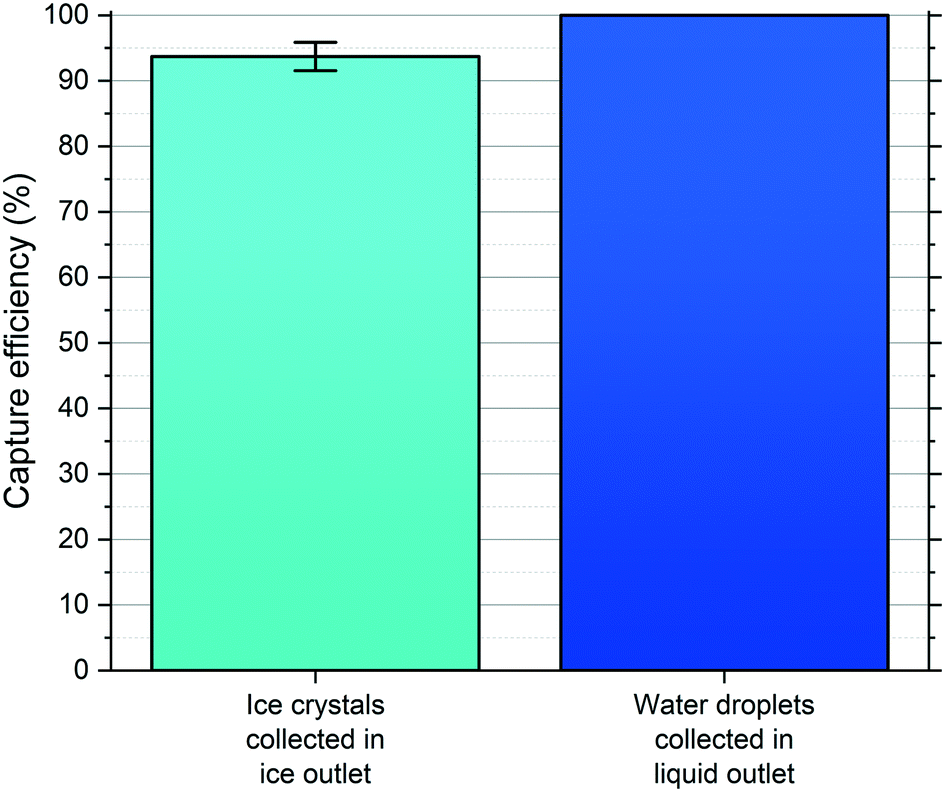 | ||
| Fig. 5 Plot showing the collection efficiencies of ice crystals and water droplets into their respective outlet channels in the microfluidic sorting chamber. The results were generated from three individual experiments, comprising 105 ± 16 water droplets/ice crystals in total per run. | ||
In all cases, only ice crystals were found to exit the separation chamber via the ice outlet (i.e. no water droplets entered this outlet), with a collection efficiency of 94 ± 2% of the total ice crystal population. This meant that, while 100% of water droplets exited via the water outlet, a small number of ice crystals (6 ± 2% of the ice crystal population) also exited the chamber through the water outlet. Therefore, it was successfully demonstrated that ice crystals and water droplets could be separated into different outlets in continuous flow with high efficiency and reproducibility across multiple runs and in two different chips.
Continuous flow separations are affected by temperature, with changes in viscosity affecting not only the ubuoy component of the deflection velocity, udefl, but also the uhyd component.65 It was found that the laboratory temperature could influence the migration of the droplets and crystals since the upper control flow rate into the chamber was so high that the Novec™ 7500 did not have time to fully equilibrate with the plate temperature, hence the temperature at which the fluid was held outside of the chip influenced its temperature inside the chip. This issue was largely eliminated in this particular instance by the use of air conditioning to control the laboratory temperature. In a future update of the chip design, this could be solved via the use of a longer serpentine inlet channel for the upper control flow inlet channel, which would allow a longer equilibration time over the separation cool plate prior to entering the separation chamber.
Several other changes to the chip design and operation could also be implemented to achieve 100% separation efficiency with respect to both water droplets and ice crystals. Several of the features of the current chip design were somewhat superfluous, being a product of testing various mechanisms and flow regimes during the development of the technique. Therefore, future iterations of the design would be far more refined. The extent of the initial separation of the droplets and crystals could be enhanced relatively easily by employing a gradual or sudden expansion into the separation chamber, which would accentuate the difference in ubuoy velocities between the water droplets and ice crystals.19,24 Such improvements would also enable the application of much higher droplet throughputs, since droplet/crystal sorting could potentially still be achieved at much higher flow rates and droplet generation rates. This would help to enable high-throughput downstream processing or analysis, or would allow the rapid collection of enough sample volume for off-chip operations. However, increasing the throughput would also necessitate alterations to the freezing step in order to ensure that droplet cooling rates were not too high.
Another possible means of enhancing the separation could be to adapt the methodology of Kamijo and Derda14 to a microfluidic device. In this scenario, the upper control flow would comprise a low viscosity silicone oil (5 cSt at 25 °C), having a density between that of supercooled water and ice, rather than the Novec™ 7500 Engineered Fluid (ρfluorinated oil > ρwater > ρsilicone oil > ρice). As the droplets and crystals rose to the top of the Novec™ 7500 phase flowing from the main channel, the former would be unable to cross the interface into the silicone oil whilst the latter could cross and continue migrating in the y-direction. However, this strategy may be less simple than it sounds due to the very low theoretical ubuoy velocities the ice crystals would experience in such a medium. Hence, a system comprised fully of Novec™ 7500 may still be the preferable option, particularly given the improvements proposed above. Section 10 of the ESI† provides a more detailed analysis and discussion of the silicone oil strategy as well as its potential benefits and difficulties.
Outlook for the application of water droplet-ice crystal sorting
The density-based sorting of supercooled water droplets and ice crystals in continuous flow has been achieved for the first time in a microfluidic device, and quite possibly in any platform, with high separation efficiency. This technique could aid in a number of applications as outlined in the introduction. In particular, we can see immediate potential for use in two fields, namely low temperature biology9 and atmospheric ice nucleation.2,3 In the former case, it could be envisaged that water droplets containing cells could be exposed to “ideal” freezing conditions (e.g. with ice nucleation triggered at high temperatures to minimise supercooling)1 to ensure a high level of viability amongst the droplet population that froze in those specific conditions. Thereafter, those frozen specimens could be sorted and collected to ensure that only cells with a high likelihood of viability were stored at low temperatures for future use. This might be a useful method for reducing aliquot-to-aliquot variability in viability related to freezing temperature.1,9 While this approach is unlikely to be cost-effective for cells in plentiful supply, it might be useful for high-value cells such as human stem cells, which have potential for use in cancer treatments.75A particularly useful application could be in the selection and concentration of biological ice-nucleating materials that exhibit exceptional ice-nucleating abilities at warmer temperatures, such as certain strains of bacteria, which would enable the subsequent culturing of a highly active form of ice nucleators. A similar approach might also be useful for identifying ice-nucleating materials or organisms in the environment, such as pathogenic ice-nucleating strains of bacteria that can cause frost damage to plants.76 At present, this is achieved through laborious processes,77,78 for example involving repeatedly dividing a sample and selecting the aliquot that has the highest freezing temperature and therefore the most active ice-nucleating entity.79 Also, plating out environmental samples on a growth medium and then testing the resulting colonies for their ice-nucleating activity is often performed, but this approach is only sensitive to organisms amenable to culture.78 In principle, the frozen-unfrozen droplet sorting technique presented here could be used to isolate ice-nucleating biological material, such as bacteria cells, which might then be cultured or the DNA analysed directly for identification.
The sorting technique could prove very powerful in its application to atmospheric ice nucleation. Currently, it can be very difficult to ascertain the identity of atmospheric ice-nucleating particles given their rarity. While it is possible to determine the ice-nucleating activity of a collected aerosol sample using a droplet freezing assay, in which the sample is suspended in droplets of water that are subsequently frozen, it is much harder to determine which component of that sample actually triggered the nucleation event. By sorting frozen and unfrozen droplets whose ice nucleation was triggered at different temperatures, it should be possible to test the two collected outputs to determine which components were present in the frozen population that were not (or were present to a lesser extent) in the unfrozen population. In order to achieve separation of ice-active material from non-ice-active materials it would be necessary to use suspensions which were sufficiently dilute that they have around one insoluble aerosol particle per droplet.
Appropriate analyses on the collected droplet populations for INP identification could include scanning electron microscopy with energy dispersive X-ray spectroscopy (SEM-EDS),59,80–84 DNA analysis,77,85–87 Raman spectroscopy,88 and a variety of other microscopic and spectroscopic techniques used in aerosol particle analysis.82,89–91 The identification and characterisation of the INPs present in the frozen droplet populations would then help to inform on their sources and global transport. It can also be foreseen that such analytical techniques could be translated onto an integrated microfluidic platform that combines the droplet freezing and separation steps with upstream aerosol collection92–96 and downstream analytical processing, potentially yielding a micro total analysis system (μTAS)97,98 for atmospheric INPs. Indeed, there are any number of on-chip microanalytical techniques that could be applied to the chemical or biological analysis of the separated populations.99,100
In addition to sorting droplets for collection, the separation of water droplets and ice crystals into different channels also provides an alternative avenue for determining the fraction frozen of a droplet population at a given temperature, fice(T). Fraction frozen data allows information to be gleaned from both homogeneous ice nucleation (i.e. pure water without the presence of INPs) and heterogeneous ice nucleation experiments. For example, several properties of an ice-nucleating material can be calculated from fice(T), including the ice nuclei concentration in the sample and the ice-active site density, which quantifies a material's effectiveness at nucleating ice. The current strategy of calculating fice(T) in the LOC-NIPI platform involves the counting of droplets in the main channel using a high-speed camera, and determining the number that freeze based on a colour change during a nucleation event.34 While it is possible to automate this detection step it is also somewhat challenging, with the image requiring a clear background and the video file sizes being relatively large. However, sorting the droplets and crystals into separate channels could facilitate a far simpler analysis by incorporating single-point detection systems over the two outlet channels, allowing the simple counting of the number of objects that pass through each. This would require 100% separation efficiency to ensure accurate results but should be achievable given the improvements to the platform detailed earlier, and would eliminate the need for an expensive high-speed camera and image analysis.
Conclusions
We have developed a microfluidic platform, based on our LOC-NIPI ice nucleation analysis system, for the continuous sorting of ice crystals from supercooled water droplets. The ice crystals and water droplets were sorted based on the differences in their buoyancy as they traversed a separation chamber and exited via different outlet channels, with 94 ± 2% separation efficiency achieved. Collection of the sorted populations will, in future, enable the concentration and isolation of the populations, and will allow further analysis to characterise their respective contents.This represents a powerful new technique in ice nucleation that can be used to separate droplets with specific ice-nucleating activity for a range of applications. Its use in cryobiology could allow high levels of viability to be maintained in cryopreserved biological samples by ensuring only the droplets that froze under specific conditions were collected. The ability to isolate and culture highly ice-active biomaterials, such as bacteria, could additionally enable the production of new standards of highly active ice-nucleating agents. In atmospheric science, the technique could facilitate the identification and characterisation of ambient INPs via their separation from a bulk aerosol sample. This could help to revolutionise our understanding of the types, origins, and transport of different types of INPs around the globe.19,24 In addition to improvements in the separation efficiency of the platform, we can also envisage incorporation of upstream aerosol collection and downstream microanalytical techniques to yield an integrated analysis platform for ice nucleation applications.
Conflicts of interest
There are no conflicts to declare.Acknowledgements
The authors thank the European Research Council (ERC; grant no. 648661 MarineIce and 713664 CryoProtect) and the Natural Environment Research Council (NERC; grant no. NE/T00648X/1) for funding. Anthony Windross, Stephen Burgess, and Harri Wyn Williams are thanked for the fabrication of various components of the setup. Alberto Sánchez-Marroquín and Martin I. Daily are thanked for comments on the manuscript.Notes and references
- G. John Morris and E. Acton, Cryobiology, 2013, 66, 85–92 Search PubMed.
- B. J. Murray, D. O'sullivan, J. D. Atkinson and M. E. Webb, Chem. Soc. Rev., 2012, 41, 6519–6554 Search PubMed.
- C. Hoose and O. Möhler, Atmos. Chem. Phys., 2012, 12, 9817–9854 Search PubMed.
- R. Geidobler and G. Winter, Eur. J. Pharm. Biopharm., 2013, 85, 214–222 Search PubMed.
- H. Kiani and D. W. Sun, Trends Food Sci. Technol., 2011, 22, 407–426 Search PubMed.
- H. R. Pruppacher and J. D. Klett, Microphysics of Clouds and Precipitation, Kluwer Academic Publishers, Dordrecht, 1997 Search PubMed.
- T. Koop and B. J. Murray, J. Chem. Phys., 2016, 145, 211915 Search PubMed.
- G. D. Elliott, S. Wang and B. J. Fuller, Cryobiology, 2017, 76, 74–91 Search PubMed.
- M. I. Daily, T. F. Whale, R. Partanen, A. D. Harrison, P. Kilbride, S. Lamb, G. J. Morris, H. M. Picton and B. J. Murray, Cryobiology, 2020, 93, 62–69 Search PubMed.
- Z. A. Kanji, L. A. Ladino, H. Wex, Y. Boose, M. Burkert-Kohn, D. J. Cziczo and M. Krämer, Meteorol. Monogr., 2017, 58, 1.1–1.33 Search PubMed.
- J. Vergara-Temprado, A. K. Miltenberger, K. Furtado, D. P. Grosvenor, B. J. Shipway, A. A. Hill, J. M. Wilkinson, P. R. Field, B. J. Murray and K. S. Carslaw, Proc. Natl. Acad. Sci. U. S. A., 2018, 115, 2687–2692 Search PubMed.
- G. M. Fahy, J. Saur and R. J. Williams, Cryobiology, 1990, 27, 492–510 Search PubMed.
- G. M. Fahy, in Biological Ice Nucleation and Its Applications, ed. R. E. Lee, G. J. Warren and L. V Gusta, APS Press, St. Paul, MN, 1995, p. 331 Search PubMed.
- Y. Kamijo and R. Derda, Langmuir, 2019, 35, 359–364 Search PubMed.
- N. Pamme, Lab Chip, 2007, 7, 1644–1659 Search PubMed.
- A. Lenshof and T. Laurell, Chem. Soc. Rev., 2010, 39, 1203–1217 Search PubMed.
- C. W. Shields IV, C. D. Reyes and G. P. Lopez, Lab Chip, 2015, 15, 1230–1249 Search PubMed.
- H.-D. Xi, H. Zheng, W. Guo, A. M. Gañán-Calvo, Y. Ai, C.-W. Tsao, J. Zhou, W. Li, Y. Huang, N.-T. Nguyen and S. H. Tan, Lab Chip, 2017, 17, 751–771 Search PubMed.
- D. Huh, J. H. Bahng, Y. Ling, H. H. Wei, O. D. Kripfgans, J. B. Fowlkes, J. B. Grotberg and S. Takayama, Anal. Chem., 2007, 79, 1369–1376 Search PubMed.
- D. Sugiyama, Y. Teshima, K. Yamanaka, M. P. Briones-Nagata, M. Maeki, K. Yamashita, M. Takahashi and M. Miyazaki, Anal. Methods, 2014, 6, 308–311 Search PubMed.
- S. R. Springston, M. N. Myers and J. C. Giddings, Anal. Chem., 1987, 59, 344–350 Search PubMed.
- N. Norouzi, H. C. Bhakta and W. H. Grover, PLoS One, 2017, 12, e0180520 Search PubMed.
- A. Winkleman, R. Perez-Castillejos, K. L. Gudiksen, S. T. Phillips, M. Prentiss and G. M. Whitesides, Anal. Chem., 2007, 79, 6542–6550 Search PubMed.
- J. Song, M. Song, T. Kang, D. Kim and L. P. Lee, Biomicrofluidics, 2014, 8, 64108 Search PubMed.
- Y. Xie, Z. Mao, H. Bachman, P. Li, P. Zhang, L. Ren, M. Wu and T. J. Huang, J. Biomech. Eng., 2020, 142, 031005 Search PubMed.
- A. Lenshof, C. Magnusson and T. Laurell, Lab Chip, 2012, 12, 1210–1223 Search PubMed.
- J. Nam, H. Lim, C. Kim, J. Yoon Kang and S. Shin, Biomicrofluidics, 2012, 6, 024120 Search PubMed.
- M. C. Jo and R. Guldiken, Sens. Actuators, A, 2012, 187, 22–28 Search PubMed.
- Y. Ukita, T. Oguro and Y. Takamura, Biomed. Microdevices, 2017, 19, 24 Search PubMed.
- S. Haeberle, T. Brenner, R. Zengerle and J. Ducrée, Lab Chip, 2006, 6, 776–781 Search PubMed.
- O. Strohmeier, M. Keller, F. Schwemmer, S. Zehnle, D. Mark, F. Von Stetten, R. Zengerle and N. Paust, Chem. Soc. Rev., 2015, 44, 6187–6229 Search PubMed.
- T. Morijiri, S. Sunahiro, M. Senaha, M. Yamada and M. Seki, Microfluid. Nanofluid., 2011, 11, 105–110 Search PubMed.
- P. Sajeesh and A. K. Sen, Microfluid. Nanofluid., 2014, 17, 1–52 Search PubMed.
- M. D. Tarn, S. N. F. Sikora, G. C. E. Porter, B. V. Wyld, M. Alayof, N. Reicher, A. D. Harrison, Y. Rudich, J.-u. Shim and B. J. Murray, Lab Chip, 2020, 20, 2889–2910 Search PubMed.
- N. Pamme and A. Manz, Anal. Chem., 2004, 76, 7250–7256 Search PubMed.
- D. E. Raymond, A. Manz and H. M. Widmer, Anal. Chem., 1994, 66, 2858–2865 Search PubMed.
- A. C. Johnson and M. T. Bowser, Lab Chip, 2018, 18, 27–40 Search PubMed.
- J. K. Park, C. D. M. Campos, P. Neužil, L. Abelmann, R. M. Guijt and A. Manz, Lab Chip, 2015, 15, 3495–3502 Search PubMed.
- W. Zhao, R. Cheng, J. R. Miller and L. Mao, Adv. Funct. Mater., 2016, 26, 3916–3932 Search PubMed.
- S. A. Peyman, E. Y. Kwan, O. Margarson, A. Iles and N. Pamme, J. Chromatogr. A, 2009, 1216, 9055–9062 Search PubMed.
- H. Wex, S. Augustin-Bauditz, Y. Boose, C. Budke, J. Curtius, K. Diehl, A. Dreyer, F. Frank, S. Hartmann, N. Hiranuma, E. Jantsch, Z. A. Kanji, A. Kiselev, T. Koop, O. Möhler, D. Niedermeier, B. Nillius, M. Rösch, D. Rose, C. Schmidt, I. Steinke and F. Stratmann, Atmos. Chem. Phys., 2015, 15, 1463–1485 Search PubMed.
- S. S. Hirano and C. D. Upper, Microbiol. Mol. Biol. Rev., 2000, 64, 624–653 Search PubMed.
- C. A. Stan, G. F. Schneider, S. S. Shevkoplyas, M. Hashimoto, M. Ibanescu, B. J. Wiley and G. M. Whitesides, Lab Chip, 2009, 9, 2293–2305 Search PubMed.
- J. F. Edd, K. J. Humphry, D. Irimia, D. A. Weitz and M. Toner, Lab Chip, 2009, 9, 1859–1865 Search PubMed.
- A. E. Sgro and D. T. Chiu, Lab Chip, 2010, 10, 1873–1877 Search PubMed.
- D. Atig, A. Touil, M. Ildefonso, L. Marlin, P. Bouriat and D. Broseta, Chem. Eng. Sci., 2018, 192, 1189–1197 Search PubMed.
- B. Riechers, F. Wittbracht, A. Hütten and T. Koop, Phys. Chem. Chem. Phys., 2013, 15, 5873–5887 Search PubMed.
- C. A. Stan, S. K. Y. Tang, K. J. M. Bishop and G. M. Whitesides, J. Phys. Chem. B, 2011, 115, 1089–1097 Search PubMed.
- A. E. Sgro, P. B. Allen and D. T. Chiu, Anal. Chem., 2007, 79, 4845–4851 Search PubMed.
- L. Weng, S. N. Tessier, K. Smith, J. F. Edd, S. L. Stott and M. Toner, Langmuir, 2016, 32, 9229–9236 Search PubMed.
- L. Weng, A. Swei and M. Toner, Cryobiology, 2018, 84, 91–94 Search PubMed.
- L. Eickhoff, K. Dreischmeier, A. Zipori, V. Sirotinskaya, C. Adar, N. Reicher, I. Braslavsky, Y. Rudich and T. Koop, J. Phys. Chem. Lett., 2019, 10, 966–972 Search PubMed.
- A. Bissoyi, N. Reicher, M. Chasnitsky, S. Arad, T. Koop, Y. Rudich and I. Braslavsky, Biomolecules, 2019, 9, 532 Search PubMed.
- A. Peckhaus, A. Kiselev, T. Hiron, M. Ebert and T. Leisner, Atmos. Chem. Phys., 2016, 16, 11477–11496 Search PubMed.
- N. Reicher, L. Segev and Y. Rudich, Atmos. Meas. Tech., 2018, 11, 233–248 Search PubMed.
- M. D. Tarn, S. N. F. Sikora, G. C. E. Porter, D. O'Sullivan, M. Adams, T. F. Whale, A. D. Harrison, J. Vergara-Temprado, T. W. Wilson, J.-u. Shim and B. J. Murray, Microfluid. Nanofluid., 2018, 22, 52 Search PubMed.
- T. Häusler, L. Witek, L. Felgitsch, R. Hitzenberger and H. Grothe, Atmosphere, 2018, 9, 140 Search PubMed.
- T. Brubaker, M. Polen, P. Cheng, V. Ekambaram, J. Somers, S. L. Anna and R. C. Sullivan, Aerosol Sci. Technol., 2020, 54, 79–93 Search PubMed.
- N. Reicher, C. Budke, L. Eickhoff, S. Raveh-Rubin, I. Kaplan-Ashiri, T. Koop and Y. Rudich, Atmos. Chem. Phys., 2019, 19, 11143–11158 Search PubMed.
- A. Abdelmonem, E. H. G. Backus, N. Hoffmann, M. A. Sánchez, J. D. Cyran, A. Kiselev and M. Bonn, Atmos. Chem. Phys., 2017, 17, 7827–7837 Search PubMed.
- A. Zipori, N. Reicher, Y. Erel, D. Rosenfeld, A. Sandler, D. A. Knopf and Y. Rudich, J. Geophys. Res.: Atmos., 2018, 123, 12762–12777 Search PubMed.
- D. A. Knopf, P. A. Alpert, A. Zipori, N. Reicher and Y. Rudich, npj Clim. Atmos. Sci., 2020, 3, 1–9 Search PubMed.
- J. Happel and H. Brenner, Low Reynolds number hydrodynamics, Noordhoff International Publishing, Leyden, 2nd edn, 1973 Search PubMed.
- Y. Iiguni, M. Suwa and H. Watarai, J. Chromatogr. A, 2004, 1032, 165–171 Search PubMed.
- M. D. Tarn, S. A. Peyman, D. Robert, A. Iles, C. Wilhelm and N. Pamme, J. Magn. Magn. Mater., 2009, 321, 4115–4122 Search PubMed.
- H. Kalman, D. Portnikov, O. G. Gabrieli and N. M. Tripathi, Powder Technol., 2019, 354, 485–495 Search PubMed.
- D. E. Hare and C. M. Sorensen, J. Chem. Phys., 1987, 87, 4840–4845 Search PubMed.
- C. S. Effenhauser, G. J. M. Bruin, A. Paulus and M. Ehrat, Anal. Chem., 1997, 69, 3451–3457 Search PubMed.
- D. C. Duffy, J. C. McDonald, O. J. A. Schueller and G. M. Whitesides, Anal. Chem., 1998, 70, 4974–4984 Search PubMed.
- J. C. McDonald, D. C. Duffy, J. R. Anderson, D. T. Chiu, H. Wu, O. J. A. Schueller and G. M. Whitesides, Electrophoresis, 2000, 21, 27–40 Search PubMed.
- C. A. Stan, A. K. Ellerbee, L. Guglielmini, H. A. Stone and G. M. Whitesides, Lab Chip, 2013, 13, 365–376 Search PubMed.
- C. A. Stan, L. Guglielmini, A. K. Ellerbee, D. Caviezel, H. A. Stone and G. M. Whitesides, Phys. Rev. E: Stat., Nonlinear, Soft Matter Phys., 2011, 84, 036302 Search PubMed.
- M. Polen, E. Lawlis and R. C. Sullivan, J. Geophys. Res.: Atmos., 2016, 121, 11666–11678 Search PubMed.
- S. Wildeman, S. Sterl, C. Sun and D. Lohse, Phys. Rev. Lett., 2017, 118, 084101 Search PubMed.
- D.-T. Chu, T. T. Nguyen, N. L. B. Tien, D.-K. Tran, J.-H. Jeong, P. G. Anh, V. Van Thanh, D. T. Truong and T. C. Dinh, Cells, 2020, 9, 563 Search PubMed.
- S. E. Lindow, D. C. Arny and C. D. Upper, Plant Physiol., 1982, 70, 1084–1089 Search PubMed.
- T. C. J. Hill, B. F. Moffett, P. J. DeMott, D. G. Georgakopoulos, W. L. Stump and G. D. Franc, Appl. Environ. Microbiol., 2014, 80, 1256–1267 Search PubMed.
- T. Šantl-Temkiv, M. Sahyoun, K. Finster, S. Hartmann, S. Augustin-Bauditz, F. Stratmann, H. Wex, T. Clauss, N. W. Nielsen, J. H. Sørensen, U. S. Korsholm, L. Y. Wick and U. G. Karlson, Atmos. Environ., 2015, 109, 105–117 Search PubMed.
- T. C. J. Hill, P. J. Demott, Y. Tobo, J. Fröhlich-Nowoisky, B. F. Moffett, G. D. Franc and S. M. Kreidenweis, Atmos. Chem. Phys., 2016, 16, 7195–7211 Search PubMed.
- A. Sanchez-Marroquin, D. H. P. Hedges, M. Hiscock, S. T. Parker, P. D. Rosenberg, J. Trembath, R. Walshaw, I. T. Burke, J. B. McQuaid and B. J. Murray, Atmos. Meas. Tech., 2019, 12, 5741–5763 Search PubMed.
- C. S. McCluskey, P. J. DeMott, A. J. Prenni, E. J. T. Levin, G. R. McMeeking, A. P. Sullivan, T. C. J. Hill, S. Nakao, C. M. Carrico and S. M. Kreidenweis, J. Geophys. Res.: Atmos., 2014, 119, 10458–10470 Search PubMed.
- A. P. Ault and J. L. Axson, Anal. Chem., 2017, 89, 430–452 Search PubMed.
- A. Kiselev, F. Bachmann, P. Pedevilla, S. J. Cox, A. Michaelides, D. Gerthsen and T. Leisner, Science, 2017, 355, 367–371 Search PubMed.
- B. Wang, D. A. Knopf, S. China, B. W. Arey, T. H. Harder, M. K. Gilles and A. Laskin, Phys. Chem. Chem. Phys., 2016, 18, 29721–29731 Search PubMed.
- J. A. Huffman, A. J. Prenni, P. J. Demott, C. Pöhlker, R. H. Mason, N. H. Robinson, J. Fröhlich-Nowoisky, Y. Tobo, V. R. Després, E. Garcia, D. J. Gochis, E. Harris, I. Müller-Germann, C. Ruzene, B. Schmer, B. Sinha, D. A. Day, M. O. Andreae, J. L. Jimenez, M. Gallagher, S. M. Kreidenweis, A. K. Bertram and U. Pöschl, Atmos. Chem. Phys., 2013, 13, 6151–6164 Search PubMed.
- T. Šantl-Temkiv, R. Lange, D. Beddows, U. Rauter, S. Pilgaard, M. Dall'osto, N. Gunde-Cimerman, A. Massling and H. Wex, Environ. Sci. Technol., 2019, 53, 10580–10590 Search PubMed.
- E. Garcia, T. C. J. Hill, A. J. Prenni, P. J. DeMott, G. D. Franc and S. M. Kreidenweis, J. Geophys. Res.: Atmos., 2012, 117, D18 Search PubMed.
- A. Iwata and A. Matsuki, Atmos. Chem. Phys., 2018, 18, 1785–1804 Search PubMed.
- P. A. Ariya, J. Sun, N. A. Eltouny, E. D. Hudson, C. T. Hayes and G. Kos, Int. Rev. Phys. Chem., 2009, 28, 1–32 Search PubMed.
- C. E. Kolb and D. R. Worsnop, Annu. Rev. Phys. Chem., 2012, 63, 471–491 Search PubMed.
- J. Laskin, A. Laskin and S. A. Nizkorodov, Anal. Chem., 2018, 90, 166–189 Search PubMed.
- A. R. Metcalf, S. Narayan and C. S. Dutcher, Aerosol Sci. Technol., 2018, 52, 310–329 Search PubMed.
- I. Mirzaee, M. Song, M. Charmchi and H. Sun, Lab Chip, 2016, 16, 2254–2264 Search PubMed.
- S. D. Noblitt, G. S. Lewis, Y. Liu, S. V. Hering, J. L. Collett and C. S. Henry, Anal. Chem., 2009, 81, 10029–10037 Search PubMed.
- B. Damit, Aerosol Sci. Technol., 2017, 51, 488–500 Search PubMed.
- W. Jing, W. Zhao, S. Liu, L. Li, C. T. Tsai, X. Fan, W. Wu, J. Li, X. Yang and G. Sui, Anal. Chem., 2013, 85, 5255–5262 Search PubMed.
- D. R. Reyes, D. Iossifidis, P. A. Auroux and A. Manz, Anal. Chem., 2002, 74, 2623–2636 Search PubMed.
- D. E. W. Patabadige, S. Jia, J. Sibbitts, J. Sadeghi, K. Sellens and C. T. Culbertson, Anal. Chem., 2016, 88, 320–338 Search PubMed.
- M. Yew, Y. Ren, K. S. Koh, C. Sun and C. Snape, Global Challenges, 2019, 3, 1800060 Search PubMed.
- Y. Song, B. Lin, T. Tian, X. Xu, W. Wang, Q. Ruan, J. Guo, Z. Zhu and C. Yang, Anal. Chem., 2019, 91, 388–404 Search PubMed.
- G. C. E. Porter, S. N. F. Sikora, J.-u. Shim, B. J. Murray and M. D. Tarn, Data for ‘On-chip density-based sorting of ice crystals and supercooled water droplets in continuous flow’, University of Leeds. [Dataset], https://doi.org/10.5518/848, 2020.
Footnotes |
| † Electronic supplementary information (ESI) available: Parameterisations are provided that relate to the equations used in this paper. Further details are given on the setup and operation of the platform. A video showing the continuous flow separation of ice crystals and supercooled water droplets is provided. An analysis of water droplet and ice crystal behaviour in a low viscosity silicone oil is presented. See DOI: 10.1039/d0lc00690d |
| ‡ The data sets for this paper and videos of the experimental runs are available in the University of Leeds Data Repository (https://doi.org/10.5518/848; Porter et al. 2020).101 |
| This journal is © The Royal Society of Chemistry 2020 |