
 Open Access Article
 This Open Access Article is licensed under a
 Creative Commons Attribution 3.0 Unported Licence
Nanocrystal synthesis, μfluidic sample dilution and direct extraction of single emission linewidths in continuous flow†
Ioannis
Lignos‡
 ab,
Hendrik
Utzat‡
b,
Moungi G.
Bawendi
*b and
Klavs F.
Jensen
*a
ab,
Hendrik
Utzat‡
b,
Moungi G.
Bawendi
*b and
Klavs F.
Jensen
*a
aDepartment of Chemical Engineering, Massachusetts Institute of Technology, 77 Massachusetts Avenue, Cambridge, MA 02139, USA. E-mail: kfjensen@mit.edu
bDepartment of Chemistry, Massachusetts Institute of Technology, 77 Massachusetts Avenue, Cambridge, MA 02139, USA. E-mail: mgb@mit.edu
First published on 30th April 2020
Abstract
The rational design of semiconductor nanocrystal populations requires control of their emission linewidths, which are dictated by interparticle inhomogeneities and single-nanocrystal spectral linewidths. To date, research efforts have concentrated on minimizing the ensemble emission linewidths, however there is little knowledge about the synthetic parameters dictating single-nanocrystal linewidths. In this direction, we present a flow-based system coupled with an optical interferometry setup for the extraction of single nanocrystal properties. The platform has the ability to synthesize nanocrystals at high temperature <300 °C, adjust the particle concentration after synthesis and extract ensemble-averaged single nanocrystal emission linewidths using flow photon-correlation Fourier spectroscopy.
Semiconductor nanocrystals (NCs) (or quantum dots – QDs) have received enormous attention as luminescent materials for biological1 and optoelectronic applications.2,3 This is mainly driven by their unique and synthetically tuneable optical and electronic properties.4,5 Although particle size dictates the band energy of the NCs, sample inhomogeneity and the emission linewidths of individual NCs dictate the resulting spectral linewidths.6 To date, all synthetic methodologies are focused on minimizing the ensemble emission linewidth, without considering the effect of single-NC linewidths. This is largely due to the lack of efficient experimental and analytical tools for uncovering the determining synthetic parameters governing single-NC emission linewidths without the effect of post-synthetic methodologies.7 Establishing a direct link between synthetic parameters and single-NC emission linewidths will be essential for understanding the mechanisms governing inhomogeneous broadening and thus further promote NC-based applications.
Herein, we demonstrate a flow-based reaction and dilution system coupled with a confocal fluorescence single-molecule microscope that allows extraction of ensemble-averaged single NC emission linewidths using flow photon-correlation Fourier spectroscopy (F-PCFS). The F-PCFS setup allows for an investigation of the effect of reaction parameters such as (reaction time, temperature, molar ratios of precursors) on ensemble and single dot emission spectra of the synthesized NCs in their native solution, thus shifting the current paradigm of reaction optimization from ensemble to the single-dot level. A single molecule technique based on solution photon correlation Fourier spectroscopy (S-PCFS) has been established previously in our group.8,9 S-PCFS combines fluorescence correlation spectroscopy (FCS) of single emitters in solution in a Hanbury-Brown–Twiss geometry with Fourier spectroscopy to extract single and ensemble spectral emission linewidths from solution, thus completely eliminating the selection bias of conventional single-emitter fluorescence spectroscopy.10 In S-PCFS, at optical-path length differences spanning the coherence length of the emission, the degree of spectral coherence is encoded in the intensity-cross-correlation function compiled from photon-pairs detected at the output arms of the interferometer. In the frequency domain, the observable of this measurement is the spectral correlation p(ζ,τ), the auto-correlation of the spectra compiled from photon pairs with temporal separation τ. Since the decay of FCS traces is due to photon-pairs from the same single emitter, p(ζ,τ) can be parsed into the ensemble and ensemble averaged single NC spectral correlation pensemble(ζ,τ) and psingle(ζ,τ), respectively. Because of the short exposure times of individual NCs and comparatively low intensity excitation, S-PCFS is beneficial for the study of sensitive samples that tend to blinking and photobleaching. This ability to interrogate photo-labile samples has recently been demonstrated by measuring emission linewidths of lead halide perovskite NCs.11 Accordingly, single-NC spectroscopy and interferometric analysis can uncover the basic processes governing spectral properties like single particle linewidths and degree of inhomogeneous broadening.12–14 However, linking such spectroscopic tools with more sophisticated synthetic configurations would potentially accelerate the optimized synthesis of NC populations. Flow reactor systems have received considerable attention since they allow for rapid and controllable thermal and mass transfer and thus define an ideal medium for preparing NCs with well-defined morphology and physicochemical characteristics.7,15–17 In particular, flow reactor systems with integrated detection modalities are able to reassess standard synthetic approaches and to rapidly optimize reaction conditions, while providing a unique environment for elucidating reaction kinetics.18–38
In this study, we explore the potential of the proposed technique for the in situ determination of single and ensemble emission spectra of a model reaction system, CdSe NCs, while varying the temperature (240–300 °C) and molar ratios of Cd and Se precursors. An important aspect of the proposed methodology is that droplet-based microfluidic reactors cannot be integrated with the photon-correlation spectroscopic technique, because the droplet flow would dominate the correlation function, causing misinterpretations of the acquired data. In addition, the intensity correlation function would not provide information for single NCs traversing the confocal volume, but only for the frequency of droplet formation. These aspects present fundamental limitations to the use of droplets in intensity-correlation measurements to access single-particle properties in flow. For this reason, a continuous flow microfluidic setup was designed for the synthesis, dilution and characterization of CdSe NCs.
The flow platform is comprised of three units: the reaction system for the synthesis of NCs, a tube-based microfluidic ladder for in-flow dilution of the synthesized NCs and the F-PCFS setup for the detection of single and ensemble spectra. The flow reactor system is shown schematically in Fig. 1a. It was made of polyether ether ketone (PEEK) tubing (OD 1/16 inch, ID 0.02 inch, IDEX) which was wrapped around a heated aluminium block.
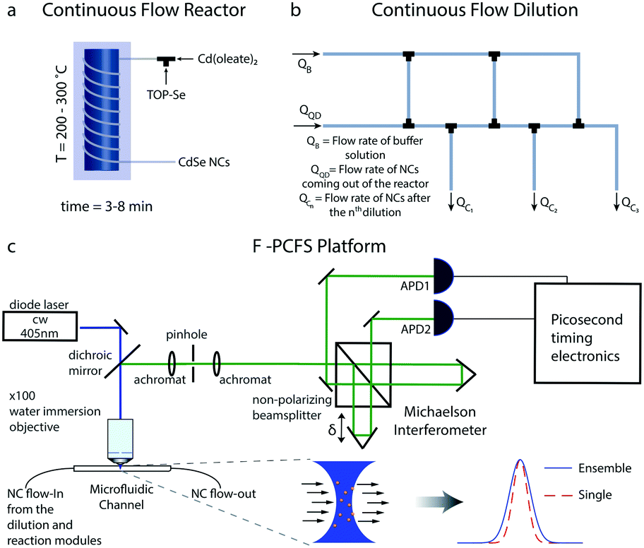 | ||
| Fig. 1 (a) The continuous tube-based flow reactor system. The synthesized NCs are then transferred to the dilution unit. (b) Tube-based dilution ladder scheme. The flow rates of each part of the microfluidic ladder can be controlled by the fluidic resistances (length and size of the microfluidic channels). The diluted NCs, from QC1–QC3 (depending on the number of dilutions), are then promoted into the fused silica capillary for the F-PCFS measurements. (c) Schematic of the F-PCFS setup. The fluorescence from the synthesized NCs flowing through a small focal volume through an interferometer. With correlation analysis of the intensities at both outputs, the spectral correlation function for the average single particle can be distinguished from the spectral correlation function for the ensemble. | ||
A tube-based microfluidic reactor can provide flexibility and simplicity over operating temperatures, back-pressure, dilution, cost and subsequent integration with advanced single-molecule tools. Syringe pumps (Harvard apparatus) were used for injecting the precursor solutions (in the case of the synthesis of CdSe NCs, we used trioctylphosphine selenide (TOP-Se) and cadmium oleate (Cd(Oleate)2)). The different units of the platform were connected with standard PEEK unions and microTee connectors (IDEX). In a typical synthesis, the flow rates of cadmium and selenium precursors were set in the range of 2–30 μL min−1, with a residence time of 3–8 min.
Apart from the reaction system, a robust dilution scheme was needed to be developed to ensure that the focal volume in the microfluidic channel would have 100–10![[thin space (1/6-em)]](https://www.rsc.org/images/entities/char_2009.gif) 000 particles per femtoliter, a typical occupancy used in FCS experiments.39,40 For this purpose, we developed a serial dilution configuration (dilution ladder) for providing any desired dilution depending on the initial concentration of precursor solutions (Fig. 2b). The flow network is similar to an electric circuit with the micro-channels acting as flow resistances for controlling all outlet flow rates.41 The dilution ladder was comprised of perfluoroalkoxy (PFA) tubing of 0.01 and 0.02 inch (depending on the flow resistance and dilution ratios) and commercial fluidic connector assemblies and connections with the other parts of the platform. To regulate the flow rates of the outlet channels we use adjustable resistances, specifically the tubing diameter and length.
000 particles per femtoliter, a typical occupancy used in FCS experiments.39,40 For this purpose, we developed a serial dilution configuration (dilution ladder) for providing any desired dilution depending on the initial concentration of precursor solutions (Fig. 2b). The flow network is similar to an electric circuit with the micro-channels acting as flow resistances for controlling all outlet flow rates.41 The dilution ladder was comprised of perfluoroalkoxy (PFA) tubing of 0.01 and 0.02 inch (depending on the flow resistance and dilution ratios) and commercial fluidic connector assemblies and connections with the other parts of the platform. To regulate the flow rates of the outlet channels we use adjustable resistances, specifically the tubing diameter and length.
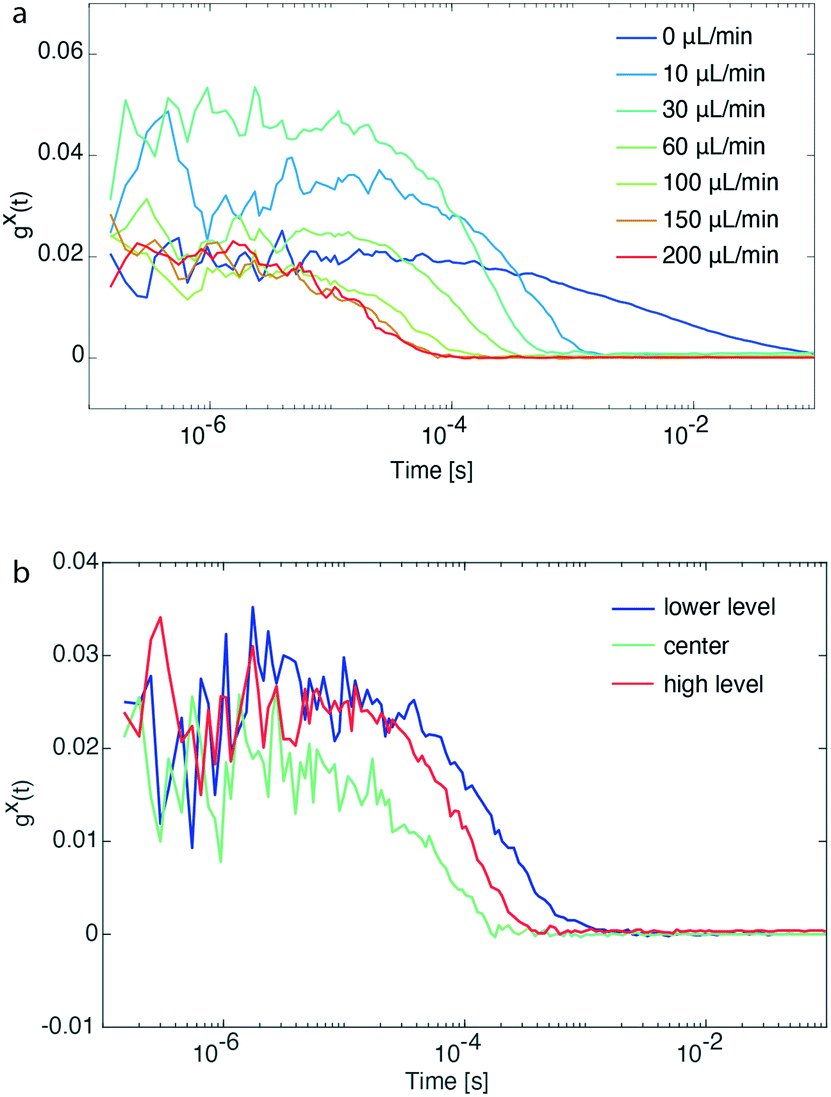 | ||
| Fig. 2 (a) FCS traces of a pre-synthesized and diluted solution of CdSe/CdS QDs emitting at ∼600 nm at different flow rates. Identification of the flow rate limits during an F-PCFS measurement. (b) FCS traces of the same sample solution at different z-positions of the objective. Calibration of the setup based on the flow profile of a continuous flow format. | ||
The advantages of such a scheme compared to step-wise additions of buffer solution (QB) into the outlet of the microfluidic channel are (i) linear concentration profiles using minimal amounts of buffer solution, and (ii) the flow rate of the outlet channel (QC,3) connected to the detection module being relatively low (10–30 μL min−1) for acquiring better FCS traces. In addition, depending on the synthesized NCs, different protocols can be developed for the generation of buffer solutions suitable for the in-flow dilution of NCs without altering their spectral properties, including their emission linewidth and the position of their emission maximum. The integrity of the particles under high dilutions was checked before the F-PCFS measurements by recording ensemble emission spectra using a highly sensitive cooled Electron Multiplying Charge Coupled Device (EMCCD) camera after dispersion with a monochromator (both Princeton Instruments).
FCS has already been combined with microfluidic systems mainly for characterizing the flow profile in microfluidic channels.42–45 In the current study, for the detection of the flowing NCs, it is important that the microfluidic channel positioned on top of a water-immersion objective (N. A. = 0.9) has a wall thickness of no more than ∼100 μm so that the laser beam (c. w. laser at 405 nm) can be focused at the center of the microfluidic channel. For this purpose, a fused silica capillary, with 360 μm outer diameter and 250 μm inner diameter, was selected. By removing the coating of the fused silica capillary by burning it, it became possible to detect the flowing NCs with a 100× water immersion objective extracting FCS traces with good signal-to-noise.
An important task before the synthesis and detection of single-NC spectral linewidths was to evaluate flow rate and channel position limits. For this reason, pre-synthesized CdSe/CdS QDs emitting at ∼600 nm and diluted prior to the flow experiment were loaded in a glass syringe and transferred into the microfluidic channel. Flow rates of the particle solution were varied between 10 and 200 μL min−1, whereas a control experiment with stationary particles was also performed (0 μL min−1). Fig. 2a shows that FCS traces with good signal-to-noise ratio could be recorded for flow rates up to 200 μL min−1 and at the same time the diffusion times of particles passing by the focal volume was shortened from 1 s to 0.1 ms. After identifying the maximum operational flow rate, we also evaluated the behavior of FCS traces while altering the z-position of the objective.
As shown in Fig. 2b, the concentration of CdSe/CdS QDs at the center of the microfluidic channel is higher than its upper and lower level (number of particles is inversely proportional to the y-intercept, gx(t), of the intensity cross-correlation function). This is explained by the parabolic flow profile, which is characteristic for a continuous flow format, where the flow packets at the center of a channel are travelling faster (increasing particle occupancy) than those close to the walls. For all experiments performed, the z-position of the objective was set at the center of the microfluidic channel for the following reasons: (a) higher fluorescence intensity due to higher concentration of particles, (b) prevention of recording of FCS traces of potential aggregated particles accumulating onto the channel walls, and (c) reaction time of particle formation determined by particles travelling at the center of the microfluidic channel.
The formation of CdSe QDs served to demonstrate applicability of F-PCFS for probing single and ensemble spectra. CdSe QDs were prepared using Cd(OA)2 and TOP-Se. The initial precursor concentrations were in the range of 1–10 mM and 2–20 mM for the Cd(OA)2 and TOP-Se solutions, respectively. With this initial concentration of precursors, the series of the necessary in-line dilutions was set to one or two.
A crucial aspect during an F-PCFS measurement is to ensure flow and particle stability before and after dilution of the synthesized particles. Potential flow or particle instabilities will impact the (a) photoluminescence spectrum (PL) intensity and (b) the amplitude of the FCS trace due to concentration changes over time in the focal volume or the formation of aggregates. The latter will induce rapid increase in the amplitude of the cross-correlation function but also changes over the diffusion times over the course of the experiment, introducing artifacts in the F-PCFS measurement.
To acquire F-PCFS measurements, the interferometer was adjusted to discrete path-length differences δ0 (typically 60–90 μm) spanning the coherence length of the emission. At each δ0, the path-length difference is periodically dithered over a multiple of the emission wavelength (∼1020 nm) with a frequency of ∼0.05 to 0.1 Hz. The photon-arrival times at the output arms of the interferometer were recorded with picosecond photon counting equipment (Picoquant Hydraharp). Computation of the intensity correlation (FCS) functions at each stage position was performed with home-built MATLAB software in post-processing (see ESI† for details). A typical F-PCFS measurement (meaning one set of synthetic conditions) lasts between 30–90 min, corresponding to 20 s–1 min of integration at each state position, depending on the photon-count-rate and particle occupancy, which further determine the signal-to-noise ratio of the FCS trace.
In this direction, we first evaluated the formation of CdSe NCs synthesized at 250 °C. As shown in the contour plot of Fig. 3a, the PL maximum position remains constant for a period of 42 min (see Fig. S1 and S2† for additional flow stability tests) at 2.14 meV and essentially invariant maximum intensity, demonstrating the excellent temporal stability of the reaction and dilution units. Small variations of PL maximum intensity are attributed to fluctuations in the temperature control unit (±2 °C).
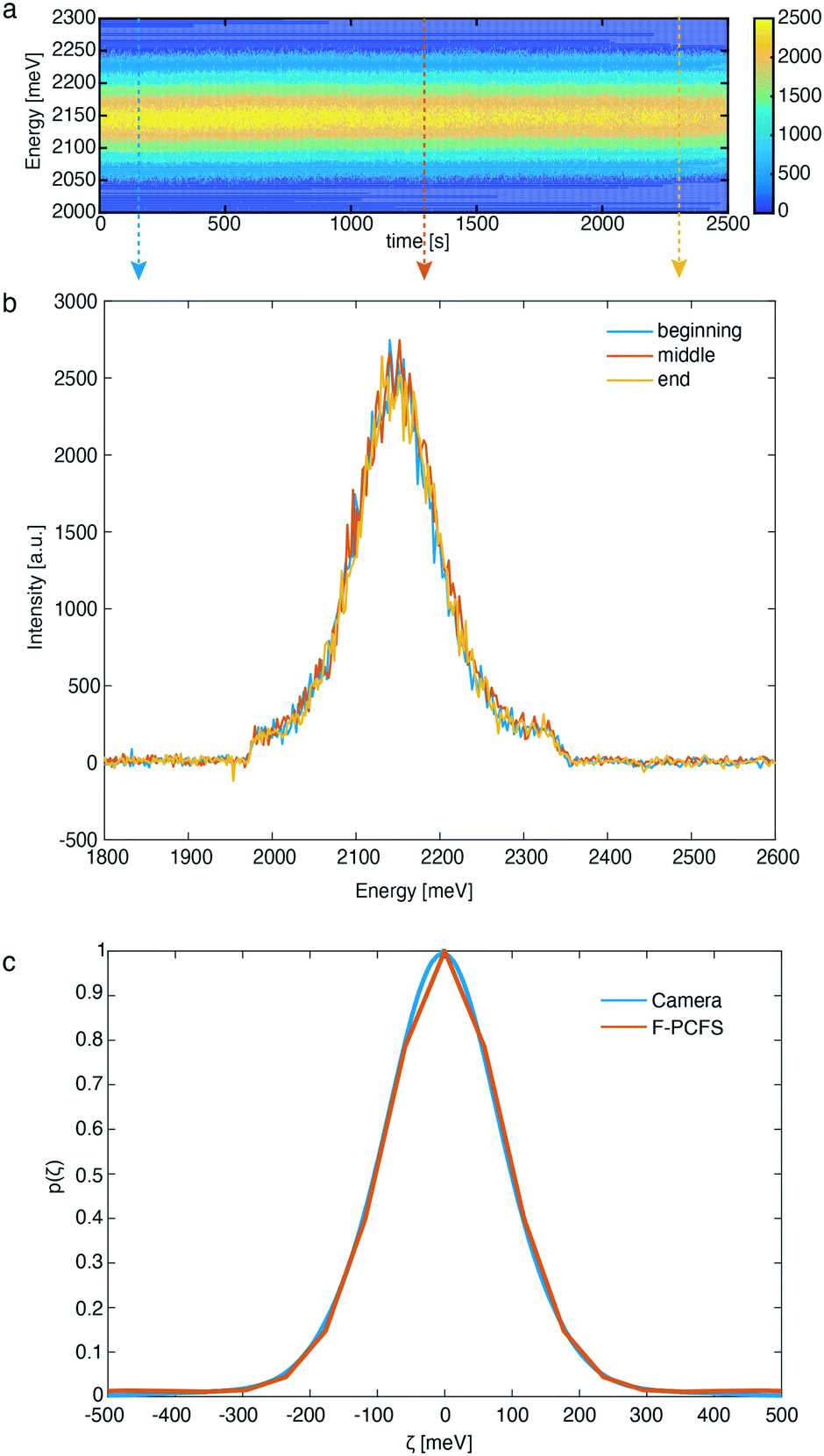 | ||
| Fig. 3 (a) Contour plot of PL spectra for CdSe QDs synthesized in our microfluidic reactor over 42 minutes of continuous operation. The reaction time was 3.5 min, temperature was fixed at 250 °C and Se:Cd = 1.5, QQD:QB = 1. (b) PL spectra of CdSe QDs extracted from the contour plot at the beginning, middle and end of the F-PCFS measurement. The arrows in Fig. 3a represent the operational times for Fig. 3b. (c) PL spectrum and ensemble spectral correlation for the synthesized CdSe QDs recorded with the CCD camera and extracted from the F-PCFS measurement, respectively. | ||
In addition, Fig. 3b, demonstrates the PL spectra at 3 different times of the experiment extracted from the contour plot, which further confirm that the shape and peak position of the PL spectra do not change over this period. Optical long and short pass filters were used to spectrally isolate the band-edge emission peak from the NCs, free from any parasitic fluorescence originating from the Cd(OA)2 buffer solution (see ESI† for the preparation) or lower-energy trap emission that would obscure the F-PCFS measurement. Unlike in conventional Fourier spectroscopy, which measures the spectrum, the observable of PCFS is the spectral correlation, the auto-correlation of the spectrum without the absolute phase information. We ensure validity of the setup-alignment by comparing the ensemble spectral correlation p(ζ) extracted from F-PCFS with the auto-correlation of the ensemble spectrum recorded in situ with the EMCCD camera (Fig. 3c). In addition, based on the autocorrelation traces for the F-PCFS measurements, it is apparent that the average occupation of particles in the focal volume is high (g2(t) = 1.001–1.01, Fig. S3†). The total PCFS interferogram is the linear combination of the ensemble average single particle interferogram and the ensemble interferogram. Therefore, Fig. S4,† which shows a decay of the single NC interferogram on timescales of the FCS decay curves, indicates a real single NC interferogram contribution even at high particle occupancies. Last, another crucial aspect is to ensure that the ensemble component does not have a τ dependence because it is determined by the statistics of different particles entering and exiting the focal volume.10 Fig. S5† illustrates the invariance of the single NC spectral correlation with selection of τ, which further confirms our data analysis.
From extracting the spectral correlation at photon-lag-times smaller than the particle dwell-time, we can extract the single particle spectral correlation (psingle(ζ,τ)), which – due to fast particle exchange – is a measure of the ensemble averaged single particle emission linewidth. Fig. 4 compares psingle(ζ,τ) to pensemble(ζ,τ) 2.21 eV – CdSe QDs (Fig. 4a) and 2.15 eV – CdSe synthesized at 250 °C and 270 °C, respectively (Fig. 4b). The linewidth of the underlying ensemble averaged single CdSe QDs and ensemble linewidth was evaluated by inferring an effective spectral linewidth (ESL), an effective full width half maximum (fwhm), from Gaussian fits to the spectral correlations as performed previously.10,11Fig. 4 indicates that the ensemble and averaged single linewidths are similar for both 2.21 eV – CdSe QDs (ESLensemble ∼ 163 meV, ESLsingle ∼ 153 meV) and 2.15 eV – CdSe QDs (ESLensemble ∼ 140 meV, ESLsingle ∼ 127 meV) (see Fig. S6–S9† for additional F-PCFS measurements and F-PCFS reproducibility). The minimal difference between ensemble and single emission linewidths is explained by the fact that the ensemble emission is the convolution of the intrinsic linewidth and the polydispersity distribution. For intrinsically broad single NC samples, the convolution is dominated by the intrinsic linewidth and the effect of polydispersity minimal. In that case, inhomogeneous broadening is minor. In general, higher temperatures lead to a red-shift of PL spectra, which indicates the formation of NCs with larger sizes. In addition, the corresponding F-PCFS measurements indicate that ESLsingle gets narrower at higher temperatures and for the same molar ratio of precursors (Fig. 4). This is in accordance with previous studies, which demonstrated that single-NC linewidth decreases nearly monotonically with increasing particle size.12 The overall increased single-NC linewidth observed herein can also be attributed to surface imperfections that have been shown to contribute dramatically to the single particle linewidth owing to the stronger exciton-phonon coupling to surface modes.46,47
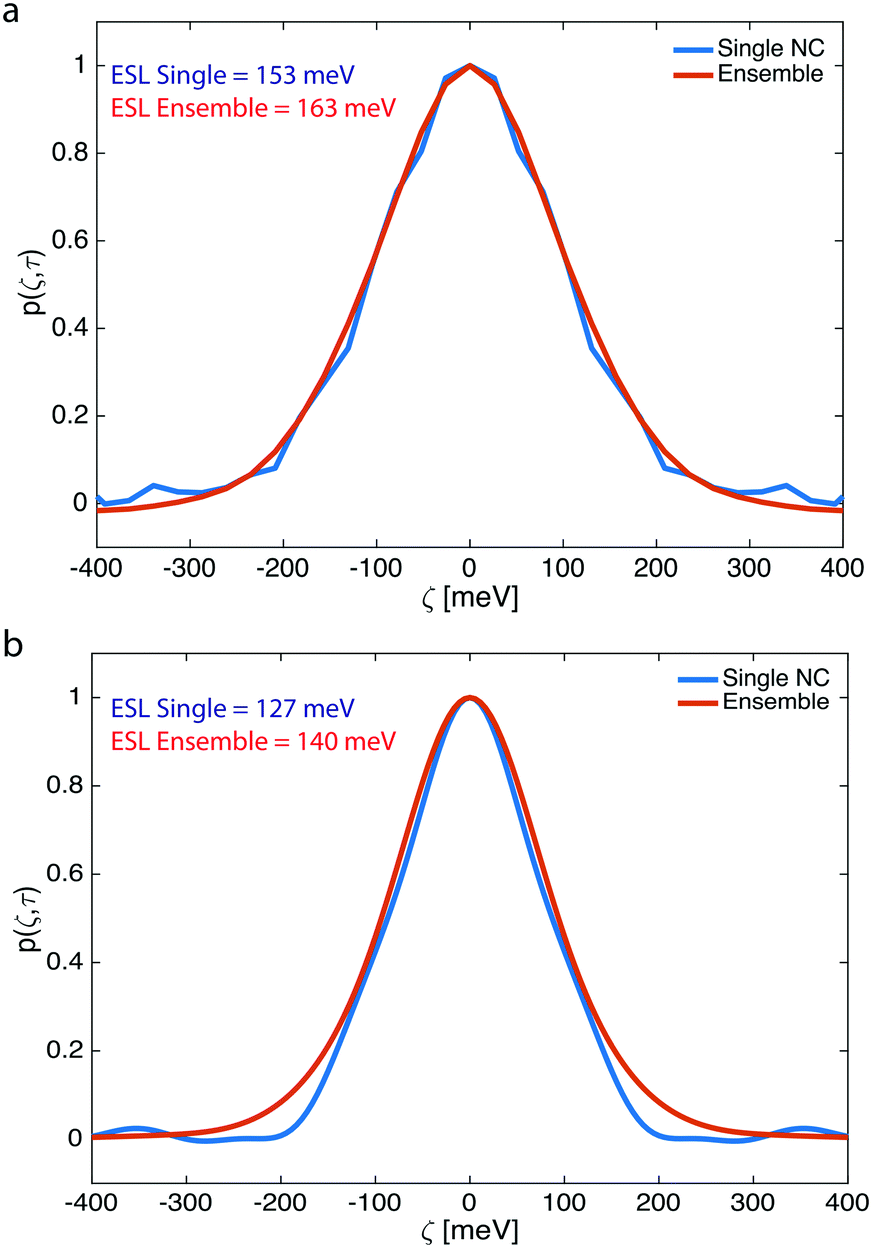 | ||
| Fig. 4 Ensemble averaged single NC (blue line) and ensemble spectral correlation (red line) for CdSe QDs synthesized at (a) 250 °C and (b) 270 °C. We find that inhomogeneous broadening is almost negligible for the as-synthesized and non-purified CdSe QDs. | ||
The single NC linewidths observed herein are broad compared to high-quality samples prepared via hot-injection synthesis, which show single particle linewidths of ∼80–90 meV (after particle purification).12 The broad linewidth measured here may indicate that freshly synthesized NCs exhibit broader ensemble averaged single particle linewidth than NC ensembles, which have been purified via precipitation and re-dispersion. This widely-used purification procedure may remove sub-populations of poor optical quality NCs from the ensemble. In addition, in the current methodology the initial concentration of precursors was 10 times lower than that of hot-injection synthesis, which could further affect the single and ensemble emission linewidths (the F-PCFS measurements presented in the ESI† were conducted using higher concentrations, such as 10 mM Cd and 20 mM Se).
Additional S-PCFS measurements were conducted to compare the ESLsingle of crude and purified samples. Fig. S10–S15† compare psingle(ζ,τ) to pensemble(ζ,τ) of various crude and purified samples synthesized in the microfluidic reactor. Table S1† summarizes the results of the S-PCFS analysis, where it is clear that in most cases particle purification has a direct effect on ESLsingle, which drops to ∼100 meV, and it is similar to what our group has previously reported for core-only CdSe particles.12 To further ensure that there is no contribution of QD flow in our measurements, we performed S-PCFS and F-PCFS measurements to extract the ESLsingle and ESLensemble of a crude solution. The crude solution was synthesized in the microfluidic reactor, diluted offline and finally transferred either in a capillary for S-PCFS or in a syringe for F-PCFS. Comparing Fig. S12 and S16,† it is apparent that ESLsingle and ESLensemble are similar for both stationery and flow experiments, which further confirms that ESLsingle and ESLensemble are not affected by QD flow.
Conclusions
In summary, we demonstrated for the first time a microfluidic platform for the synthesis, in-line dilution and extraction of single and ensemble NC spectra in flow. The flow setup can operate at various flow conditions, temperatures and reaction times allowing for an investigation on product characteristics down to the single NC level. As a proof of principle study, we indicated the effectiveness of the platform on extracting single NC and ensemble spectra of CdSe NCs synthesized in situ and at different operating temperatures and molar ratios. Broadly, we demonstrate the feasibility of coupling interferometry, FCS, and microfluidic synthesis platforms to allow analysis of single emitter linewidths and optical heterogeneities as a function of synthetic parameters. We anticipate this study to be the starting point for further technique development, including fast-reaction feedback control by using inhomogeneous broadening as a minimization parameter.Conflicts of interest
There are no conflicts to declare.Acknowledgements
I. L. was supported by a Swiss National Science Foundation Grant (SNSF) P2EZP2_172127 as well as the National Science Foundation through grant EECS-1449291 (microfluidic reactor design and construction, synthetic procedures and optical measurements). HU was funded by the Department of Energy, office of basic energy sciences, Division of Materials Sciences and Engineering (award no. DE-FG02-07ER46456) (optical set-up design and construction and optical measurements).References
- P. D. Howes, R. Chandrawati and M. M. Stevens, Science, 2014, 346, 1247390 CrossRef PubMed
.
- M. V. Kovalenko, Nat. Nanotechnol., 2015, 10, 994–997 CrossRef CAS PubMed
- C. R. Kagan, E. Lifshitz, E. H. Sargent and D. V. Talapin, Science, 2016, 353, aac5523 CrossRef PubMed
- C. B. Murray, C. R. Kagan and M. G. Bawendi, Annu. Rev. Mater. Sci., 2000, 30, 545–610 CrossRef CAS
- D. V. Talapin, J.-S. Lee, M. V. Kovalenko and E. V. Shevchenko, Chem. Rev., 2010, 110, 389–458 CrossRef CAS PubMed
- J. Cui, A. P. Beyler, T. S. Bischof, M. W. B. Wilson and M. G. Bawendi, Chem. Soc. Rev., 2014, 43, 1287–1310 RSC
- I. Lignos, R. Maceiczyk and A. J. deMello, Acc. Chem. Res., 2017, 50, 1248–1257 CrossRef CAS PubMed
- L. F. Marshall, J. Cui, X. Brokmann and M. G. Bawendi, Phys. Rev. Lett., 2010, 105, 053005 CrossRef PubMed
- X. Brokmann, M. Bawendi, L. Coolen and J.-P. Hermier, Opt. Express, 2006, 14, 6333 CrossRef PubMed
- J. Cui, A. P. Beyler, L. F. Marshall, O. Chen, D. K. Harris, D. D. Wanger, X. Brokmann and M. G. Bawendi, Nat. Chem., 2013, 5, 602–606 CrossRef CAS PubMed
- H. Utzat, K. E. Shulenberger, O. B. Achorn, M. Nasilowski, T. S. Sinclair and M. G. Bawendi, Nano Lett., 2017, 17, 6838–6846 CrossRef CAS PubMed
- J. Cui, A. P. Beyler, I. Coropceanu, L. Cleary, T. R. Avila, Y. Chen, J. M. Cordero, S. L. Heathcote, D. K. Harris, O. Chen, J. Cao and M. G. Bawendi, Nano Lett., 2016, 16, 289–296 CrossRef CAS PubMed
- J. R. Caram, S. N. Bertram, H. Utzat, W. R. Hess, J. A. Carr, T. S. Bischof, A. P. Beyler, M. W. B. Wilson and M. G. Bawendi, Nano Lett., 2016, 16, 6070–6077 CrossRef CAS PubMed
- S. N. Bertram, B. Spokoyny, D. Franke, J. R. Caram, J. J. Yoo, R. P. Murphy, M. E. Grein and M. G. Bawendi, ACS Nano, 2019, 13, 1042–1049 CAS
- T. W. Phillips, I. G. Lignos, R. M. Maceiczyk, A. J. deMello and J. C. deMello, Lab Chip, 2014, 14, 3172–3180 RSC
- L.-J. Pan, J.-W. Tu, H.-T. Ma, Y.-J. Yang, Z.-Q. Tian, D.-W. Pang and Z.-L. Zhang, Lab Chip, 2018, 18, 41–56 RSC
- G. Niu, A. Ruditskiy, M. Vara and Y. Xia, Chem. Soc. Rev., 2015, 44, 5806–5820 RSC
- S. Krishnadasan, J. Tovilla, R. Vilar, A. J. deMello and J. C. deMello, J. Mater. Chem., 2004, 14, 2655 RSC
- E. M. Chan, A. P. Alivisatos and R. A. Mathies, J. Am. Chem. Soc., 2005, 127, 13854–13861 CrossRef CAS PubMed
- C. L. Kuyper, K. L. Budzinski, R. M. Lorenz and D. T. Chiu, J. Am. Chem. Soc., 2006, 128, 730–731 CrossRef CAS PubMed
- J. Polte, R. Erler, A. F. Thünemann, S. Sokolov, T. T. Ahner, K. Rademann, F. Emmerling and R. Kraehnert, ACS Nano, 2010, 4, 1076–1082 CrossRef CAS PubMed
- A. M. Nightingale, S. H. Krishnadasan, D. Berhanu, X. Niu, C. Drury, R. McIntyre, E. Valsami-Jones and J. C. deMello, Lab Chip, 2011, 11, 1221–1227 RSC
- I. Lignos, L. Protesescu, S. Stavrakis, L. Piveteau, M. J. Speirs, M. A. Loi, M. V. Kovalenko and A. J. deMello, Chem. Mater., 2014, 26, 2975–2982 CrossRef CAS
- M. Abolhasani, C. W. Coley, L. Xie, O. Chen, M. G. Bawendi and K. F. Jensen, Chem. Mater., 2015, 27, 6131–6138 CrossRef CAS
- A. M. Karim, N. Al Hasan, S. Ivanov, S. Siefert, R. T. Kelly, N. G. Hallfors, A. Benavidez, L. Kovarik, A. Jenkins, R. E. Winans and A. K. Datye, J. Phys. Chem. C, 2015, 119, 13257–13267 CrossRef
- I. Lignos, S. Stavrakis, A. Kilaj and A. J. deMello, Small, 2015, 11, 4009–4017 CrossRef CAS PubMed
- M. Jiao, J. Zeng, L. Jing, C. Liu and M. Gao, Chem. Mater., 2015, 27, 1299–1305 CrossRef CAS
- R. Baber, L. Mazzei, N. T. K. Thanh and A. Gavriilidis, RSC Adv., 2015, 5, 95585–95591 RSC
- I. Lignos, S. Stavrakis, G. Nedelcu, L. Protesescu, A. J. deMello and M. V. Kovalenko, Nano Lett., 2016, 16, 1869–1877 CrossRef CAS PubMed
- R. W. Epps, K. C. Felton, C. W. Coley and M. Abolhasani, Lab Chip, 2017, 17, 4040–4047 RSC
- R. M. Maceiczyk, D. Hess, F. W. Y. Chiu, S. Stavrakis and A. J. deMello, Lab Chip, 2017, 17, 3654–3663 RSC
- Y. Shen, M. Abolhasani, Y. Chen, L. Xie, L. Yang, C. W. Coley, M. G. Bawendi and K. F. Jensen, Angew. Chem., Int. Ed., 2017, 56, 16333–16337 CrossRef CAS PubMed
- G. Tofighi, H. Lichtenberg, J. Pesek, T. L. Sheppard, W. Wang, L. Schöttner, G. Rinke, R. Dittmeyer and J.-D. Grunwaldt, React. Chem. Eng., 2017, 2, 876–884 RSC
- I. Lignos, L. Protesescu, D. B. Emiroglu, R. Maceiczyk, S. Schneider, M. V. Kovalenko and A. J. DeMello, Nano Lett., 2018, 18, 1246–1252 CAS
- J. Baek, Y. Shen, I. Lignos, M. G. Bawendi and K. F. Jensen, Angew. Chem., Int. Ed., 2018, 57, 10915–10918 CrossRef CAS PubMed
- K. Abdel-Latif, R. W. Epps, C. B. Kerr, C. M. Papa, F. N. Castellano and M. Abolhasani, Adv. Funct. Mater., 2019, 29, 1900712 Search PubMed
- E. J. Guidelli, I. Lignos, J. J. Yoo, M. Lusardi, M. G. Bawendi, O. Baffa and K. F. Jensen, Chem. Mater., 2018, 30, 8562–8570 CAS
- I. Lignos, R. M. Maceiczyk, M. V. Kovalenko and S. Stavrakis, Chem. Mater., 2020, 32, 27–37 CrossRef CAS
- D. Magde, E. Elson and W. W. Webb, Phys. Rev. Lett., 1972, 29, 705–708 CrossRef CAS
- R. Rigler, Ü. Mets, J. Widengren and P. Kask, Eur. Biophys. J., 1993, 22, 169–175 CrossRef CAS
- C. Kim, K. Lee, J. H. Kim, K. S. Shin, K.-J. Lee, T. S. Kim and J. Y. Kang, Lab Chip, 2008, 8, 473 RSC
- P. C. Brister, K. K. Kuricheti, V. Buschmann and K. D. Weston, Lab Chip, 2005, 5, 785–791 RSC
- E. L. Elson, Biophys. J., 2011, 101, 2855–2870 CrossRef CAS PubMed
- M. Gösch, H. Blom, J. Holm, T. Heino and R. Rigler, Anal. Chem., 2000, 72, 3260–3265 CrossRef PubMed
- E. Zamir, C. Frey, M. Weiss, S. Antona, J. P. Frohnmayer, J.-W. Janiesch, I. Platzman and J. P. Spatz, Anal. Chem., 2017, 89, 11672–11678 CAS
- A. D. Dukes, P. C. Samson, J. D. Keene, L. M. Davis, J. P. Wikswo and S. J. Rosenthal, J. Phys. Chem. A, 2011, 115, 4076–4081 CAS
- C. Lin, D. F. Kelley, M. Rico and A. M. Kelley, ACS Nano, 2014, 8, 3928–3938 CrossRef CAS PubMed
Footnotes |
| † Electronic supplementary information (ESI) available. See DOI: 10.1039/d0lc00213e |
| ‡ These authors contributed equally. |
| This journal is © The Royal Society of Chemistry 2020 |