
 Open Access Article
 This Open Access Article is licensed under a Creative Commons Attribution-Non Commercial 3.0 Unported Licence
Colorimetric absorbance mapping and quantitation on paper-based analytical devices†
Yoshiki
Soda
,
Kye J.
Robinson
 ,
Thomas J.
Cherubini
and
Eric
Bakker
*
,
Thomas J.
Cherubini
and
Eric
Bakker
*
Department of Inorganic and Analytical Chemistry, University of Geneva, Quai Ernest-Ansermet 30, CH-1211 Geneva, Switzerland. E-mail: Eric.Bakker@unige.ch
First published on 10th March 2020
Abstract
A wide range of microfluidic paper-based analytical devices (μPADs) have been developed in the last decade. Despite this, the quality of colorimetric analysis has not substantially improved as the data is vulnerable to heterogeneous color distribution (e.g., coffee ring effects), non-uniform shapes of colored detection area, and noise from the underlying paper structure. These limitations are here addressed by a colorimetric method to quantify freely discharged dye on paper substrate, without the need for a defined channel or hydrophobic barrier. For accurate quantification, colorimetric absorbance values are calculated for each pixel based on the recorded RGB values and noise from the paper structure eliminated, to extract accurate absorbance information at the pixel level. Total analyte quantity is then calculated through the conversion of absorbance values into quantity values for each pixel followed by integration across the entire image. The resulting quantity is shown to be independent of the shape of the applied colored dye spot, with a cross, circle or rod shape all giving the same quantity information. The approach is applied to a capillary-based potassium-selective sensor, where the sample solution is loaded with the dye thioflavin T (ThT) obtained by quantitative exchange with K+ in a sensing capillary, which is discharged onto a bare paper substrate without any channels. The resulting dye quantity is successfully obtained by flatbed scanner and smartphone. The successful automated computation of colorimetric data on μPADs will help realize simpler paper-based assay and reaction systems that should be more applicable to addressing real world analytical problems.
Introduction
As microfluidic paper-based analytical devices (μPADs) have been improved over the years,1 low-cost and simple-to-use devices for various analytes such as ions,2–6 biomolecules and markers7–15 and small molecules12 have been developed. For this reason, paper-based analytical devices are recognized as a simpler variant of lab-on-a-chip devices with higher user-friendliness.The expense for this simplicity in device design is that the rational understanding of the reaction occurring on the device is often ignored, partly because conventional quantitative methods such as spectrophotometry are not readily applicable on paper. While there has been an effort to measure transmittance on paper, it requires lab-scaled instrumentation to apply an intense incident light to transmit sufficient signal through the paper matrix.16–20 More invasive methods include reaction systems such as saturating the device in oil.21 Nevertheless, researchers still reply on such methods of limited accuracy because of the surface structure of the paper that introduces scattering and noise. In addition, there is no established method to precisely quantify dyes on paper, and so colorimetric analysis on μPADs has conventionally been quite vulnerable to color heterogeneity on paper. More importantly, the relationship between color and quantitative information has been unclear.
We have recently demonstrated the correlation of RGB-based absorbance values calculated from the spectra of dye and color on the image data both in aqueous solution phase and on paper substrate after characterizing the spectral sensitivity of the imaging device.22 It has been clarified that RGB-based absorbance, coined colorimetric absorbance, follows Beer's law in the aqueous phase but not typically on paper substrate. Absorbance behavior on paper may deviate exponentially from the ideal Beer's law, and in this case may be predictable with an exponential function.
Provided that the relationship between the amount of dye and colorimetric absorbance value is known, one may obtain quantity information of the dye in a predetermined area, even in a single pixel, of the image data. If this is successful, one may integrate the pixel-level quantity information over the image area of interest to obtain the total quantity of dye on paper. This may then solve most of the quantification problems on μPADs listed above. In addition, the single pixel analysis may allow one to map the absorbance on paper substrate in an elegant, non-invasive manner.
Here, a method for the single-pixel level dye quantification on paper is introduced, using thioflavin T (ThT) and neutral red (NR) as model dyes. The colorimetric absorbance values in the red, green and blue channels were calculated for each pixel by identifying and selecting the colored pixels by computation. The apparent noise from the paper roughness was eliminated by using all 3 channels to formulate simultaneous equations for dye and paper contributions. These equations were then solved for each pixel separating the pristine dye absorbance from paper noise. This allows one to obtain appropriate absorbance values in the most responsive channel that are largely independent of the paper structure. Once the function that correlates colorimetric absorbance to dye quantity in a pixel is established, the 2D absorbance image is converted to a quantity map that allows one to obtain the total quantity of the target dye. This approach is confirmed to be independent of the shape of the color spot for both ThT, which has very simple absorbance spectra responding only in blue channel, and NR, which produces a substantial response in all three channels,22 indicating the broadly applicable nature of this quantification method.
This quantification method is then applied to a capillary-based K+-selective optical assay utilizing ThT. In this assay an ion-selective membrane containing K+ ionophore, cation-exchanger and cationic ThT as indicator dye exchanges K+ from the sample with ThT in the membrane. In turn, the exchanged ThT is dispensed onto a bare paper substrate without any hydrophobic barrier, and is successfully quantified by the approach introduced here.
Experimental section
Fabrication of colored paper-based spots by ThT and NR solution
Spots were patterned by a hydrophobic barrier on the paper substrate with a procedure introduced earlier but with Advantec 5C filter paper.4 In this work, the bottom side of the wax-patterned paper substrate was laminated with an A4 sized laminate film. At this time, the upper side of the paper substrate was covered with a baking sheet to prevent the detachment of the laminate.For ThT spot test, 10, 25, 50, 75, 100, 200, 300, 400, 500, 600, 700, 970, 1313 mg L−1 ThT solutions were prepared, 8 μL of them was dropped on the paper spots and left at room temperature for drying. Similarly, 10, 25, 50, 75, 100, 200, 300, 400, 500, 600, 700, 900, 1300, 1500 mg L−1 NR solutions were prepared and spotted in the same way.
Discharge of ThT and NR solution on bare paper
To an A4 sized sheet of Advantec 5C filter paper a larger piece of baking sheet was added to cover the top side of the filter paper and prevent the adhesion of a lamination film. These sheets were placed between a lamination film and laminated using a GMP MyJOY-12 laminator on its highest temperature setting (10). 10 μL of 100, 200, 300, 400, 500, 600, 700 mg L−1 ThT or NR samples were discharged on the bottom-laminated bare paper in various shapes and left until dry. Following this, image data of this ThT-colored paper was obtained using a Canosan 9000f Mark II flatbed scanner.Fabrication of capillary-based K+-selective optical sensor and the quantification of K+ on bare paper
16 mg of PVC and 32 mg of bis(2-ethylhexyl)sebacate (DOS) were dissolved in 3 mL of THF. 0.40 mL of this mixture was used to dissolve 2.61 mg of valinomycin (4.87 mmol kg−1), 1.65 mg of sodium tetrakis[3,5-bis(trifluoromethyl)phenyl]borate (NaTFPB; 3.50 mmol kg−1), and 0.53 mg of thioflavin T (3.13 mmol kg−1) to obtain a near-exhaustive membrane response in a 1–4 mM K+ sample. The fabrication of the capillary sensor was carried out by solvent-casting this mixture as reported previously.2 1, 2, 3, 4, 5, 6, 10 mM K+ aqueous sample solution were prepared. 10 μL of each sample was aspirated into the capillary-based sensor and discharged on bare paper after 3 min incubation. And in turn, image data of this ThT-colored paper was obtained by the flatbed scanner.Image data acquisition by smartphone
A colored paper sample was placed in a black box equipped with LED light source on the inner side of its roof which was ultimately covered by 4 sheets of filter paper. For image data acquisition, Adobe® Photoshop Lightroom, professional mode was used in iPhone XR, with the following parameters, Exp: 0, Sec A1/24, ISO: 25, WB: AWB, focus: auto.Computation method for dye quantitation
RGB-based absorbance (colorimetric absorbance)
RGB values of image data are directly related to the light intensity entering the camera detector, although it undergoes filtration by the RGB channel sensitivity.22 Therefore, the negative logarithm of the relative recorded intensities of R, G or B channels represents the so-called “colorimetric absorbance”22 value as shown eqn (1).ARGB = −γ![[thin space (1/6-em)]](https://www.rsc.org/images/entities/char_2009.gif) log (RGB/R0G0B0) log (RGB/R0G0B0) | (1) |
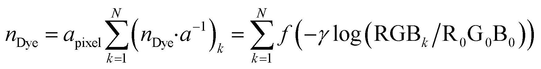
The purpose of this work is to quantify a dye deposited onto bare paper without any channel that would confine the color spot, and apply the methodology to chemical sensing by using only colorimetric image data. A major obstacle is the heterogeneity of dye distribution on the paper substrate. Fig. 1a shows an example of freely dropped dye thioflavin T (ThT) on bare filter paper, where ThT is spread more or less heterogeneously.
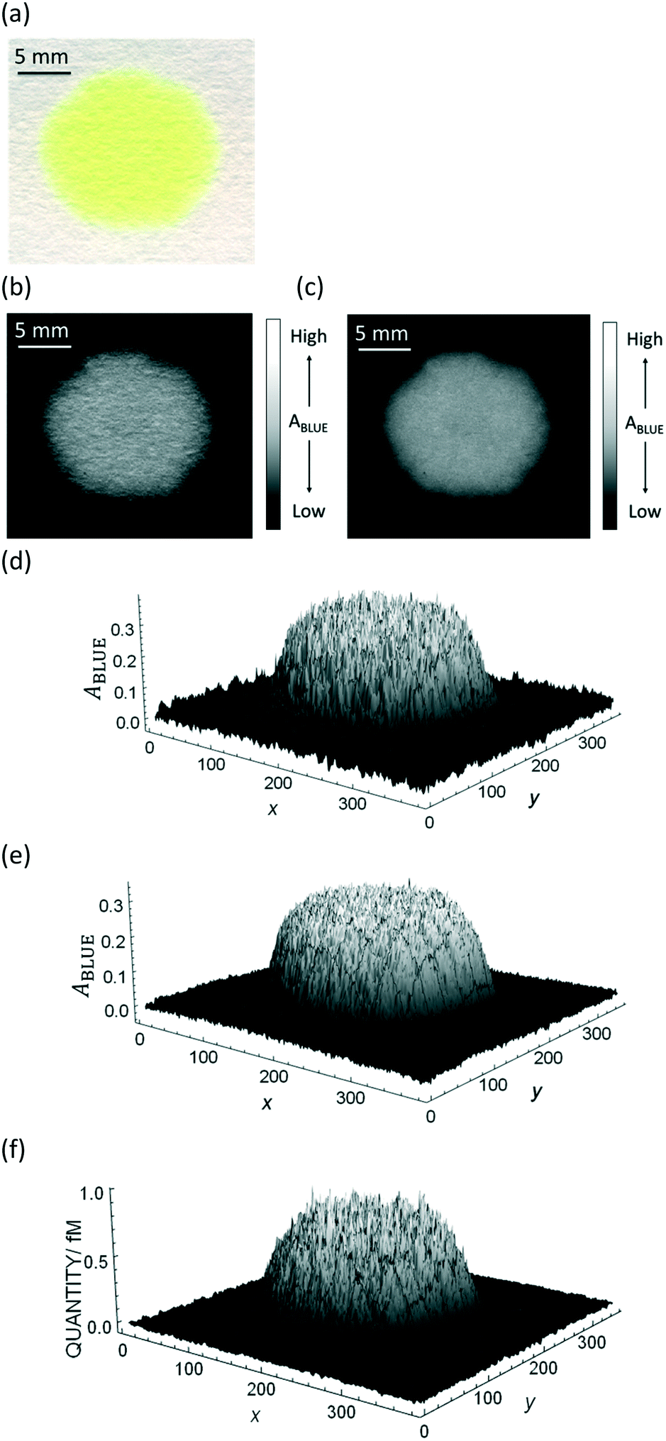 | ||
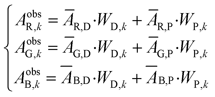
| Fig. 1 Example of an image data conversion into absorbance mapping and quantification of dye using ThT as example dye. (a) Shows the original image data prepared by dropping 10 μL of 700 mg L−1 ThT solution on a bare paper that is bottom laminated; (b) represents absorbance mapping figure calculated by the extracted blue value and eqn (1) (see eqn (6) for the calculation of background blue value), containing paper noise; (c) is also an absorbance mapping figure from the same image data but after elimination of the noise from the paper structure; (d) and (e) are the 3D plots of absorbance values before and after noise cancelling, and (f) is the 3D plot showing the ThT quantity profile on the paper substrate calculated based on eqn (S1)† and the noise canceled absorbance data in (e). | ||
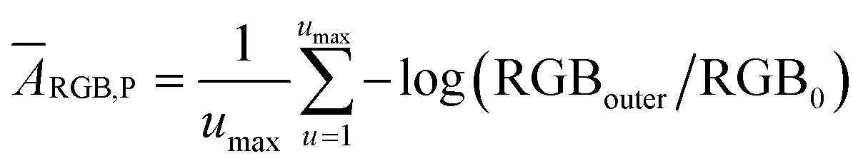
Summary of the quantification method and mathematical interpretation
The quantification approach is to compute the amount of dye in a minute area of the image and to subsequently integrate it over the entire image. According to a recently published relationship between colorimetric absorbance and dye quantity,22 it should be possible to quantify ThT in an extremely small area based on the colorimetric absorbance. The minimum unit of an image data is a single pixel that contains a discrete RGB data point. Hence, eqn (1) may be applied to acquire colorimetric absorbance for each pixel to obtain absorbance information for the whole image. For best results, one must also eliminate the noise from the roughness of the paper surface, which will be separately discussed further below.We have previously introduced the “deterioration ratio” to relate the absorbance on the paper substrate to dye concentration, shown here as eqn (2).22
| ApaperRGB = dr([Dye])·AidealRGB([Dye]) = f([Dye]) | (2) |
| A = ε(mol−1 L cm−1)·[Dye](mol dm3)·l(dm) = ε(mol−1 L cm−1)·nDye(mol)·a−1(dm−2) | (3) |
| ApaperRGB = f(nDye·a−1) or nDye·a−1 = f(ApaperRGB) | (4) |
The deterioration ratio of ThT was obtained as in the previous report with a flatbed scanner.22 Pi-stacking of dyes is thought to cause this deviation from Beer’s law which helps explain why the deterioration ratio depends on dye solubility. As it is challenging to quantitatively predict dye solubility and its effect on colorimetric absorbance, a fitting equation is used here. Fig. S1† shows the fitted curve and its equation to acquire a pixelated quantity (=nDye·a−1) for each pixel. The sum of pixelated dye quantity over the image will then give the total quantity of dye on the paper substrate:
 | (5) |
Absorbance calculation and automatic recognition of main and background channels
To carry out the absorbance calculation by eqn (1), an appropriate background intensity value is first determined. As the experimental image data contains color from the dye of interest, the identification and extraction of the non-colored area should be conducted. Colored pixels were first eliminated by identifying pixels that are above a determined threshold range and turning these values to 0, making them black. Following the elimination of colored pixels, the average background value was calculated by dividing the sum of all blue values by the number of non-colored pixels below the threshold range. This process may be formulated as eqn (6).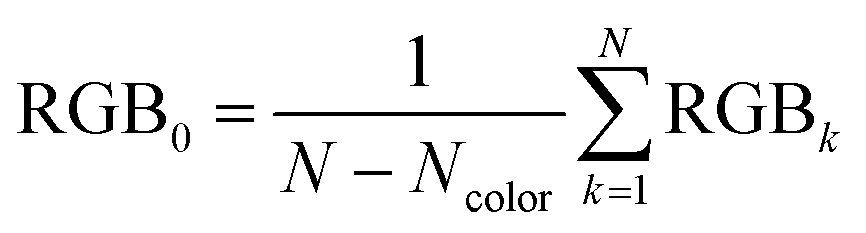 | (6) |
Separation of dye absorbance from the paper substrate noise
The notable noise originating from the roughness of the paper surface as seen in Fig. 1b has been an important limitation of paper-based analytical devices, and according to our knowledge no work on μPADs has overcome this issue. Here, the noise is eliminated by the following computation method.As images are obtained with three color channels (see Fig. S3a–c†), signal originating from both the dye and paper can be unmixed by using their distinct absorbance profiles.23 By carrying out this unmixing after conversion of pixel values to colorimetric absorbance we can avoid the difficulties associated with pixel values. The absorbance signal for each pixel can be represented by the following set of equations (eqn (7)):
 | (7) |
 | (8) |
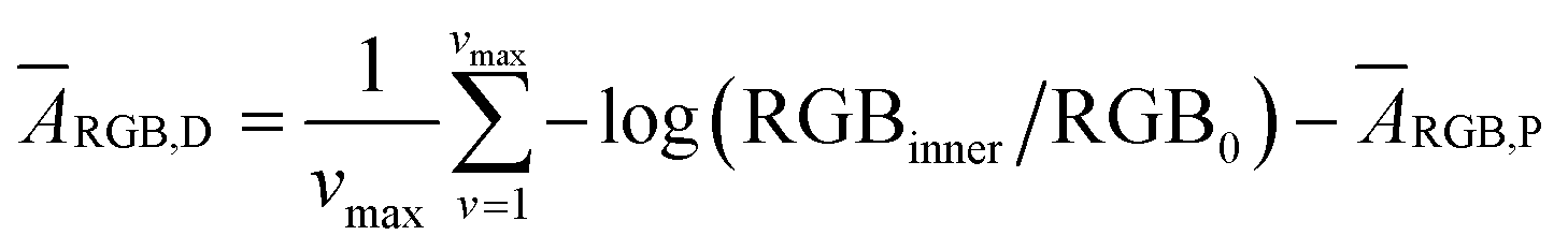 | (9) |
An example of the solution for WD,n in the blue channel using the red channel as a background is represented by eqn (10). The pure dye absorbance on the paper in the blue channel in the kth pixel (ApaperB,k) is then given by the product of the WD,k value solved at each pixel with ĀB,D (eqn (10)).
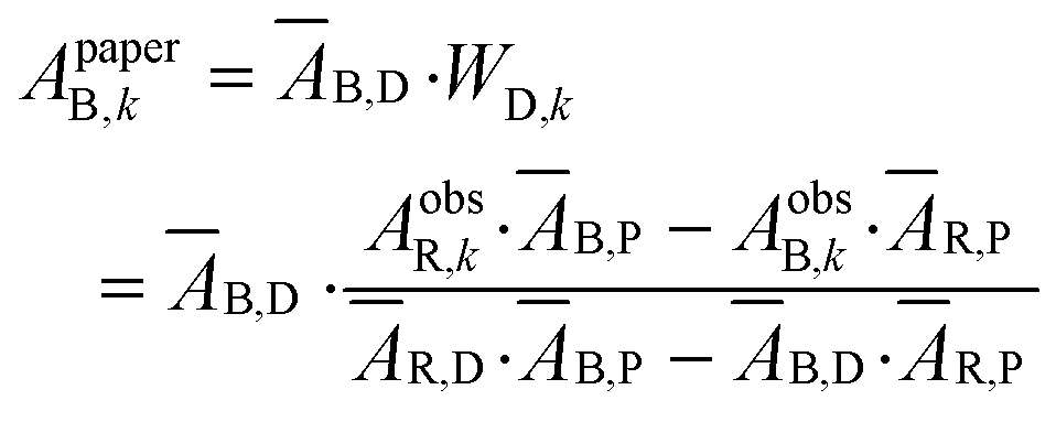 | (10) |
For extremely low dye concentrations or blank paper where there are still thresholded pixels a simplified background subtraction method should be utilized as to avoid calculations based exclusively on noise. The processing software has a simple check implemented to compare the standard deviation of absorbance values between the original image and the signal isolated from paper. If the deviation of the extracted paper background exceeds that of the original image, this is an indication that the dye signal is insufficient for accurate pixel by pixel background calculation. In this event the program switches to a less sophisticated noise reduction technique based on a filtered background channel. See “Background Calculation and Subtraction using Simultaneous Equations” for the relevant code.
Consequently, in Fig. 1c the paper structure is suppressed compared to the uncorrected Fig. 1b. The noise cancelling effect can be best visualized by 3D plots (Fig. 1d and e) where absorbance fluctuations are alleviated after noise cancelling.
The Mathematica computation shown here suggests that the non-invasive measurement of colorimetric absorbance on paper is feasible, in contrast to conventional methods that suffer from paper scattering and require special lab-scaled instruments or additional chemicals to allow incident light to pass through the paper substrate.16–18,21
More importantly, this computation algorithm is applicable to neutral red (NR) to which all the three channels substantially respond (see Fig. S3d and e†) due to its broad absorbance on the paper substrate while ThT has a nearly response-free channel (see Fig. S3a–c†). To implement the quantification for NR, the same spot test was conducted with NR (see Fig. S5†) to obtain eqn (S2)† which can convert absorbance information to quantity of NR. Absorbance mapping before and after noise extraction and 3D mapping of those absorbance and quantity values after conversion by eqn (S2)† are shown in Fig. S6† in analogy to Fig. 1. Thus, from Fig. 1 and S5,† this algorithm is considered to be robust to absorbance spectrum width, which will be further supported by the practical quantification in the next section.
Results and discussion
Quantification of freely dropped dye on paper by flatbed scanner
Based on the absorbance data obtained in the last section (Fig. 1c or e) and eqn (S1),† the quantity of ThT and NR on paper substrate can be calculated. Fig. 1f and S5f† show the resulting quantity profile. Application of eqn (5) to the data in Fig. 1f and S5f† give the total quantity nTDye on the paper substrate.Fig. 2 then shows the quantification of image data for a range of ThT and NR quantities deposited on paper. Absorbance mapping in Fig. 2a and b (see Fig. S7 a and b† for the original ThT and NR data) was done as described above. The high correlation between the calculated and known quantity of those dyes indicates the quantification approach introduced here is neither affected by the heterogeneity of dye on the paper substrate nor the shape of the color spot, given that the pixel density is sufficiently high (600 dpi in this case), in other words, there are a sufficient number of pixels to properly resolve the shape of the spot. Inconsistent color distribution on paper, often observed on paper-based analytical devices as a coffee ring effect, may no longer be problematic for accurate quantification. Indeed, the figures made by low concentration of NR (100, 200, 300 mg L−1) shows color distribution from coffee ring effect where the fringe of the colored area has stronger reddish color (see Fig. S7b†).
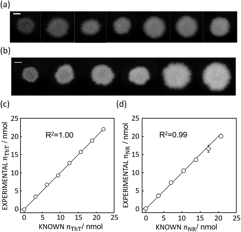 | ||
| Fig. 2 (a) Absorbance mapping of paper substrate stained by 10 μL of ThT without any hydrophobic barrier at, from left to right, 100 to 700 mg L−1, shown with 5 mm scale bar as in Fig. 1. (b) Absorbance mapping of paper substrate stained by 10 μL of NR without any hydrophobic barrier at, from left to right, 100 to 600 mg L−1, shown with 5 mm scale bar. (c) Comparison of calculated and expected amount of ThT on the paper substrate, shown with a line of slope 1 (black line) which represents ideal expected amount of ThT. R2 value obtained by least square fit with the line of slope 1 is 1.00. Error bars are representative of SD n = 3 (d) comparison of calculated and expected amount of NR on the paper substrate, shown with a line of slope 1 (black line) and 0.99 R2 value obtained in the same fashion. | ||
If appropriate, this technique should allow one to accurately quantify image data with completely different color shapes. Here, cross, circle and rod shapes with different dye loadings were chosen for this test as shown in Fig. 3.
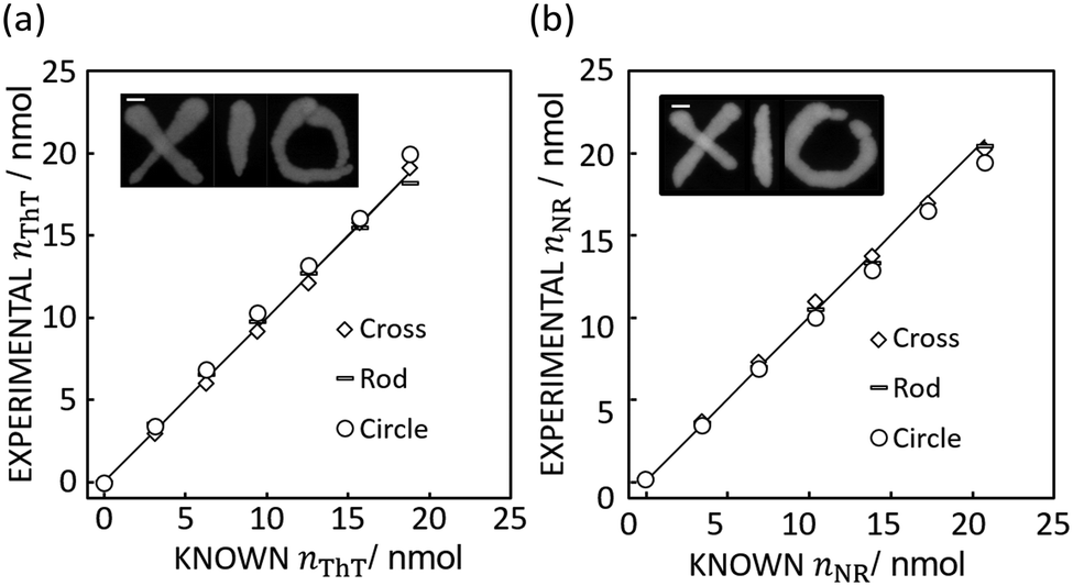 | ||
| Fig. 3 (a) Image inset: Absorbance mapping image of differently shaped ThT color spots on paper prepared by 10 μL of 600 mg L−1 ThT solution with 5 mm error bar. The figure shows the comparison of expected and calculated amounts of dye. R2 values obtained by the least squares method with the line of slope 1 (black line) is 0.99 for cross, 0.99 for rod, and 0.98 for circle respectively. Scale bar is 5 mm as in Fig. 1. (b) Image inset: Absorbance mapping image of differently shaped NR color spots on paper prepared by 10 μL of 600 mg L−1 NR solution with 5 mm scale bar. The figure shows the comparison of expected and calculated amounts of dye. R2 values obtained by the least squares method with the line of slope 1 (black line) is 1.00 for cross, 1.00 for rod, and 0.98 for circle respectively. Scale bar is 5 mm as in Fig. 1. | ||
Indeed, Fig. 3 shows that the method introduced here may appropriately determine the quantity of ThT and NR in color spots of different size and shape, giving a an average relative standard deviation from the known value of 3.06% (cross), 4.24% (rod), and 6.85% (circle) for ThT and 3.78% (cross), 2.56% (rod), 3.71% (circle) for NR.
Application of quantification algorithm to potassium ion sensing
As an example for the application of this technique to real chemical sensing, a capillary-based K+-selective sensor introduced before for K+-selective point-of-care testing2 is used in conjunction with a bare paper substrate. This assay involves a thin K+-selective membrane solvent cast on the inner wall of capillary. The membrane is composed of valinomycin as K+-selective ionophore, NaTFPB as cation exchanger and ThT as indicator dye. Once the sample solution containing K+ is aspirated in the capillary, K+ is selectively extracted into the thin membrane and is replaced by ThT. ThT is accordingly extracted out into the aqueous sample phase which is in turn discharged on the bare paper. This ion exchange mechanism can be theorized by considering the mass and charge balance of these sensing species as eqn (11) shown below.2 | (11) |
 is the initial concentration of K+ in the sample solution, Vaq and Vorg are the volume of aqueous sample solution and membrane organic phase, RThT+ is the degree of ion exchange, Kex is equilibrium constant of this ion exchange system and ThTT+, LT, and RT are the concentration of ThT, ionophore (valinomycin) and cation exchanger (NaTFPB) in organic phase before ion exchange.
Fig. 4a shows the actual images after 10 μL of aqueous sample solutions containing ThT were dropped onto the paper substrate (see Fig. S8† for the original figures).
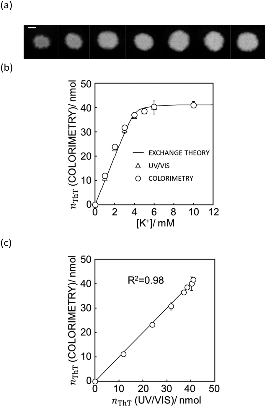 | ||
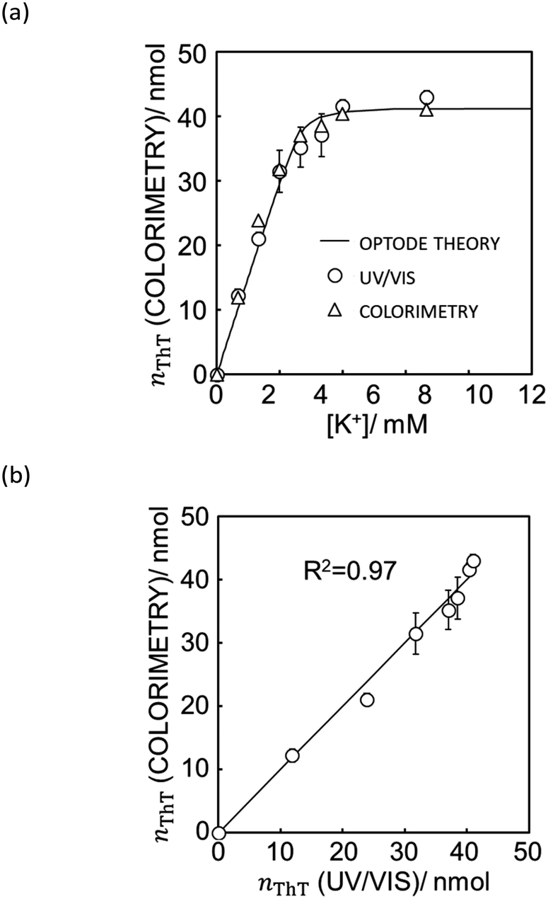
| Fig. 4 (a) The actual image of paper substrate colored by the K+ sample solution after ion exchange shown with 5 mm scale bar as in Fig. 1. (b) Ion exchange response characterized by UV/vis spectrophotometer (white triangles) and quantification of ThT on the image data by Mathematica computing software (white circles) and the theoretical ion exchange behavior described by eqn (11) (black line). (c) The correlation of exchanged ThT amount acquired from UV/vis spectrometer and image analysis by means of Mathematica computation. R2 value obtained by least square fit with the line of slope 1 is 0.98 as shown in (c). | ||
As shown in Fig. 4b, the paper substrate on which sample solutions were freely discharged can be characterized by the colorimetric method introduced here, and the optode behavior obtained by image analysis correlates with the theoretical behavior described by eqn (11). Moreover, as shown in Fig. 4c, each value correlates well to the one calculated from UV/vis spectrophotometry. This suggests that a hydrophobic barrier on paper is no longer strictly necessary for quantitation, which may greatly reduce the complexity of paper-based devices.
Quantitation of dye on the paper substrate by smartphone
Besides flatbed scanners, smartphones are among the most attractive tools for data acquisition from the standpoint of point-of-care and field-based testing, and especially so in combination with paper-based analytical devices. Since each smartphone has a proprietary gamma correction, the value should be obtained to correctly quantify a colorimetric signal on paper. Gamma correction value can be calculated by eqn (1) if the theoretical colorimetric and actual colorimetric values are given. ThT-colored paper spots confined by a hydrophobic barrier was used for the acquisition of gamma values. Theoretical colorimetric absorbance values of each paper spot were calculated based on the previously reported spectral sensitivity of iPhone XR and the result of reflectance measurement22 on the paper spot. Colorimetric absorbance values were obtained by taking a picture of the paper spots in a hand-made shooting studio. The mean of gamma correction values calculated by eqn (1) was used as gamma correction value, determined here as 1/1.26. This relatively high gamma correction value is understandable considering the strong light from LEDs equipped in the hand-made studio. Most of camera devices apply high gamma correction to lessen the output brightness, in other words, higher gamma correction value can make the output picture darker.In addition to gamma correction, the difference of spectral sensitivity between iPhone and Canoscan 9000f Mark II should be taken into account. This can be done by calculating the theoretical colorimetric absorbance value based on the reflectance values for each imaging device as reported earlier22 and just above. The total colorimetric absorbance from the scanner is 1.91 times larger than that of the smartphone on average. In conclusion, the colorimetric absorbance value of the iPhone should be corrected by eqn (12).
 | (12) |
With eqn (12) and Mathematica computation, as seen in Fig. 5a, a smartphone is sufficiently useful to quantify the ionic dye exchange from the capillary-based K+-selective sensor. Comparison of the response with UV/VIS spectrometry (see Fig. 5b) gives good correlation although the accuracy is slightly less than with the scanner (see Fig. 4). This is understandable considering the much higher resolution and controlled lighting and recording conditions of scanner-based images than with smartphones.
 | ||
| Fig. 5 (a) Ion exchange response characterized by UV/vis spectrophotometer (white triangle), quantification of ThT on the image data taken by iPhone XR (white circle) and the theoretical ion exchange behavior described by eqn (11) (black line). (b) The correlation of exchanged ThT amount acquired from UV/vis spectrometer and image analysis by means of Mathematica computation. R2 value obtained by least square fit with the line of slope 1 is 0.97 as shown in (b). See Fig. S9† for the original image data taken by iPhone XR. | ||
Conclusions
Quantification of dye can be done at the single pixel level by computation with Mathematica or other appropriate computing software. This approach allows one to quantify the dye on a paper substrate even if the dye is not homogeneously distributed. For this to work, the relationship between colorimetric absorbance and dye loading, which may deviate from Beer's law, must be known.Upon elimination of gamma correction, most imaging devices may in principle be explored for quantification. In this work, a Canosan 9000f Mark II flatbed scanner was used because gamma correction can be controlled and disabled. The iPhone XR smartphone camera was used as second example in which gamma correction was experimentally determined and eliminated.
The program developed here can extract the pristine dye absorbance from paper noise and deflection, and seems to is robust enough to handle dyes of widely varying spectral characteristics.
Images of paper substrates used for the capillary sensor experiment taken by the two imaging devices were successfully used to quantify ion-selective sensing behavior, even though the paper substrate was stained arbitrarily without hydrophobic barriers or channels. This work should help elevate colorimetric analysis to a more robust, quantitative readout principle for the realization of truly useful paper-based analytical devices.
Contributions
Conceptualization, Y. S. and E. B.; methodology, Y. S. and E. B. investigation, Y. S.; software, Y. S. and K. J. R.; writing – original draft, Y. S.; writing – review & editing, Y. S., K. J. R. and E. B.; funding acquisition, E. B.; resources, T. J. C. and E. B.; supervision, E. B.Conflicts of interest
There are no conflicts to declare.Acknowledgements
This work was supported by the Swiss National Science Foundation and by the Swiss State Secretariat for Education, Research and Innovation (SERI) through a Swiss Government Excellence Scholarship (to K. J. R.).Notes and references
- A. W. Martinez, S. T. Phillips, M. J. Butte and G. M. Whitesides, Angew. Chem., Int. Ed., 2007, 46, 1318–1320 CrossRef CAS.
- Y. Soda, D. Citterio and E. Bakker, ACS Sens., 2019, 4, 670–677 CrossRef CAS PubMed.
- Y. Soda, H. Shibata, K. Yamada, K. Suzuki and D. Citterio, ACS Appl. Nano Mater., 2018, 1, 1792–1800 CrossRef CAS.
- C. T. Gerold, E. Bakker and C. S. Henry, Anal. Chem., 2018, 90, 4894–4900 CrossRef CAS PubMed.
- H. Shibata, T. G. Henares, K. Yamada, K. Suzuki and D. Citterio, Analyst, 2018, 143, 678–686 RSC.
- H. Shibata, Y. Hiruta and D. Citterio, Analyst, 2019, 144, 1178–1186 RSC.
- L. Ge, J. Yan, X. Song, M. Yan, S. Ge and J. Yu, Biomaterials, 2012, 33, 1024–1031 CrossRef CAS.
- X. Li, J. Tian and W. Shen, Anal. Bioanal. Chem., 2010, 396, 495–501 CrossRef CAS PubMed.
- Q.-M. Feng, J.-B. Pan, H.-R. Zhang, J.-J. Xu and H.-Y. Chen, Chem. Commun., 2014, 50, 10949 RSC.
- K. Yamada, T. G. Henares, K. Suzuki and D. Citterio, ACS Appl. Mater. Interfaces, 2015, 7, 24864–24875 CrossRef CAS PubMed.
- K. Yamada, S. Takaki, N. Komuro, K. Suzuki and D. Citterio, Analyst, 2014, 139, 1637 RSC.
- S. Liu, W. Su and X. Ding, Sensors, 2016, 16, 2086 CrossRef.
- H. Kudo, K. Maejima, Y. Hiruta and D. Citterio, SLAS Technol., 2020, 25, 47–57 Search PubMed.
- I. Banerjee, S. G. Aralaguppe, N. Lapins, W. Zhang, A. Kazemzadeh, A. Sönnerborg, U. Neogi and A. Russom, Lab Chip, 2019, 19, 1657–1664 RSC.
- L. Zheng, G. Cai, S. Wang, M. Liao, Y. Li and J. Lin, Biosens. Bioelectron., 2019, 124–125, 143–149 CrossRef CAS PubMed.
- M. Bond, C. Elguea, J. S. Yan, M. Pawlowski, J. Williams, A. Wahed, M. Oden, T. S. Tkaczyk and R. Richards-Kortum, Lab Chip, 2013, 13, 2381 RSC.
- J. F. d. S. Petruci, P. C. Hauser and A. A. Cardoso, Sens. Actuators, B, 2018, 268, 392–397 CrossRef CAS.
- D. C. M. Ferreira, G. F. Giordano, C. C. dos Santos Penteado Soares, J. F. A. de Oliveira, R. K. Mendes, M. H. Piazzetta, A. L. Gobbi and M. B. Cardoso, Talanta, 2015, 141, 188–194 CrossRef CAS.
- L. Zong, Y. Han, L. Gao, C. Du, X. Zhang, L. Li, X. Huang, J. Liu, H.-D. Yu and W. Huang, Analyst, 2019, 144, 7157–7161 RSC.
- H. Fu, P. Song, Q. Wu, C. Zhao, P. Pan, X. Li, N. Y. K. Li-Jessen and X. Liu, Microsyst. Nanoeng., 2019, 5, 50 CrossRef.
- A. K. Ellerbee, S. T. Phillips, A. C. Siegel, K. A. Mirica, A. W. Martinez, P. Striehl, N. Jain, M. Prentiss and G. M. Whitesides, Anal. Chem., 2009, 81, 8447–8452 CrossRef CAS.
- Y. Soda and E. Bakker, ACS Sens., 2019, 4, 3093–3101 CrossRef CAS PubMed.
- L. Gao and R. T. Smith, J. Biophotonics, 2015, 8, 441–456 CrossRef.
Footnote |
| † Electronic supplementary information (ESI) available: Fitting function of colorimetric absorbance and quantity of ThT in a pixel, example of elimination of colored pixel and calculation of background RGB value; image sample split into R, G and G channel; example of noise extraction from red channel in a one dimensional way; original figures used in this work; Mathematica code used in this work. See DOI: 10.1039/d0lc00028k |
| This journal is © The Royal Society of Chemistry 2020 |