
 Open Access Article
 This Open Access Article is licensed under a
 Creative Commons Attribution 3.0 Unported Licence
Integrating microfluidics and biosensing on a single flexible acoustic device using hybrid modes†
Ran
Tao
 ab,
Julien
Reboud
c,
Hamdi
Torun
b,
Glen
McHale
b,
Linzi E.
Dodd
b,
Qiang
Wu
b,
Kai
Tao
d,
Xin
Yang
e,
Jing Ting
Luo
*a,
Stephen
Todryk
f and
Yongqing
Fu
*b
ab,
Julien
Reboud
c,
Hamdi
Torun
b,
Glen
McHale
b,
Linzi E.
Dodd
b,
Qiang
Wu
b,
Kai
Tao
d,
Xin
Yang
e,
Jing Ting
Luo
*a,
Stephen
Todryk
f and
Yongqing
Fu
*b
aShenzhen Key Laboratory of Advanced Thin Films and Applications, College of Physics and Energy, Shenzhen University, 518060, Shenzhen, China. E-mail: luojt@szu.edu.cn
bFaculty of Engineering and Environment, Northumbria University, Newcastle upon Tyne, NE1 8ST, UK. E-mail: richard.fu@northumbria.ac.uk
cDivision of Biomedical Engineering, James Watt School of Engineering, University of Glasgow, Glasgow, G12 8LT, UK
dMinistry of Education Key Laboratory of Micro and Nano Systems for Aerospace, Northwestern Polytechnical University, Xi'an, 710072, PR China
eDepartment of Electrical and Electronic Engineering, School of Engineering, Cardiff University, CF24 3AA UK
fFaculty of Health and Life Sciences, Northumbria University, Newcastle upon Tyne, NE1 8ST, UK
First published on 3rd February 2020
Abstract
Integration of microfluidics and biosensing functionalities on a single device holds promise in continuous health monitoring and disease diagnosis for point-of-care applications. However, the required functions of fluid handling and biomolecular sensing usually arise from different actuation mechanisms. In this work, we demonstrate that a single acoustofluidic device, based on a flexible thin film platform, is able to generate hybrid wave modes, which can be used for fluidic actuation (Lamb waves) and biosensing (thickness shear waves). On this integrated platform, we show multiple and sequential functions of mixing, transport and disposal of liquid volumes using Lamb waves, whilst the thickness bulk shear waves allow us to sense the chemotherapeutic Imatinib, using an aptamer-based strategy, as would be required for therapy monitoring. Upon binding, the conformation of the aptamer results in a change in coupled mass, which has been detected. This platform architecture has the potential to generate a wide range of simple sample-to-answer biosensing acoustofluidic devices.
1 Introduction
Rapid developments in microfluidics and biosensing technologies could allow healthcare providers to focus on continuous patient monitoring and disease diagnosis using mobile and point-of-care technologies.1 A range of lab-on-a-chip (LOC) diagnostic platforms have been developed following the advances in micro- and nanotechnology, to deliver biochemical assays using minimal sample consumption, while enabling rapid analysis, and reduced cost. However, few LOC tests have been successfully introduced into the market, due to the complexity in device architecture linked to the need for liquid handling (for sample and reagents movement and purification, i.e. washing) as well as sensitive molecular sensing. In general, these two different functionalities are addressed using different platforms, such as capillary or hydrodynamic flow for liquid pumping and optics, and impedance or electrochemistry for biosensing, for example.1,2In this context, digital microfluidic systems have allowed the use of mature fabrication processes through photolithography techniques3 and the elimination of the need for external modules or complicated geometries such as pumps or valves.4,5 Amongst several actuation mechanisms for digital microfluidics, such as electrowetting-on-dielectrics (EWOD),6 dielectrophoresis (DEP),7 opto-electrowetting,8 thermocapillary,9 magnetic actuation,10 microfluidic devices based on surface acoustic waves (SAWs)/Lamb waves have proven advantageous as they are able to provide a host of useful effects, including acoustic streaming in droplets, efficient mixing, transportation and jetting, and acceleration of hybridization reactions of biochemical assays.11,12
More generally, acoustic wave devices are uniquely attractive to generate fully integrated LOC systems, as they can also enable biosensing in addition to liquid actuation, wirelessly,13–15 thus significantly reducing complexity of the system and operation/manufacturing costs. Acoustic biosensing devices include quartz-crystal microbalances (QCM),16 SAWs,17 and film bulk acoustic resonators (FBAR).18 These sensors can detect traces of biomolecules through their binding to biomarkers immobilized onto their surfaces.19 Shear horizontal SAWs (SH-SAWs) and thickness shear mode (TSM) acoustic waves are often generated on structures of c-axis inclined piezoelectric thin-films on SAW and FBAR devices,18,20 significantly increasing the quality factor of the resonator in liquid phase, suitable for sensing of antibody, drug and blood samples. Precision sensing using either SAWs or FBARs or microfluidic functions using SAWs have been reported on ZnO thin film-based acoustic platform.12,21–23 In addition to their inherent advantages of low toxicity, biocompatibility and biodegradability,3,21,24 ZnO films can be easily deposited onto flexible or bendable substrates, thus opening up the potential for wearable acoustic wave devices.3,25
The current solution to integrate both sensing and liquid actuation onto a thin film acoustic platform relies on inclined angled film designs, which are able to generate both shear waves and longitudinal or Rayleigh SAW waves on a single device.3 However, it is difficult to realise uniform films with constant values of inclined angles and consistent acoustic wave properties over large areas, as would be required for microfluidic processing (where samples are often a few microlitres in volume).3
In this study, we propose a new and simple concept integrating both Lamb waves and TSMs on a flexible ZnO/Al acoustic device with potential applications for flexible, bendable and wearable LOC systems. Instead of using shear modes of FBARs, which are difficult to fabricate and control, we use lateral field excitation of thickness shear mode (LFE-TSM) for biosensing. In this hybrid acoustic wave platform, we show that both the Lamb wave mode and LFE-TSM mode can be excited individually at their resonant frequencies, thus enabling to perform sampling, patterning and biosensing selectively in a single device. We illustrate this functionality through the detection of an anticancer drug Imatinib, a specific tyrosine kinase receptor inhibitor. Its concentration in blood is correlated with the clinical response of cancer patients.26 We used an aptamer as a capture molecule functionalised on the surface of our device. As the binding occurs, the complex loses mass, resulting a detectable resonant frequency shift.
2 Lab-on-a-chip design using hybrid modes
The device design is based on conventional SAW interdigital transducers (IDTs) on a bendable or flexible thin plate (in which the wavelength of the IDTs is generally larger than the plate thickness). As illustrated in Fig. 1a, the fundamental antisymmetric Lamb wave (A0) and symmetrical Lamb wave (S0) are generated using the IDTs. A0 and S0 waves induce small-amplitude acoustic streaming inside droplets placed on the path of the propagating waves.3 These modes can be effectively used to dilute and mix liquid samples. As the excitation amplitude increases, the acoustic pressure can be increased beyond a threshold value when the droplet can be moved forward, as illustrated in the schemes in Fig. 1.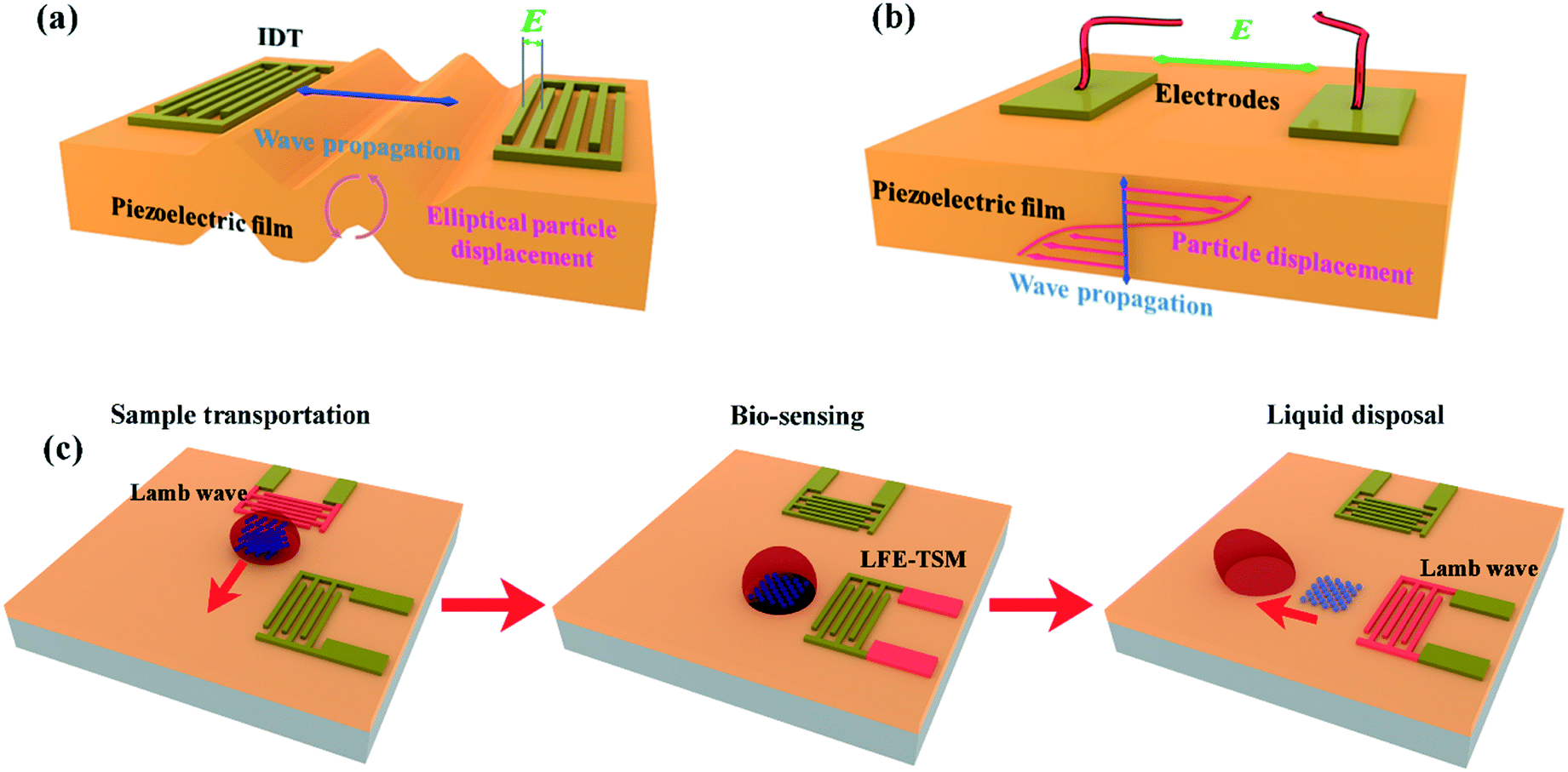 | ||
| Fig. 1 Illustrations of the generation of (a) Lamb wave for liquid actuation and (b) LFE-TSM for sensing using different parts of a single IDT design. (c) Schemes showing LOC capabilities based on LFE-TSM/Lamb wave hybrid acoustic devices for biosensing and liquid and particle manipulation. | ||
In addition to A0 and S0 waves generated from the IDTs, an LFE-TSM wave (a typical shear bulk acoustic wave) can also be generated using two electrodes deposited on top of a piezoelectric substrate or thin film.27,28 The wave propagates in the plate along the normal to the top surface, with particle motion along shear horizontal direction as shown in Fig. 1b. Higher orders of LFE-TSM waves have been exploited for bio-sensing in liquid since the mechanical energy of these waves is mostly confined in the substrate, so they do not dissipate significantly into liquid.3 We designed our integrated LOC diagnostic platform with enlarged contact pads on the IDTs as shown in Fig. 1c, to enhance the generation of LFE-TSM waves. Our new LOC design allows us to generate each mode on demand by selecting the resonant frequencies of the corresponding wave mode. In this way, we can control different biomedical functions such as sample preparation, bio-sensing and sample patterning more effectively by triggering the most efficient wave mode.
One such implementation is illustrated in Fig. 1c, showing that liquid droplets can be agitated for mixing at the biosampling preparation areas, and then transported to the reaction area, using the Lamb (A0) wave. In the reaction area, the target biomolecule of interest in the droplet sample can be acoustically agitated to facilitate binding to the pre-immobilized capture molecules on the reaction surface using the Lamb wave modes. After binding, the liquid medium or sample waste is pumped away using the Lamb wave mode. The biomarker changes the mass on the surface, which can be measured by monitoring the shift in the resonant frequency of the LFE-TSM. Other functions such as cell alignment and patterning within the large droplet can also be realised using both the Lamb wave and LFE-TSM waves, as will be discussed in the later sections.
3 Experiment and simulation details
3.1 Device fabrication
The hybrid acoustic devices were fabricated by depositing piezoelectric ZnO thin films onto Al plates (with different thicknesses from 50 μm to 1500 μm) using a DC magnetron sputter. A DC power of 400 W was used for the zinc target (99.99% purity) with an Ar/O2 gas flow rate of 10/15 sccm and a pressure level of 4 × 10⁻⁴ mbar. The sample holders were rotated during deposition to obtain uniform ZnO thin films. The film thickness was controlled to be ∼5 μm. The piezoelectric properties of ZnO thin films fabricated using such a method are listed in Table SI1.† The IDTs were fabricated using a conventional photolithographic lift-off process.29 S1813 photoresist was spin-coated onto the ZnO device at a speed of 4000 rpm, baked for 5 min at 110 °C and then exposed to UV light for 7 s with an intensity of 75 mJ cm−2 using a mask aligner (EVG620). The developing time was controlled to be ∼1 min. Cr/Au layers with the thickness of 20 nm/100 nm were deposited using a thermal evaporator (EDWARDS AUTO306) and the electrodes were obtained using a standard lift-off method. The IDTs comprised 50 pairs of electrodes with different wavelengths ranging from 100 μm to 400 μm (Fig. SI1†).The hybrid devices were characterized using a network analyser (Keysight N9913A) by measuring their reflection spectra. The displacement profile of different wave modes in the direction normal to the top surface were measured using a laser vibrometer (UHF-120, Polytec GmbH). A signal generator and a power amplifier were used to acoustically excite the hybrid acoustic devices while the droplet movements were recorded using a digital camera.
3.2 Biosensing
The sensing areas of the devices were treated using oxygen plasma with a power of 100 W for 40 s to activate the -OH groups on the surface. Then, the devices were immersed into (3-aminopropyl)triethoxysilane (APTES) solution for 1.5 hr (1% APTES + 2% distilled water + 97% IPA), and subsequently cleaned using ethanol for 5 min and distilled water for 5 min. The devices were immersed into a 1% (w/v) glutaraldehyde solution for 30 min and rinsed twice. The top surface was treated by immersion in a 0.02 mg mL−1 streptavidin solution for 1 hour at 37 °C and washed 3 times with phosphate-buffered saline (PBS). Prior to the sensing process, the devices were incubated with 1 μM Ima-C5 Displacement Aptamer solution, which includes a biotin moiety (developed and supplied by Aptamer Group Ltd, York, UK) for 30 min. In the final step, the surfaces of the devices were exposed to an Imatinib solution with different concentrations for 30 min. The frequency responses of LFE-TSM waves were recorded at each step using the network analyzer.3.3 Simulations
To understand surface vibration modes under different frequencies of acoustic waves, finite element analysis using the commercial COMSOL software with solid mechanics, electrostatics and pressure acoustics modules was performed. The model was composed of an Al substrate, a ZnO piezoelectric layer, an external water layer and a perfectly matched layer from bottom to top with thicknesses of 200 μm, 5 μm, 600 μm and 300 μm, respectively (see Fig. SI2a†). The cross-section of the model was a 300 μm × 300 μm square. Considering the thickness of the electrode is negligible, a pair of 2D gold electrode fingers with a width of 75 μm and a length of 300 μm were built on top of the ZnO layer, used as the electric ground and floating electric potential (10 V) nodes. Free tetrahedral meshes were built for Al, ZnO, and water layers with the maximum mesh size confined below 2.5 μm, while swept meshes were built for the perfectly matched layer as shown in Fig. SI2b.† The mesh size is a compromise between calculation accuracy and computational costs. In the simulation, periodic conditions were applied to lateral walls of the model marked in Fig. SI2a† to simulate the multiple pairs of IDTs of the real device. The material parameters of Al, ZnO, gold and water used in the simulations are listed in Table SI2.†Wave modes, vibration patterns, relative surface displacements and the harmonic resonant TSM frequencies were calculated using the eigenfrequency analysis in COMSOL. The acoustic pressure fields were simulated in the frequency domain analysis using the corresponding frequency values obtained from the eigenfrequency analysis.
4 Results and discussion
4.1 Hybrid wave mode analysis
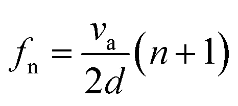
Fig. 2a shows examples of a S11 spectrum of a hybrid device with 300 μm-thick ZnO film deposited onto a 200 μm-thick Al plate. The hybrid device exhibited multiple resonance frequencies. Fig. 2a also shows the S11 spectra of the device with only Lamb waves (e.g., without TSM mode), and a pure TSM mode (generated using only the dual pad electrode patterns) demonstrating that the hybrid-mode devices exhibited the combination of both wave modes. Enlarging the dimensions of electrode pads generally enhances the amplitude of the generated LFE-TSM waves. Hybrid modes have been identified on all the different Al substrates with various Al sheet thicknesses based on our electrode designs (Fig. 2b). The presence of both Lamb waves and LFE-TSM waves on 200 μm-thick Al was verified using both the simulation and experimental results. For the devices on 600 μm- and 1.5 mm-thick Al, the standard Rayleigh wave modes and Sezawa modes could be obtained along with the LFE-TSM waves (as shown in Fig. 2b). | ||
| Fig. 2 (a) Reflection S11 spectra of hybrid TSM/SAW devices with a designed wavelength of 300 μm (black), compared to LFE-TSM and Lamb wave devices fabricated separately (red and green respectively). (b) Reflection S11 spectra of hybrid TSM/SAW devices based on Al sheets with the thicknesses of 200 μm (black), 600 μm (blue) and 1.5 mm (red). The designed wavelength is 100 μm. (c) S-TSM resonant frequencies increase linearly as the frequency increases with fixed interval corresponding to the device thickness. The inset shows that frequency interval is proportional to the reciprocal of device thickness. (d) Reflection S11 spectra of hybrid acoustic devices on 200 μm thick Al plates with the designed wavelengths of the IDTs varying from 100 μm to 400 μm. | ||
The frequency of TSM waves can be calculated using eqn (1):
 | (1) |
We also demonstrated that the two wave mode types can be controlled independently through the design of the device. For example, for an Al substrate with a thickness of 200 μm, different IDT designs with different wavelengths generated different SAWs, while the frequencies of TSM waves, controlled by the thickness, remained the same (Fig. 2d). Similarly, the distance between the two pads, their dimensions or their locations could all be changed whilst the frequencies for the LFE-TSM waves stayed the same (only amplitudes changed).
These experimental results were compared with those from the finite element analysis (FEA) using COMSOL software. Fig. 3 shows that all the resonant peaks correspond to the different modes of both Lamb waves and LFE-TSM waves. For the Lamb waves, both the asymmetrical modes of A0 and A1 and symmetrical modes of S0 and S1 can be observed from the hybrid device. Similarly, the LFE-TSM waves can also be separated into symmetric and anti-symmetric TSM (e.g., A-TSM and S-TSM). Fig. 3b shows the A-TSM and S-TSM resonant frequencies for the hybrid device obtained from both simulation and experiments. The deviations between the FEA and experimental results are ca. 3% for A-TSM and 5% for S-TSM, which are within the expected uncertainty of assumed material properties and geometrical parameters used in the simulations. The FEA model was a unit cell taken from the repeated pairs of IDTs of the real device with periodic boundary conditions (see section 3.3), as previously established for both SAW and Lamb waves.29,30 As with the LFE-TSM waves, a model integrating the actual dimensions of the electrode pads is challenging to build, due to the large aspect ratio between the pad dimensions and the thickness of ZnO thin film. Consequently, we used the same model as for the Lamb waves, with an increased geometry to 600 μm × 600 μm for the fundamental order of the A-TSM. The results presented in Fig. SI3† validate that the effect of the size of the domain on the A-TSM frequencies is negligible (less than 0.001% per 100 μm).
 | ||
| Fig. 3 (a) Wave mode vibration patterns of fundamental anti-symmetric and symmetric LFE-TSM, and A0 and S0 Lamb waves obtained by FEA. (b) Comparison of resonant frequencies of both A-TSM and S-TSM from experimental and FEA results. (c) Displacements of the top surface along its normal direction agitated by A0 and S-TSM waves. Results were acquired from laser vibrometer measurements and FEA simulation. | ||
We then validated the out-of-plane displacements of the waves using laser vibrometry (see Fig. 3c), and the results show that the displacement on the surface exhibits a sine-pattern with a wavelength of 300 μm for the A0 Lamb wave, consistent with our simulation results. This vertical component of the waves interacts strongly with the liquid placed on the solid substrate, hence transferring the mechanical energy and providing the ability of droplet manipulation.
Although, in principle, the mechanical vibrations of the LFE-TSM (the second order of S-TSM) should be confined within the ZnO/Al layer, both the experimental and simulation results reveal vertical or normal displacements that are periodic along the horizontal plane. We believe that the LFE-TSM generates minor vertical vibrations since the thickness of the Al sheet device is much smaller compared than a conventional bulk substrate. Nevertheless, the amplitude of LFE-TSM (typically <5 pm peak-to-peak) at a given excitation power is significantly smaller as compared to that of Lamb waves (typically >20 pm peak-to-peak) and would not constitute an efficient solution for droplet transport. This will be further discussed in the following sections.
4.2 Microfluidic functions from hybrid modes
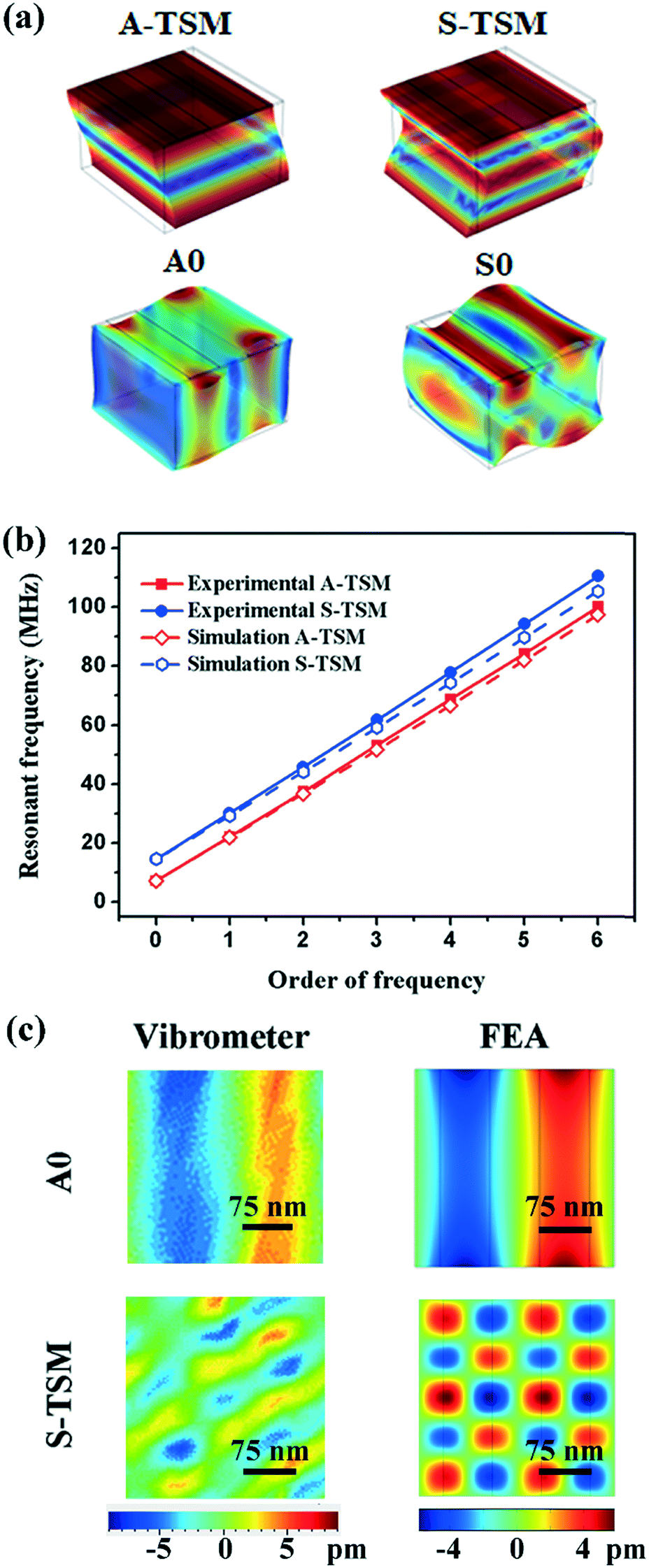
For the biosampling and acoustofluidic functions, we used the A0 wave generated using the hybrid device with a wavelength of 300 μm on a 200 μm-thick Al substrate because the Lamb wave generates significant acoustic streaming and acoustic radiation force on liquid droplets. In the following experiments, microliter scale of droplets, e.g., 1 μL, were used as it is in the general volume range of sampling before further dilution for biosensing applications. Fig. 4a presents a mixing process agitated by the A0 wave with the corresponding frequency of 8.6 MHz. In this case, a 2 μL droplet sample was added to a distilled water droplet (2 μL) to simulate dilution or reagent addition. Without any external stimulation, the polystyrene particles tended to accumulate in the top region of the mixed droplet. When the A0 Lamb wave was applied to the system, it generated acoustic streaming, thus effectively mixing both components. We analysed the video frames acquired at 30 fps, starting from the first actuation of the drop to the formation of uniform dark blue colour (as measured by a standard deviation <0.04 s), leading to a mixing time 0.25 s. As the input power was increased to 2.8 W, the radiation force of A0 Lamb wave became dominant and drove the sample droplet to move forward (Fig. 4b). Fig. 4c shows the measured transport velocities of 1 μL droplet, increasing significantly with power. The average velocity reached a maximum of 6 mm s−1 at an input power of 6.8 W when the droplet was transported on the top surface of the device (where the IDTs are patterned). | ||
| Fig. 4 (a) 2 μL of a blue polystyrene particles suspension in water (diameter of 2 μm) was mixed with same volume of distilled water using A0 wave with input power of 0.52 W. (b) 1 μL distilled water droplet moving along the surface driven by A0 wave with input power of 2.88 W. (c) Average velocity of droplet transport varying with the input power driven by A0 Lamb wave (8.6 MHz) on both top (red squares) and back surfaces (blue circles). | ||
Droplet transportation can also be easily realized on the back side of the SAW device as the wavelength is much larger than the device thickness, and thus the Lamb wave is dominant. Fig. 4c also presents the measured transportation velocities of droplet at the back side of the SAW device as a function of applied power. The transportation velocity is a function of the input power and can reach 4 mm s−1 at a power of 6.8 W. The different performance between the top and back sides with the same standard A0 Lamb wave could be attributed due to the different surface structures, however these results confirm the ability of both sides to sustain droplet movement. Compared with the results from a pure Lamb wave device, the hybrid mode device has maintained 79% of the efficiency. For example, the pure Lamb wave can enable the droplet transport with an average velocity of 6.5 mm s−1 at a power of 5.8 W. Nevertheless, one advantageous using the hybrid mode for the LOC applications is that both metal IDTs and piezoelectric layer can be protected from the corrosive/contaminated environments due to the presence of bio-samples. Droplet transportation can also be achieved using the LFE-TSM waves due to their small vertical vibration components, which have been identified from the vibrometry (see Fig. 3c) and experimental results (Fig. SI4a–c†). However, the required power to initiate the LFE-TSM-activated transportation was over 10 W due to smaller vertical wave amplitudes, whilst to maintain an acceptable transport velocity, the device required >30 W. Therefore, the Lamb waves is preferred in the applications of biosampling and transportation of droplet samples.
4.3 Acoustic tweezing
We also proved that acoustic pressure nodes can be quickly formed using the A-TSM, S-TSM and A0 Lamb waves, which could be applied to trap microparticles or potentially cell specimens for further investigations. The capability was demonstrated using silicon dioxide particles with a diameter of 5 μm immersed in distilled water. Firstly, we performed the FEA simulations and obtained the vibration patterns generated by both the LFE-TSM and Lamb wave modes. Fig. 5a to d reveal the pressure distributions on top of the hybrid device. We then performed the experiments based on the same conditions. The photograph of silicon dioxide particles prior to any acoustic wave propagation in Fig. 5e exhibits a random distribution.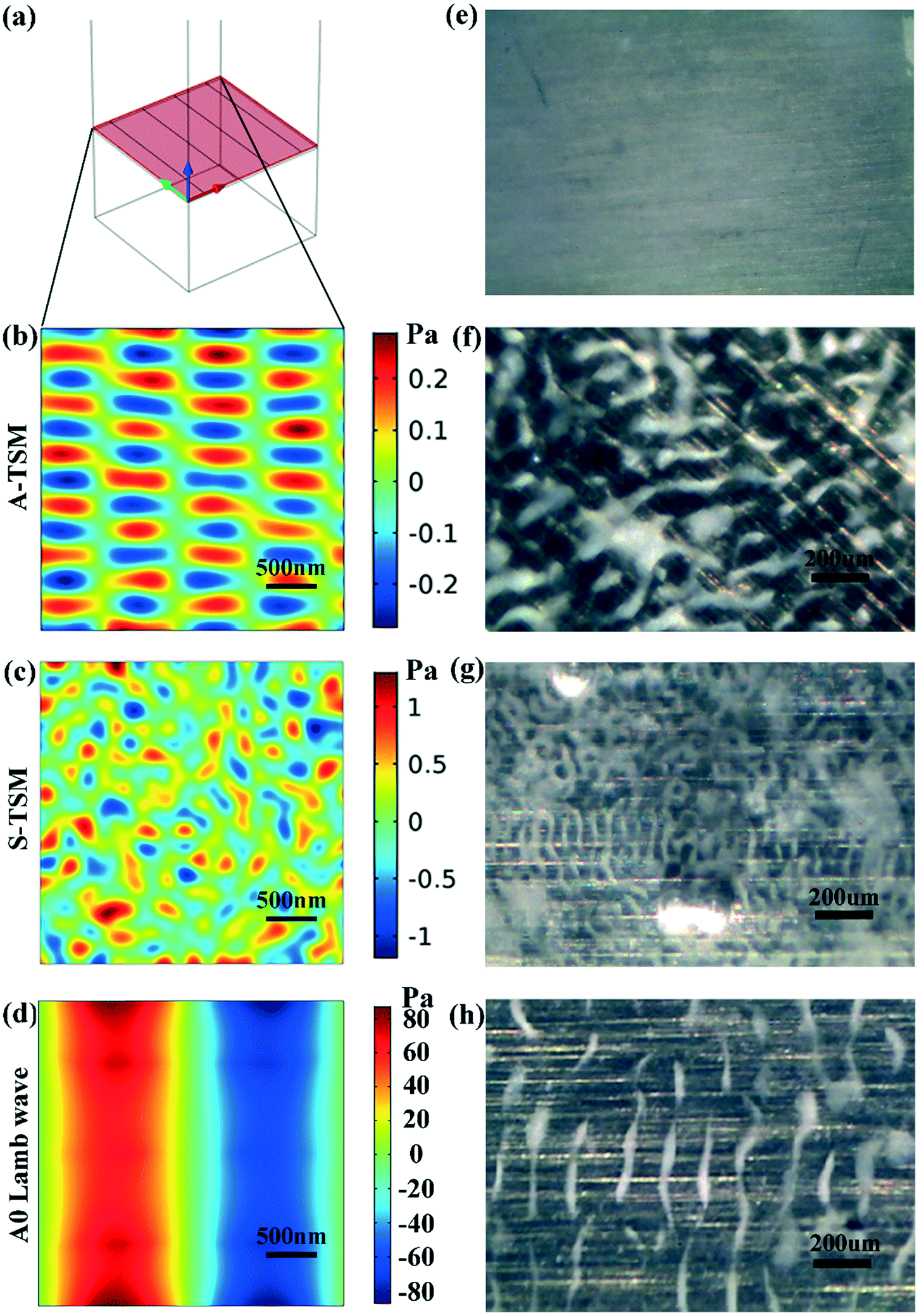 | ||
| Fig. 5 Acoustic pressure field obtained from FEA simulations and 5 μm silicon dioxide particle patterns shown in experiments driven by LFE-TSM and Lamb waves. (a) 3D scheme showing the cross-section (xy-plane, red colour) at the liquid–solid interface. Acoustic pressure field acquired from simulations formed by (b) A-TSM (7.41 MHz, 0.1 W), (c) S-TSM (14.15 MHz, 0.1 W) and (d) A0 Lamb wave (8.6 MHz, 0.1 W). (e) Silicon dioxide particles uniformly mixed prior to acoustic waves. Silicon dioxide particles form different patterns driven by (f) A-TSM, (g) S-TSM and (h) A0 Lamb wave. | ||
Upon excitation with the fundamental A-TSM wave (7.41 MHz), these silicon dioxide particles were aligned quickly along a wavy grid pattern defined by the acoustic pressure field (Fig. 5f). By tuning the excitation frequency to fundamental S-TSM mode (14.15 MHz), we achieved a matrix of dot pattern as presented in Fig. 5g. We also explored the alignment configuration patterned using the A0 Lamb wave (8.6 MHz), where the distance between adjacent patterned lines was equal to half of the wavelength, in this case, about 150 μm (Fig. 5h). The demonstrated particle trapping function could be further explored for 3D patterning by increasing the depth of the liquid/droplet for cell patterning applications,31,32 such as for forming 3D cell networks facilitating neurite growth and guidance, as well as other applications in tissue engineering.
4.4 Demonstration of biosensing applications using hybrid modes
In addition to microfluidic functions, we demonstrated the detection capability of the hybrid device with a case study in biosensing of the anticancer drug Imatinib where the device was functionalised with the Displacement Aptamer ‘Ima-C5Aptamer’ as a capture-release molecule. Fig. 6a shows both the surface chemistry processes (through a conventional streptavidin–biotin coupling of a capture molecule) and the sensing principle (which relies on the release of a component of the Aptamer molecule Ima-C5 upon binding with the target drug Imatinib). The release of the Imatinib-Aptamer complex is accompanied by a decrease in the mass attached on the surface of the hybrid device (by 31.5 kDa).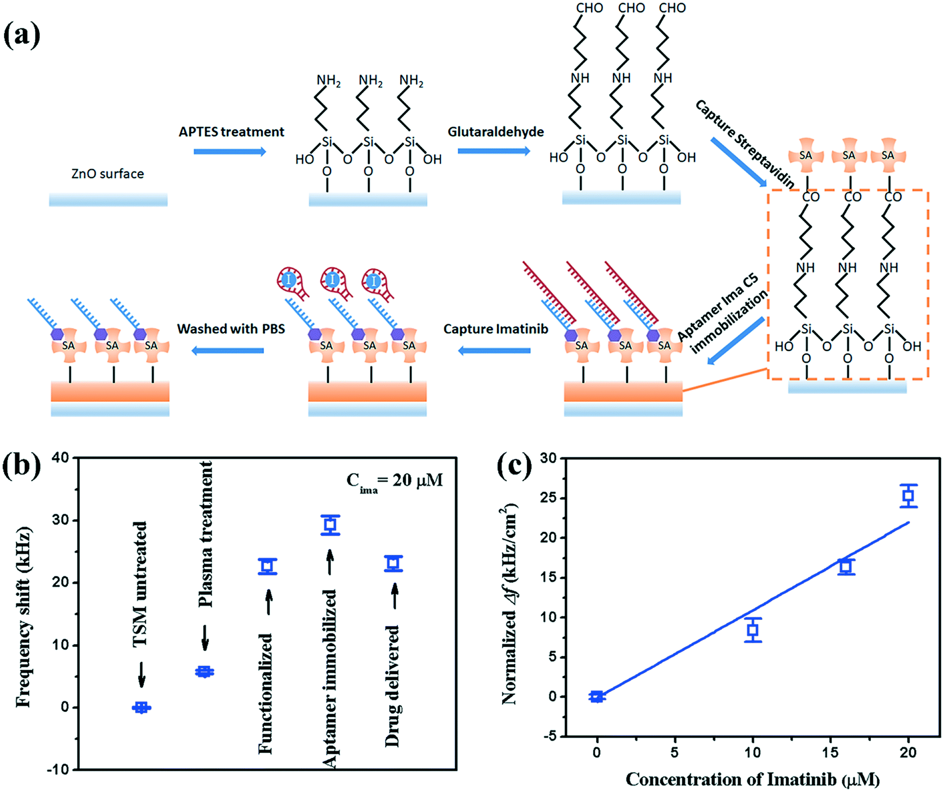 | ||
| Fig. 6 (a) Schemes showing the mechanism of immobilization of Ima C5 Aptamer and the detection of Imatinib drug. (b) Typical frequency shifts (absolute value) corresponding to each step of Imatinib sensing; (c) normalized frequency shift (absolute value) of LFE-TSM waves varying with the concentration of Imatinib. | ||
Fig. 6b shows one of the typical results of frequency shifts of LFE-TSM waves (using 30 MHz – see Fig. 2a for S11 characteristics), corresponding to the functionalisation of the surface, referenced to the surface prior to treatment. As the molecules were attached onto the surface, the resonant frequency was decreased due to mass loading. However, when Imatinib (20 μM) was added, the resonant frequency was increased. This is in agreement with the biochemical process shown in Fig. 6a, provided by the supplier, where part of the complex is released from the surface upon binding with drug molecules. Similar results were obtained for 46 MHz (see Fig. SI5†).
The frequency differences between the last two steps (before and after addition of Imatinib) can be used to measure the Imatinib concentration in solution. Fig. 6c shows the normalised frequency shifts (e.g., the frequency shift divided by the functional area) as a function of Imatinib concentration. As the Imatinib concentration was increased, the normalised frequency shift was increased. The sensitivity can be obtained by a linear fitting of the curve in Fig. 6c, and the result is ∼1.1 kHz cm−2 μM−1 for the resonant frequency of 30 MHz.
Considering that the mass of the ‘Aptamer–Imatinib’ complex as 31.5 kg mol−1 and that the volume of Imatinib solution applied to each device was 20 μL, the sensitivity can also be converted to 0.11 Hz cm2 ng−1. QCM biosensors have been shown to achieve sensitivities varying from 0.057 Hz cm2 ng−1 to 0.54 Hz cm2 ng−1.33,34 However, since the mass sensitivity of bulk acoustic waves sensors (QCM, LFE-TSM, FBAR…) is proportional to the reciprocal of the device thickness,35 much higher sensitivities have been obtained using FBAR sensors (up to ∼103 Hz cm2 ng−1 for example), with thickness of a few-hundred nanometers.34,35 The hybrid strategy presented should be able to reach higher sensitivities by decreasing the thickness of the Al substrate, although maintaining the microfluidic functionalities, both in terms of acoustic wave transmission and mechanical strength of the overall device, will rapidly limit practical implementations.
5 Conclusions
A new platform of integrated thickness shear/Lamb hybrid wave modes based on flexible thin film acoustic waves has been demonstrated in this study to perform both microfluidic actuation of liquids and biosensing on the same device. In this platform, Lamb waves were excited for sample dilution and transport, by adjusting the input SAW power. The LFE-TSM waves enabled particle patterning by agitating fundamental orders with low input power, as well as biosensing by monitoring the frequency shifts for higher order waves. The LFE-TSM waves were found to have a rational sensitivity of 1.1 kHz cm−2 μM−1 for Imatinib drug sensing. We demonstrate that this device could have great potential as a fully integrated, flexible lab-on-a-chip, enabling bio-assays for point-of-care applications.Author contributions
Y. Q. Fu, J. Reboud and R. Tao proposed the idea. R. Tao, S. Todryk and J. Reboud performed the experimental work. R. Tao, J. Reboud and Y. Q. Fu wrote the manuscript and performed analysis. H. Torun, G. McHale, L. E. Dodd, Q. Wu, K. Tao, X. Yang, and J. T. Luo provided critical review and commentary to the article.Conflicts of interest
There are no conflicts to declare.Acknowledgements
This work was financially supported by Research and Development Program of China (Grant no. 2016YFB0402705), the UK Engineering and Physical Sciences Research Council (EPSRC) grants EP/L026899/1, EP/P018998/1 and EP/K027611/1, Shenzhen Key Lab Fund (ZDSYS20170228105421966), Shenzhen Science & Technology Project (Grant no. JCYJ20170817100658231). The work is also supported by Special Interests Group of Acoustofluidics under the EPSRC-funded UK Fluidic Network (EP/N032861/1). Special acknowledgments go to Aptamer Group Ltd (http://www.aptamergroup.co.uk) for providing the aptamer and Imatinib, and advice on their use.References
- S. K. Vashist, P. B. Luppa, L. Y. Yeo, A. Ozcan and J. H. T. Luong, Trends Biotechnol., 2015, 33, 692–705 CrossRef CAS PubMed.
- S. A. N. Gowers, M. L. Rogers, M. A. Booth, C. L. Leong, I. C. Samper, T. Phairatana, S. L. Jewell, C. Pahl, A. J. Strong and M. G. Boutelle, Lab Chip, 2019, 19, 2537–2548 RSC.
- Y. Q. Fu, J. K. Luo, N. T. Nguyen, A. J. Walton, A. J. Flewitt, X. T. Zu, Y. Li, G. McHale, A. Matthews, E. Iborra, H. Du and W. I. Milne, Prog. Mater. Sci., 2017, 89, 31–91 CrossRef CAS.
- S. K. Cho, H. Moon and C. J. Kim, J. Microelectromech. Syst., 2003, 12, 70–80 CrossRef.
- M. G. Pollack, R. B. Fair and A. D. Shenderov, Appl. Phys. Lett., 2000, 77, 1725–1726 CrossRef CAS.
- J. Li, N. S. Ha, T. L. Liu, R. M. van Dam and C.-J. C. J. Kim, Nature, 2019, 572, 507–510 CrossRef CAS PubMed.
- S. K. Fan, H. P. Lee, C. C. Chien, Y. W. Lu, Y. Chiu and F. Y. Lin, Lab Chip, 2016, 16, 847–854 RSC.
- D. Jiang, S. Lee, S. W. Bae and S.-Y. Park, Lab Chip, 2018, 18, 532–539 RSC.
- B. Selva, V. Miralles, I. Cantat and M. C. Jullien, Lab Chip, 2010, 10, 1835–1840 RSC.
- N.-T. Nguyen, Microfluid. Nanofluid., 2012, 12, 1–16 CrossRef.
- J. K. Luo, Y. Q. Fu, Y. Li, X. Y. Du, A. J. Flewitt, A. J. Walton and W. I. Milne, J. Micromech. Microeng., 2009, 19, 54001 CrossRef.
- A. J. Flewitt, J. K. Luo, Y. Q. Fu, L. Garcia-Gancedo, X. Y. Du, J. R. Lu, X. B. Zhao, E. Iborra, M. Ramos and W. I. Milne, J. Non-Newton. Fluid Mech., 2015, 222, 209–216 CrossRef.
- G. Destgeer and H. J. Sung, Lab Chip, 2015, 15, 2722–2738 RSC.
- L. Y. Yeo and J. R. Friend, Annu. Rev. Fluid Mech., 2014, 46, 379–406 CrossRef.
- X. Ding, P. Li, S.-C. S. Lin, Z. S. Stratton, N. Nama, F. Guo, D. Slotcavage, X. Mao, J. Shi, F. Costanzo and T. J. Huang, Lab Chip, 2013, 13, 3626 RSC.
- N. Asai, T. Shimizu, S. Shingubara and T. Ito, Sens. Actuators, B, 2018, 276, 534–539 CrossRef CAS.
- K. Reder-Christ, P. Schmitz, M. Bota, U. Gerber, H. Falkenstein-Paul, C. Fuss, M. Enachescu and G. Bendas, Sensors, 2013, 13, 12392–12405 CrossRef PubMed.
- M. Nirschl, A. Rantala, K. Tukkiniemi, S. Auer, A. C. Hellgren, D. Pitzer, M. Schreiter and I. Vikholm-Lundin, Sensors, 2010, 10, 4180–4193 CrossRef CAS PubMed.
- S. Sheikh, C. Blaszykowski and M. Thompson, Anal. Lett., 2008, 41, 2525–2538 CrossRef CAS.
- G. Wingqvist, J. Bjurström, L. Liljeholm, V. Yantchev and I. Katardjiev, Sens. Actuators, B, 2007, 123, 466–473 CrossRef CAS.
- Y. Q. Fu, J. K. Luo, X. Y. Du, A. J. Flewitt, Y. Li, G. H. Markx, A. J. Walton and W. I. Milne, Sens. Actuators, B, 2010, 143, 606–619 CrossRef CAS.
- D. W. Greve, T. L. Chin, P. Zheng, P. Ohodnicki, J. Baltrus and I. J. Oppenheim, Sensors, 2013, 13, 6910–6935 CrossRef CAS.
- Y. Q. Fu, L. Garcia-Gancedo, H. F. Pang, S. Porro, Y. W. Gu, J. K. Luo, X. T. Zu, F. Placido, J. I. B. Wilson, A. J. Flewitt and W. I. Milne, Biomicrofluidics, 2012, 6, 24105 CrossRef CAS PubMed.
- Y. Zhang, T. Nayak, H. Hong and W. Cai, Curr. Mol. Med., 2013, 13, 1633–1645 CrossRef CAS PubMed.
- Y. Liu, Y. Li, A. M. El-Hady, C. Zhao, J. F. Du, Y. Liu and Y. Q. Fu, Sens. Actuators, B, 2015, 221, 230–235 CrossRef CAS.
- V. Gotta, N. Widmer, M. Montemurro, S. Leyvraz, A. Haouala, L. A. Decosterd, C. Csajka and T. Buclin, Clin. Pharmacokinet., 2012, 51, 187–201 CrossRef CAS PubMed.
- D. Chen, W. Ren, S. Song, J. Wang, W. Liu and P. Wang, Micromachines, 2016, 7, 231 CrossRef PubMed.
- C. D. Corso, A. Dickherber and W. D. Hunt, J. Appl. Phys., 2007, 101, 54514 CrossRef.
- R. Tao, S. A. Hasan, H. Z. Wang, J. Zhou, J. T. Luo, G. McHale, D. Gibson, P. Canyelles-Pericas, M. D. Cooke, D. Wood, Y. Liu, Q. Wu, W. P. Ng, T. Franke and Y. Q. Fu, Sci. Rep., 2018, 8, 9052 CrossRef CAS PubMed.
- R. Tao, W. B. Wang, J. T. Luo, S. Ahmad Hasan, H. Torun, P. Canyelles-Pericas, J. Zhou, W. P. Xuan, M. D. Cooke, D. Gibson, Q. Wu, W. P. Ng, J. K. Luo and Y. Q. Fu, Surf. Coat. Technol., 2019, 357, 587–594 CrossRef CAS.
- X. Tao, T. D. Nguyen, H. Jin, R. Tao, J. Luo, X. Yang, H. Torun, J. Zhou, S. Huang, L. Shi, D. Gibson, M. Cooke, H. Du, S. Dong, J. Luo and Y. Q. Fu, Sens. Actuators, B, 2019, 299, 126991 CrossRef.
- T. D. Nguyen, V. T. Tran, Y. Q. Fu and H. Du, Appl. Phys. Lett., 2018, 112, 213507 CrossRef.
- M. Z. Atashbar, B. Bejcek, A. Vijh and S. Singamaneni, Sens. Actuators, B, 2005, 107, 945–951 CrossRef CAS.
- J. Weber, W. M. Albers, J. Tuppurainen, M. Link, R. Gabl, W. Wersing and M. Schreiter, Sens. Actuators, A, 2006, 128, 84–88 CrossRef CAS.
- W. Pang, H. Zhao, E. S. Kim, H. Zhang, H. Yu and X. Hu, Lab Chip, 2012, 12, 29–44 RSC.
Footnote |
| † Electronic supplementary information (ESI) available. See DOI: 10.1039/c9lc01189g |
| This journal is © The Royal Society of Chemistry 2020 |