
 Open Access Article
 This Open Access Article is licensed under a Creative Commons Attribution-Non Commercial 3.0 Unported Licence
micrIO: an open-source autosampler and fraction collector for automated microfluidic input–output†‡
Scott A.
Longwell
 a and
Polly M.
Fordyce
*abcd
a and
Polly M.
Fordyce
*abcd
aDepartment of Bioengineering, Stanford University, Stanford, CA, USA. E-mail: pfordyce@stanford.edu; Tel: +650 799 8131
bDepartment of Genetics, Stanford University, Stanford, CA, USA
cChEM-H Institute, Stanford University, Stanford, CA, USA
dChan Zuckerberg Biohub, San Francisco, CA, USA
First published on 4th November 2019
Abstract
Microfluidic devices are an enabling technology for many labs, facilitating a wide range of applications spanning high-throughput encapsulation, molecular separations, and long-term cell culture. In many cases, however, their utility is limited by a ‘world-to-chip’ barrier that makes it difficult to serially interface samples with these devices. As a result, many researchers are forced to rely on low-throughput, manual approaches for managing device input and output (IO) of samples, reagents, and effluent. Here, we present a hardware–software platform for automated microfluidic IO (micrIO). The platform, which is uniquely compatible with positive-pressure microfluidics, comprises an ‘AutoSipper’ for input and a ‘Fraction Collector’ for output. To facilitate widespread adoption, both are open-source builds constructed from components that are readily purchased online or fabricated from included design files. The software control library, written in Python, allows the platform to be integrated with existing experimental setups and to coordinate IO with other functions such as valve actuation and assay imaging. We demonstrate these capabilities by coupling both the AutoSipper and Fraction Collector to two microfluidic devices: a simple, valved inlet manifold and a microfluidic droplet generator that produces beads with distinct spectral codes. Analysis of the collected materials in each case establishes the ability of the platform to draw from and output to specific wells of multiwell plates with negligible cross-contamination between samples.
1 Introduction
Microfluidic devices are powerful tools for biology, chemistry, and medicine, with applications including biomolecular characterization,1,2 cell encapsulation and culture,3–5 particle synthesis,6,7 and diagnostics.8 In theory, their miniature scale allows a researcher to integrate processes that span several lab benches into a single device with minimal cost and sample requirements. In reality, the extensive infrastructure required to convey reagents, samples, and analytes into and out of devices often renders a ‘lab-on-a-chip’ more of a ‘chip-in-a-lab’.9–11 A flexible interface allowing samples in common labware formats to be introduced into and collected from microfluidic devices would help surmount the ‘world-to-chip’ barrier and make it possible for more laboratories to benefit from the full potential of on-chip automation.12–15Treating a microfluidic device as a processing module, this challenge can be described as microfluidic input–output (IO). Low-throughput, serial IO is easily handled through manual exchange of vessels connected to a device. However, long-term operation of a device with many inputs and outputs (multiplexed IO) quickly becomes tedious and carries an increased risk of user error. While integrated on-chip valves aid in serial multiplexing and demultiplexing by enabling automated selection of inputs and outputs,14,16–20 they often do not scale well beyond a dozen inputs and outputs, as each additional valve typically requires researchers to connect additional control and flow lines during setup. An alternate approach that moves the IO interface off-chip could allow samples to be introduced from standardized multiwell plate formats (e.g. 96-well plates) and make high-throughput multiplexed IO trivial to implement. Autosamplers (for input) and fraction collectors (for output) are well-established tools for interfacing plates with a variety of analytical chemistry instruments in an automated fashion. However, their adoption in microfluidic applications has been limited, largely because commercial platforms are expensive and their closed-source control software makes programmatic integration into existing workflows difficult. Moreover, in contrast to the volumetric sample flows used in applications like high-performance liquid chromatography (HPLC), microfluidic devices that incorporate on-chip valves are frequently run with positive, pressure-driven flow to avoid over-pressuring and delaminating the device. The use of pressure-driven flow also leverages existing infrastructure required to control integrated pneumatic valves to drive fluid through the device.16,21
Here, we describe a low-cost, open-source platform for high-throughput microfluidic IO (micrIO). It comprises an ‘AutoSipper’ that allows for high-throughput introduction of samples from a multiwell plate into a microfluidic device via pressure-driven flow, a ‘Fraction Collector’ for high-throughput sample collection from a microfluidic device into a multiwell plate or vial rack, and an open-source Python hardware-control package. All hardware components are readily available as either used parts on eBay, from suppliers like McMaster-Carr or Amazon, or included as design files for 3D-printing or laser-cutting.† Our control software, written in Python, is available as the pip-installable package acqpack, with source code available as a public repository on GitHub. The hardware and software are both modular, allowing end users to integrate additional components or adapt micrIO to better fit their needs. To validate the platform, we first connected the AutoSipper and Fraction Collector to a simple, valved microfluidic manifold and used the assembly to transfer alternating samples of DNA/fluorescent dye and water. Subsequent analysis of the transferred samples by microscopy, plate-based fluorimetry, and qPCR demonstrated the ability to successfully load samples into and collect them from microfluidic devices without significant cross-contamination. To provide an example use case, we connected the AutoSipper and Fraction Collector to a microfluidic droplet/bead generator capable of producing spectrally encoded polymeric beads from aliquoted LN-prepolymer mixtures.7,22 This experiment demonstrated the ability of the platform to: (1) introduce a sequence of 9 coded LN-prepolymer mixtures from a 96-well plate into a microfluidic bead generator, and (2) collect the coded bead batches in separate output vials with no detectable crosstalk. More broadly, the AutoSipper and Fraction Collector have the potential to increase repeatability and multiplexing capabilities across droplet microfluidics (e.g. screening conditions and/or encapsulating different cell types aliquoted in multiwell plates). We anticipate that micrIO will prove widely useful to researchers who routinely employ either simple or valved microfluidic devices and are interested in serial sample introduction and collection.
2 Materials and methods
2.1 Assembly of AutoSipper and Fraction Collector
In the below assembly description, all custom 3D-printed or laser-cut components were designed in Autodesk Fusion360. 3D-printed components were printed from ABS filament on a Stratasys uPrint Plus. Laser-cut components were cut from nominally 1/4′′ acrylic sheets on a Universal Laser Systems laser cutter. Detailed information for constructing or modifying the platform, such as a complete parts list and full CAD model, is contained within the micrIO GitHub repository.†To assemble the micrIO platform, the structural frame was first constructed from 80/20 T-slot framing and brackets (McMaster-Carr) and mounted on a 6′′ × 6′′ optical breadboard (Thorlabs MB6). To form the base of the AutoSipper and Fraction Collector, two XY-stages (Applied Scientific Instrumentation OEM MS-2000), salvaged from a decommissioned Illumina GAIIx and purchased on eBay, were mounted on 80/20 arms of the structural frame with 80/20 brackets. Each stage was then affixed with 3D-printed holders to accept standard ANSI/SLAS plates. The AutoSipper stage additionally received a laser-cut brace plate (to help multiwell plates resist deflection during sampling), as well as a 3D-printed vial holder for the placement of up to 4 scintillation vials.
The AutoSipper Z-assembly was attached to the vertical rail of the structural frame. It consists of a laser-cut backplate to which several components were mounted. The rotary motion of a stepper motor with optical homing sensor (Lin Engineering CO-4118S-09; also salvaged from a GAIIx) was adapted to drive a carriage up and down a linear way via a leadscrew, anti-backlash nut, and crossbar. A 3D-printed sampler arm was attached to the carriage to enable vertical movement of its end effector, a dual-lumen sampling needle. The dual-lumen needle was fabricated by pushing two 22G sample needles (trimmed to length) through a Luer end cap, reinforcing the punctured area with epoxy, and affixing a grommet (for 3/8′′ hole) to the end of the cap with epoxy.
The Fraction Collector dropper assembly consists of a 3D-printed arm and tubing holder/sheath nozzle that slides into position along the arm. The arm was attached directly to the vertical rail of the structural frame. A laser-cut tube holder for lashing a pressurized sheath fluid vessel (15 mL Falcon tube) with elastic (e.g. Tygon tubing) was also affixed directly to the structural frame.
To control the platform, the XY-stages were connected to separate ASI LX-4000 stage controllers (also salvaged from a GAIIx). The stepper motor has an integrated controller driver and does not require an additional controller. Each controller was connected to a PC via USB-serial adapters.
2.2 Fabrication of microfluidic devices
Two multi-layer microfluidic designs were used to characterize and validate the micrIO platform. Molding masters and PDMS devices for the valved inlet manifold design and the valved T-junction bead generator design were fabricated according to previously described protocols.23–25 Briefly, master mold wafers for casting the control and flow layers of the PDMS devices were prepared by multi-layer photolithography using AZ50 XT (Capitol Scientific) and SU-8 (Microchem) photoresists according to the manufacturer's specification. Two-layer devices with integrated pneumatic valves were then fabricated from these molding masters by casting PDMS (R.S. Hughes RTV615).2.3 Timing and wash characterization
In the description below, a positive sample solution containing 25 μM sulforhodamine-B and 1 pM of a DNA standard in water was prepared from a 1 mM stock of sulforhodamine-B (Sigma 230162; 75% dye content) and 10 pM DNA standard (NEB E7634AA) from the NEBNext Library Quant kit (NEB E7630). A 12-member, 5-fold dilution series was also prepared, consisting of two blanks (water) and 10 × 5-fold dilutions of the positive sample solution (inclusive, down to 12.8 pM sulforhodamine-B and 512 zM DNA standard). Final concentrations of sulforhodamine-B and DNA, respectively, in each of these 10 solutions were: 12.8 pM, 512 zM; 64 pM, 2.56 aM; 320 pM, 12.8 aM; 1.6 nM, 64 aM; 8 nM, 320 aM; 40 nM, 1.6 fM; 200 nM, 8 fM; 1 μM, 40 fM; 5 μM, 200 fM; and 25 μM, 1 pM.To prepare the AutoSipper, a 96-well input plate (Fisherbrand 14230238) was first loaded with several samples (30 μL per well). To each of rows B–D, the 12-member alternating sequence of blank samples and positive samples was added to compare the effects of three washing strategies (one per row; see Fig. 5B). The 5-fold dilution series was added to row E as an internal standard. An adhesive aluminum foil seal (ThermoFisher AB0626) was applied to the plate, and the input plate was placed on the deck. In addition, three 20 mL scintillation vials (Wheaton 986731) were set in the deck's vial holder: an empty waste vial, a strong wash vial containing 20 mL of 50% v/v isopropyl alcohol, and a weak wash vial containing 20 mL of water. The headspace port of the dual-lumen needle was connected to an MFCS-EZ channel with Tygon tubing, and the sample port of the dual-lumen needle was connected via 35 cm of PEEK tubing (Zeus Industrial Products; O.D. 510 μm, I.D. 63.5 μm) to microfluidic inlet manifold.
To prepare the Fraction Collector, a 96-well output plate (Bio-Rad HSP9655) containing the 5-fold dilution series in row F (10 μL per well) as an external standard was placed in deck's plate slot. This external standard did not pass through the AutoSipper, inlet manifold, or Fraction Collector but was subjected to the same post-run processing as collected samples (i.e. dry-down and resuspension). The outlet sheath nozzle was connected via Tygon tubing to an empty reservoir on the pneumatic control manifold, and the Fraction Collector's dropper assembly was connected via 35 cm of PEEK tubing (O.D. 510 μm, I.D. 63.5 μm) to the microfluidic inlet manifold.
During operation, the platform iteratively a) primed the microfluidic inlet manifold and collector tubing with an input sample, b) collected 10 μL of the primed sample into a corresponding output well, and c) flushed all flow paths with the Pluronic wash solution. Uncollected effluent (‘waste’) was deposited into row A of the output plate. All details regarding run operation, including scripting routines used, are available as a Jupyter notebook in the micrIO GitHub repository.†
Following the run, any remaining volume in the output plate was allowed to evaporate at room temperature. Collected wells were subsequently resuspended in 10 μL water, and the 5-fold dilution series was added to row G (10 μL per well) as an untreated measurement standard. The plate was then sealed with microseal-B optical film (Bio-Rad MSB1001) before measuring the point fluorescence of each well using a plate reader (Molecular Devices SpectraMax iD3; 572/629 ex/em, 100 ms integration time, automatic gain).
To prepare for qPCR, a daughter plate was prepared from the output plate by transferring 4 μL of all samples. To these daughter wells, 16 μL per well of qPCR master mix was added before the plate was sealed with microseal-B film. The qPCR was performed on a Bio-Rad CFX96 Real-Time PCR Detection System using settings recommended by the NEBNext manual. Cycle of quantification (Cq) values were obtained using the baseline correction and regression options within the associated CFX Manager software.
Analysis of the collected measurements was performed in Python (available as a Jupyter notebook within the micrIO GitHub repository†). For the epi-fluorescence microscopy measurements, signal was measured in mean RFU during the ‘collect’ phase. For plate fluorimetry measurements, signal was measured in RFU. For qPCR, signal was measured in Cq. Signal of the blank, Sblank, was determined from corresponding measurements of blank (water) samples for each technique. Signals lesser in magnitude than Sblank were set to Sblank to indicate that they were below the limit of what could be reliably measured. Signals of the microscopy and plate fluorimetry standard dilution series were fit to a 4-parameter logistic function, while signals of the qPCR standards were fit to a 2-parameter semi-log![[thin space (1/6-em)]](https://www.rsc.org/images/entities/char_2009.gif) x function (Fig. S1†). Using the fit parameters, the apparent concentration of the blank was back-calculated from Sblank, while estimates of sample concentrations were back-calculated from their respective signals.
x function (Fig. S1†). Using the fit parameters, the apparent concentration of the blank was back-calculated from Sblank, while estimates of sample concentrations were back-calculated from their respective signals.
2.4 Platform validation
To prepare the AutoSipper, a 96-well plate (Fisherbrand 14230238) containing LN-prepolymer mixtures was placed on the deck. In addition, three 20 mL scintillation vials were set in the deck's vial holder: an empty waste vial, a strong wash vial containing 20 mL of isopropyl alcohol, and a weak wash vial containing 20 mL of water. The headspace port of the dual-lumen needle was connected to an MFCS-EZ channel with Tygon tubing. The sample port of the dual-lumen needle was connected via 50 cm of PEEK tubing (O.D. 510 μm, I.D. 255 μm; Zeus Industrial Products, custom order) to one of two bead generator inlets.
To prepare the Fraction Collector, a machined 48-vial rack holding 5 mL fritted peptide synthesis vessels (Torviq SF-0500) with 500 μL dimethylformamide (DMF; Sigma-Aldrich) in each was placed on the deck's plate slot. The outlet sheath nozzle was connected via a steel pin and Tygon tubing to a vessel with the headspace pressurized by an MFCS-EZ channel. The outlet of the bead generator was connected via 40 cm of PEEK tubing to the Fraction Collector's dropper assembly.
All details regarding device operation, including scripting routines used, are available as a Jupyter notebook in the micrIO GitHub repository.†
Bead images, each consisting of 9 lanthanide channels, were analyzed with a Python analysis pipeline (included as a Jupyter notebook within the micrIO GitHub repository†) that used processing functionality from skimage, cv2, and scipy. Briefly, images were loaded into memory as numpy arrays using tifffile. To process a single image, pixel intensities were summed across the 3 channels that best distinguished the 3 LNs (572 nm, 620 nm, 650 nm) to produce an image that was then (a) Otsu thresholded to separate background from foreground regions and (b) morphologically opened and eroded to remove bright pixels, dust, and edge artifacts. Foreground regions of this summed, thresholded image were then analyzed by a peak finding algorithm to identify bead centers, which were in turn used to seed a watershed segmentation. The watershed segmentation assigned all pixels to regions corresponding to putative bead regions (or background), allowing calculation of bead region properties such as pixel area and per channel median intensity. This process was applied to all acquired images to yield a complete list of bead regions.
To correct for positional dependence in observed median bead intensity Iobs(x, y) within each channel, the parameters of a parabolic flat-field equation S(x, y) were estimated by fitting to the median intensities of beads whose putative LN was brightest in that channel:
| S(x, y; θ) = θ5x2 + θ4y2 + θ3xy + θ2x + θ1y + θ0 | (1) |
For every bead, the corrected median intensity Icorr in each channel was then estimated as:
 | (2) |
To produce the plots in Fig. 6D and E, we limited analysis to bead regions within 368 px of the image center as this encircled area corresponded to the disk of illumination from the UV light source.
3 Results and discussion
A microfluidic multiplexed IO platform with broad utility should be accessible, flexible, reliable, and useful for a wide variety of tasks. To meet these requirements, we developed a modular open-source microfluidic IO platform composed of an ‘AutoSipper’, which allows for serial introduction of samples from multiwell plates into microfluidic device inputs, and a ‘Fraction Collector’, which allows for serial collection from microfluidic device outputs to another multiwell plate or tube rack (Fig. 1A). The AutoSipper was designed to be compatible with microfluidic systems in which samples are introduced via pressure-driven flow and therefore assumes simple pressure control components are available (e.g. pressure-regulated house air, a microfluidic flow controller, or a pneumatic control manifold).21 All modules are comprised of low-cost hardware components that are either widely available or easily fabricated and the overall assembly can be adapted as necessary for a variety of tasks. To facilitate widespread adoption, the supplemental GitHub repository† includes all information necessary to assemble and control micrIO, including a detailed CAD rendering, design files for 3D-printed or laser cut components, a calibration guide, and software documentation. For detailed information on how to build a pneumatic control manifold for controlling microfluidic devices, please see our previously published manuscript21 as well as a low-cost Arduino-based controller for interfacing the manifold with a PC.29 | ||
| Fig. 1 Overview of the micrIO platform. (A) Cartoon schematic depicting a general experimental setup in which the ‘AutoSipper’ sampler [I] serially multiplexes input samples from a multiwell plate into a microfluidic device [D] while the Fraction Collector [O] de-multiplexes output effluent from the microfluidic device into a second multiwell plate. (B) Photograph showing overall platform with AutoSipper [I] and Fraction Collector [O] labeled. (C) Photograph depicting AutoSipper [I] and Fraction Collector [O] connected to an experimental setup in which a valved microfluidic device [D] is monitored on a microscope. | ||
3.1 Structural frame
To eliminate long stretches of tubing that increase dead volumes and wash times, the AutoSipper and Fraction Collector are mounted on opposite sides of an adjustable 80/20 frame that can also be used for flexible mounting of additional equipment like pressurized vessels and microfluidic devices (Fig. 1B). This frame can either be affixed directly to an optics table (Fig. 1C) or to a small optics breadboard for free movement on a benchtop (Fig. 1B). The balanced, cantilevered arms that support the AutoSipper and Fraction Collector stages are sturdy yet avoid increasing the effective platform footprint, and the single vertical rail allows height adjustment to ensure compatibility with existing experimental equipment, such as microscopes (Fig. 1C).3.2 AutoSipper
High-throughput multiplexed sample input into microfluidic devices requires the ability to: (1) serially move to sample locations, (2) interface with sample wells in a repeatable manner, and (3) push sampled fluid into a microfluidic device for downstream experiments and processing. For applications where contamination between samples must be minimized, the AutoSipper must also allow complete washing of sample lines (and potentially device channels) between each injection. Finally, truly high-throughput multiplexed sample input requires that the process be fully automated, requiring no user intervention after initial programming. To meet these objectives, we designed the AutoSipper with a gasketed dual-lumen needle attached to a 3D-printed arm mounted on a computer-controlled Z-assembly (Fig. 2A and 3A). For serial addressing of samples distributed throughout a multiwell plate, the entire sample plate is mounted on a computer-controlled XY-stage. | ||
| Fig. 2 Labeled images of the AutoSipper and Fraction Collector. (A) The AutoSipper comprises an XY-stage with 3D-printed and laser-cut deck components for affixing multiwell plates and wash vials, as well as a Z-assembly for sampling from wells with the dual-lumen needle. (B) The Fraction Collector includes a similar XY-assembly, as well as a dropper assembly for cleansing the collector tubing outlet. | ||
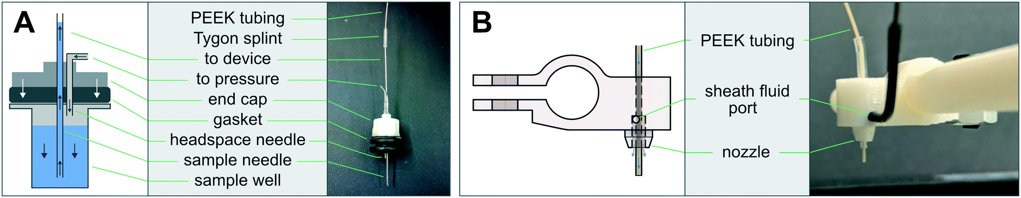 | ||
| Fig. 3 (A) Diagram and corresponding image of the dual-lumen ‘sipper’ needle. A rubber gasket seals the needle assembly against a multiwell plate, allowing air pressure applied to the headspace to drive fluid into the sample needle and subsequently onto the device. (B) Diagram and image of the sheath nozzle, which cleanses the tubing outlet after sample collection with a coaxial sheath fluid (e.g. air, water, or oil). | ||
To ensure that samples remain stably fixed in place, multiwell plates are attached to the XY-stage via 3D-printed deck components (files compatible with the ASI MS-2000 are provided in the micrIO GitHub repository;† see Fig. 2A: k). The primary deck guides form a slot which accommodates any ANSI/SLAS standard multiwell plate, while a 4 × 20 mL rack secures scintillation vials to hold and collect larger volumes of fluids.
3.3 Fraction Collector
Multiplexed sample output leverages the full capabilities of on-chip automation to prepare fractions and collect each in a separate output receptacle. Similar to the AutoSipper, the Fraction Collector positions the outlet line directly above the selected well by using an XY-stage to translate the destination plate beneath the outlet tubing (Fig. 2B). However, the Fraction Collector lacks the need for a motorized Z-assembly; we found that the Fraction Collector can reliably deposit drops of effluent into target receptacles (as small those in a 384-well plate) by statically positioning the outlet tubing 2–3 mm above them. To flush the outside surface of the outlet tubing and minimize ‘hanging drops’ that could produce cross-contamination, the Fraction Collector features a simple dropper assembly in which the effluent outlet is coaxially centered within a 3D-printed sheath nozzle that allows a low-pressure stream of fluid to rinse the edges of the tubing (e.g. with an ethanol–water wash) (Fig. 2B: g–i and 3B). This sheath flow can be left on at all times or can be temporally activated using available pneumatic control hardware (as in our implementation).3.4 Software
Both the AutoSipper and Fraction Collector may be programmed with acqpack, our open-source Python package which also enables coordinated control of devices such as microfluidic control manifolds, MFCS units, and syringe pumps (Fig. 4). Up-to-date versions are installable both via GitHub and pip, aiding in easy deployment and portability. | ||
| Fig. 4 Software architecture of the acqpack package. The evolution of two high-level commands (issued from a GUI or script) are shown as they propagate down to hardware. | ||
The acqpack package allows for high-level control of an autosampler or fraction collector, regardless of the precise hardware implementation. To accomplish this, acqpack is built with a modular architecture that allows users to build an autosampler or fraction collector with alternate hardware so long as they wrap manufacturer-specific hardware commands within a low-level class to provide a standard interface for higher-level classes (Fig. 4). Each device that interfaces with the controlling PC (i.e. the Z-motor and the XY-stage controller) has a corresponding low-level class that exposes the commonly used functions of that device. These classes map hardware-level (often serial) commands provided by the hardware manufacturer onto functions that standardize the notion of what a particular object can do (e.g. a stage can ‘home’ itself, ‘move’ by a relative number of units, or ‘move’ to an absolute position). High-level classes coordinate low-level functions and provide additional functionality not intrinsic to the lower-level classes. For instance, a high-level Autosampler class subsumes both a low-level AsiController (XY) and Motor (Z) while also managing emergent functionality expected of an Autosampler (such as coordinate frames and platemaps).
Properly addressing vessels placed on the deck of an autosampler or fraction collector requires reconciling the hardware's notion of coordinates with those of the vessels. To aid in this point registration and calibration process, acqpack allows users to specify the number of rows and columns of vessels (e.g. wells) within an array (e.g. plate) placed on the deck, along with the hardware coordinates of 3–4 vessels in the array (e.g. the top left, top right, and bottom right) so that the orientation and spacing of the array can be determined. The software then calculates the hardware coordinates of all vessels in the array and saves a platemap: a flat table of vessels, their array indices, and their hardware coordinates. The user may extend this platemap table with additional columns defining vessel properties, such as contents and names, that then become a valid means to address vessels (e.g. a FractionCollector instance can be instructed to goto a ‘waste’ vessel). The software also allows users to define and save alternate coordinate frames as transformation matrices (e.g. so that a plate may have its own origin, scaling, and orientation).
In addition to coordinate frame and platemap files, parameters for a particular device, such as the serial communication port and settings, are stored in a YAML configuration file that is loaded when a class is instantiated (rather than being hard-coded into source). This separates the procedural code from the configuration of a particular setup, enabling portability from system to system. To aid users in configuration and calibration of a new AutoSipper or Fraction Collector, associated software documentation and tutorial Jupyter notebooks guide users through setup. Graphical user interfaces (GUIs) for the AutoSipper and Fraction Collector further assist in this manual process (Fig. S2†).
While Python is all that is required for scripted control of an Autosampler and/or FractionCollector, Jupyter notebooks provide additional benefits to researchers in all stages of an experiment, including protocol development, execution, and analysis.30,31 Jupyter's cell-based format enables researchers to rapidly test and modify snippets of code before assembling them into a complete protocol notebook that can be documented with inline, formatted text cells. During execution, the notebook gives a detailed record of the procedure that the researcher can supplement with specifics and observations. Finally, the researcher can seamlessly transition to data analysis and visualization simply by adding additional cells.
3.5 Flow path configuration and characterization
When connecting the AutoSipper and Fraction Collector to a pressure-driven microfluidic device, elements of the flow path should be kept as short as possible, as this decreases both carryover and latency by linearly reducing surface area, volume, and resistance. Reducing the cross-sectional area of an element (e.g. tubing) will likewise decrease surface area and volume, although this also increases resistance (which is inversely related to the fourth-power of a tube's radius). Whether an element's increased resistance substantially increases latency in a fixed-pressure system depends on its relative contribution to the total resistance of the entire flow path (including the microfluidic device, which is often the bottleneck). Where possible, connections between fluidic elements should also have minimal volume and avoid disruptions to laminar flow.When considering the performance of a flow path under fixed pressure, two properties are useful: the volume and the volumetric flow rate. The flow path volume can usually be estimated as the sum of simple geometric formulas; for example, tubing can be modeled as a cylinder, while rectangular device channels can be modeled as cuboids. Alternatively, flow path volumes >2 μL can be empirically measured by filling the flow path with water and then pushing air through the system to displace the water into a collection tube for volumetric measurement (via pipette) or gravimetric measurement (via analytical balance). Applying the geometry-based method to one of our setups, we determined the volume of the 4 cm × 22G sample needle to be 5.36 μL, the volume of the 35 cm × 65 μm inner diameter PEEK input and output tubing to each be 1.16 μL, and the volume of the microfluidic inlet manifold to be negligible (∼5 nL), giving an end-to-end flow path volume of 7.68 μL. The volumetric flow rate determines how much time is needed for a reagent to transit a length of tubing or for a sufficient quantity of reagent to be delivered. In fixed-pressure systems the flow rate is a function of flow path resistance, fluid physical properties, and pressure. While these three factors can be modeled under assumptions such as laminar flow, in our hands it is more accurate and practical to either monitor flow rate with an inline sensor or empirically measure flow rates at given pressures. Two simple methods are to either: (1) determine the time it takes a trackable marker such as an air gap or visible dye to transit an element of known volume and divide the volume by the time, or (2) to collect effluent for a chosen amount of time, measure the volume (again by pipette or analytical balance), and divide the volume by the time.
3.6 Wash considerations
Washing procedures are highly dependent on the sensitivity of the application, the affinity of analytes for flow path elements, and the presence of specific device features. Although there is an inherent trade-off between time spent washing (throughput) and wash stringency, faster yet effective washes can be achieved by optimizing the flow path and using wash reagents tailored to the application (e.g. detergents or organic solvents for hydrophobic molecules, nucleases for nucleic acids, and proteases for proteins). Similarly, the surface of flow path elements may be modified with an anti-fouling reagent (blocking protein, surfactant, hydrophobic coating, etc.) or substituted with more inert materials. Here, we washed with a solution of Pluronic F-127, a surfactant which has previously been used to solubilize dye molecules and passivate the surfaces of microfluidic devices.32,33 Certain features of microfluidic devices, such as the valved wash and waste ports of the microfluidic inlet manifold and bead generator used here, can also facilitate rapid device washing as well as simultaneous flushing of input and output tubing. For devices lacking valved ports, a simple alternative is to perform blank sample injections as necessary.3.7 Delay time determination
Once the flow path configuration, run pressures, and wash procedure are set, the times necessary to prime the flow path until it is filled with a new sample and to wash the flow path until the previous sample is thoroughly removed must be determined (Fig. 5A). Where relevant, the delay time required to collect a desired volume of sample must also be determined. Although these delay times can be estimated when flow path volumes and flow rates are known, we demonstrate here how to empirically measure these times for an example setup in which the AutoSipper and Fraction Collector are connected to a microfluidic inlet manifold. | ||
| Fig. 5 Determination and validation of MicrIO delay times and wash procedures. (A) Cartoon depicting how to determine the delay times necessary to [1] prime a flow path with sample and [2] wash the flow path to prepare for the next sample. (B) Workflow to validate that priming times are sufficient to repeatably introduce samples to a device and confirm the wash procedure sufficiently reduces carryover. (C–E) Per-well concentrations of: fluorophore in the device during ‘collect’ phases, estimated by the mean RFU measured by epi-fluorescence microscopy; fluorophore in the output plate, estimated by RFU as measured by plate fluorimetry; and DNA in the output plate, estimated by Cq as measured by qPCR. Top lines indicate the maximum expected concentration, while bottom lines indicate the apparent concentration of known blank samples. See Fig. S1† for standard curves. | ||
Before measuring prime times, we set input pressures (AutoSipper and wash) to 15 psi and flushed the entire flow path with wash solution. We then monitored the device inlet channel via epi-fluorescence microscopy while the AutoSipper introduced a fluorescent dye (25 μM sulforhodamine-B) and the inlet manifold directed input flow to waste (Fig. 5A). The fluorescence signal plateaued after 175 s (Fig. 5B), indicating that the input tubing was primed. We then switched the inlet manifold to flow the dye to the Fraction Collector and observed by eye that the dye front transited the output tubing in 55 s, giving a total prime time of 230 s. To determine the time required to collect 10 μL, we continued to flow through the outlet for a chosen amount of time (3.50 minutes) while effluent was collected into a snap-cap tube. We measured this volume at 9 μL by pipette, giving a calculated flow rate of 2.58 μL min−1 and indicating 3.88 minutes were required to collect the target volume of 10 μL. Finally, we determined the time required to wash the flow path by moving the AutoSipper and Fraction Collector to waste positions and simultaneously flushing the input and output with wash solution distributed by the microfluidic inlet manifold. Since the volume of the input (needle and tubing) was larger than the volume of the output (tubing only), we observed by eye the time required for the backflushed effluent at the AutoSipper to turn colorless, yielding a time of 75 s. To remove any trace sample bound to the surface of the flow path, we multiplied this time by 3 to yield a conservative wash time of 3.75 min; subsequent priming of a blank sample confirmed that negligible fluorescence was measured within the microfluidic inlet manifold (Fig. 5B). An example notebook to determine delay times is included in the ESI.†
3.8 Validation of timing and washing
To quantitatively measure carryover of two analytes over the course of repeated sampling, we connected the AutoSipper and Fraction Collector to the microfluidic inlet manifold as above and transferred a 12-well alternating sequence of blank samples (water) and positive samples (fluorophore and DNA) from an input plate to an output plate such that the detection of positive sample within a blank sample would clearly indicate carryover (Fig. 5). Additionally, we quantitatively tested to what extent input needle washing and output sheath flow reduce carryover by transferring two more identical 12-well sequences in which each feature was individually turned off. The concentrations of fluorophore (25 μM sulforhodamine-B) and DNA (1 pM) in the positive sample were selected such that they were within the linear range of all techniques (epi-fluorescence microscopy, plate reader fluorimetry, and qPCR), and several standard curves with known blanks (Fig. S1†) were included to enable back-calculation of concentrations (Fig. 5C–E). During operation, the platform iteratively: (1) primed the microfluidic inlet manifold and collector tubing with an input sample from a 96-well plate, (2) collected 10 μL of sample into a corresponding output well of a 96-well plate, and (3) backflushed the input tubing and forward flushed the output tubing with wash solution. To distinguish between carryover from the microfluidic device and carryover from the AutoSipper and Fraction Collector, we measured the concentration of positive sample at two points along the flow path: on the microfluidic device with epi-fluorescence microscopy, and in the collected output plate with a fluorescence plate reader and qPCR (Fig. 5B).Over the 48 injections (3 × 12-well sequences of alternating samples and 1 × 12-well internal standard curve), the average throughput was 1 sample processed every 12.5 minutes (∼5 samples per hour). When both a needle wash and sheath flow were used, the RFU and Cq of blank injections were nearly indistinguishable from known blanks, representing a ∼4-order of magnitude reduction in both fluorophore and DNA concentration relative to the positive sample (Fig. 5B). These experiments highlight the importance of washing the outside of the AutoSipper needle for sensitive applications, as evidenced by an increase in epi-fluorescence signal during the no-needle wash sequence (Fig. 5C). The amount of fluorophore collected across positive sample injections was consistent and demonstrated good sample recovery (Fig. 5D); recovery of DNA was slightly less consistent, although analysis was confounded by the error introduced by additional low-volume pipetting steps (Fig. 5E).
3.9 micrIO validation: spectrally encoded bead synthesis
Demonstrating the utility of the AutoSipper and Fraction Collector additionally requires showing that the platform can reliably: (1) sample from all wells of a 96-well input plate, (2) form a stable pressure seal to push samples through to a microfluidic device, (3) collect samples into specified output receptacles located throughout a collection rack, (4) perform these tasks without cross-contamination between samples, and (5) do all of these tasks in a programmable, automated manner.Microfluidic bead generation provides an excellent test application for the AutoSipper and Fraction Collector. First, many labs across the world generate droplets using microfluidic T-junction or flow focusing devices for a variety of applications,34 including single-cell genomics,35 high-throughput protein screening,36,37 and digital droplet PCR.38,39 Second, generation of microfluidic droplets containing spectrally distinct materials allows detection of minute amounts of carryover during both input (which would manifest as a drift in bead code) and output (which would manifest as beads of a certain code being collected into the wrong receptacle). Lastly, monodisperse droplet formation requires stable input pressure and flow, and so bead size distribution can serve as a proxy for the ability of the AutoSipper to form a robust connection with the sample well.40 We therefore fabricated a microfluidic droplet generator in which an aqueous flow meets an oil flow at a simple T-junction, causing the aqueous flow to pinch off and form droplets.25 The aqueous flow channel includes 2 inlets controlled by on-chip pneumatic valves, making it possible to prime the device with a particular material by directing flow from the inlet to a waste outlet just before the T-junction (Fig. 6B); similarly, this architecture allows for stringent channel washing between injections by directing flow from the wash inlet to the waste outlet.
 | ||
| Fig. 6 Validation of the AutoSipper and Fraction Collector using spectrally encoded bead synthesis as the test application. (A) Photographs (inset) and emission spectra for 3 lanthanide yttrium orthovanadate nanophosphor (LN) species under UV excitation (292 nm): europium (left), dysprosium (middle), and samarium (right). The bandpass filter regions used to distinguish these LNs (620 nm, 572 nm, and 650 nm, respectively) are shown in the background. (B) Cartoon showing experimental setup. LN-prepolymer mixtures positioned in 9 wells across a 96-well plate were introduced into a microfluidic droplet generator via the AutoSipper. The droplets produced on-device were polymerized into solid beads via exposure to UV light. Each batch of beads was output to individual wells of a multiwell plate using the Fraction Collector. (C) Example multi-channel images of beads from wells H10, H11, and H12 containing putative Eu, Dy, and Sm beads, respectively. (D) Per-channel intensity of each bead (894 total). (E) Distribution of bead sizes for each well. | ||
To generate spectrally encoded beads, we employed 3 species of LNs (Eu:YVO4, Sm:YVO4, and Dy:YVO4) that can be excited at a single wavelength (292 nm) yet emit visible light in well-separated spectral bands, making it easy to distinguish one from another by imaging with specific bandpass filters (Fig. 6A). To demonstrate that the AutoSipper can reliably sample across its mechanical range, each LN-prepolymer mixture was deposited in triplicate within wells spaced across a 96-well input plate. We then programmed the AutoSipper to sample from each of these wells in series and push the LN-prepolymer mixture through the microfluidic device to form prepolymer droplets. These droplets were polymerized on-chip with a UV light source, and the Fraction Collector deposited the resulting bead batches into separate collection receptacles in serpentine fashion (Fig. 6B).
To reduce carryover, the AutoSipper was programmed to cleanse the sample line and needle between injections by directing a wash solvent to flow from the bead generator wash inlet back through the AutoSipper inlet tubing. The outside of the dual-lumen needle was also cleaned by dipping into separate scintillation vials containing strong (isopropyl alcohol) and weak (water) wash solvents, and the outlet line was given ample time to clear itself of remaining beads. Each well was processed in ∼7.9 min, comprising ∼45 s of priming, 5.7 min of generating/collecting droplets, and ∼1.4 min of washing (timestamped log files are available in the supplemental GitHub repository†). Once collected, we imaged the beads deposited in each well under UV excitation and filtered emission with 3 bandpass filters to discriminate between the 3 LN species with some inherent cross-talk (Fig. 6C). Image intensity analysis of ∼100 beads per well (894 total) revealed 3 distinct bead clusters with variation almost solely corresponding to scaling of the 3-channel intensity ratios, suggesting negligible cross-contamination (code-drift) between injections (Fig. 6D and S3†). No beads were observed to have been collected into the wrong well, establishing a lower limit on the mis-collection rate of 1/894 ≈ 0.1%. The beads also exhibited a tight size distribution, with an overall coefficient of variation of ∼4.2%, as well as little well-to-well variability (Fig. 6E).
4 Conclusions
The potential throughput of microfluidics is often limited by the technical challenges associated with multiplexing and demultiplexing off-chip inputs and outputs, thereby constraining the number of samples and conditions that can be probed. Several papers have addressed this via microfluidic large-scale integration that incorporates thousands of pneumatic valves;16,17,19 however, this is technologically challenging to implement. In this paper, we present an open-source hardware and software platform that addresses this challenge by providing direct compatibility between standard multiwell plates and simple microfluidic devices. This setup is easy to build, relatively low-cost, and easily configurable. In this implementation, we build on recent efforts to leverage decommissioned Illumina sequencers for low-cost automation and hardware sourcing;41–48 however, the modular software architecture makes it possible to substitute any mechatronic component so long as its hardware-level commands have been wrapped in a low-level Python class to provide a consistent interface. While several open-source autosamplers and Fraction Collectors have been developed for applications such as spectroscopy and gas chromatography,49–51 the field of microfluidics has relatively few examples of autosampler and Fraction Collector usage, with the majority of these examples employing commercial solutions.52–57More recent work has demonstrated a fully automated, low-cost open-source autosampler for microfluidics that is compatible with gravity- and vacuum-driven flow.58 The ability to sample with positive, pressure-driven flow builds on the advances of this platform. In comparison to gravity-driven flow, pressure-driven flow can feasibly access higher pressures (15 psi is equivalent to a 10.5 m water column) and can be dynamically changed by programmable controllers. Vacuum-driven flow (and, similarly, flow induced by pulling on the outlet with a syringe) creates negative pressure within the flow path relative to atmosphere, which can drive bubble formation by encouraging dissolved gasses to precipitate and inducing air to diffuse through PDMS and into flow channels. The key advance to enabling positive-pressure sampling for microfluidics, a gasketed dual-lumen injector, was first implemented on a sampler with a manual XY-stage.39,59–63 The micrIO platform merges these two advances in open-source automation and positive-pressure sampling into a single platform, additionally providing fraction collection capabilities and an extensive Python package to coordinate with other devices commonly used in microfluidics. To encourage widespread adoption, we provide extensive documentation and build information (see the micrIO GitHub repository†).
The micrIO platform is compatible with a wide variety of simple PDMS devices, and it requires only a mechanism to drive fluid flow. Here, we have integrated the AutoSipper and Fraction Collector with two microfluidic devices designed for pressure-driven flow via a regulated pressure source (e.g. a computer-controlled regulator, a voltage-controlled solenoid valve, or regulated house air source). This pressure-driven flow configuration shares infrastructure with devices containing integrated on-chip pneumatic valves, allowing fully automated long-term operation with complete flushing of sample lines and device channels between sample loading. However, we anticipate the AutoSipper and Fraction Collector will be broadly useful for simple valveless devices that use syringe pumps to set fluid flow rates, especially in light of several recently published open-source syringe pump builds.40,64–67 In this configuration, the dual-lumen needle can be vented to ambient pressure (or replaced with a conventional needle), and the device itself is mounted on the AutoSipper deck. After moving the needle to the correct well, the syringe pump withdraws fluid into connected tubing. The AutoSipper then inserts the needle into a device inlet port and the syringe pump drives fluid from the tubing into the device. This capability is enabled by the sub-micron resolution and repeatability of the XY-stage and has the potential to greatly simplify droplet generation screens and workflows for high-throughput single-cell sequencing applications, among others.68 By adding a simple microscope and computer vision to a similar syringe pump-driven setup, the platform could further function as an automated colony or cell picker.69 The flexibility of micrIO to meet different challenges in lab is enabled by the modular, open-source nature of its control software and build, and we hope that the community will continue to expand its utility through the design of additional deck components and adaptation of the software to control alternate hardware.
5 Author contributions
S. A. L. and P. M. F. conceptualized the platform and validation experiment and contributed equally to the preparation of the manuscript. S. A. L. designed and built the platform, coded the hardware control software, performed the validation experiment, and coded the image analysis pipeline. P. M. F. provided funding, resources, mentorship, and project supervision.Conflicts of interest
There are no conflicts to declare.Acknowledgements
This work was supported by NIH grants 1DP2GM123641 and R01GM107132. P. M. F. is a Chan Zuckerberg Biohub Investigator and acknowledges the support of a Sloan Research Foundation Fellowship. The authors would like to thank C. Layton for helpful discussions concerning Illumina GAIIx components, M. L. Salit for helpful discussions concerning limits of detection, K. Brower for guidance with spectrally encoded bead synthesis, and A. K. White for guidance with bead synthesis, bead imaging, and manuscript revision.References
- S. J. Maerkl and S. R. Quake, Science, 2007, 315, 233–237 CrossRef CAS PubMed.
- J. Chamoun, A. Pattekar, F. Afshinmanesh, J. Martini and M. I. Recht, Lab Chip, 2018, 18, 1581–1592 RSC.
- T. Alkayyali, T. Cameron, B. Haltli, R. Kerr and A. Ahmadi, Anal. Chim. Acta, 2019, 1053, 1–21 CrossRef CAS PubMed.
- H. Huang, Y. Yu, Y. Hu, X. He, O. B. Usta and M. L. Yarmush, Lab Chip, 2017, 17, 1913–1932 RSC.
- V. Lecault, A. K. White, A. Singhal and C. L. Hansen, Curr. Opin. Chem. Biol., 2012, 16, 381–390 CrossRef CAS PubMed.
- G. Luo, L. Du, Y. Wang, Y. Lu and J. Xu, Particuology, 2011, 9, 545–558 CrossRef CAS.
- R. E. Gerver, R. Gomez-Sjoberg, B. C. Baxter, K. S. Thorn, P. M. Fordyce, C. A. Diaz-Botia, B. A. Helms and J. L. DeRisi, Lab Chip, 2012, 12, 4716–4723 RSC.
- C. M. Pandey, S. Augustine, S. Kumar, S. Kumar, S. Nara, S. Srivastava and B. D. Malhotra, Biotechnol. J., 2017, 13, 1700047 CrossRef PubMed.
- S. Quake, 2018, arXiv:1802.05601.
- A. M. Streets and Y. Huang, Biomicrofluidics, 2013, 7, 011302 CrossRef PubMed.
- M. I. Mohammed, S. Haswell and I. Gibson, Procedia Technol., 2015, 20, 54–59 CrossRef.
- M. Chabert, K. D. Dorfman, P. de Cremoux, J. Roeraade and J.-L. Viovy, Anal. Chem., 2006, 78, 7722–7728 CrossRef CAS.
- Y. Temiz, R. D. Lovchik, G. V. Kaigala and E. Delamarche, Microelectron. Eng., 2015, 132, 156–175 CrossRef CAS.
- K. Kawai, K. Arima, M. Morita and S. Shoji, J. Micromech. Microeng., 2015, 25, 065016 CrossRef.
- H. Gong, A. T. Woolley and G. P. Nordin, Biomicrofluidics, 2019, 13, 014106 CrossRef.
- T. Thorsen, S. J. Maerkl and S. R. Quake, Science, 2002, 298, 580–584 CrossRef CAS.
- J. Melin and S. R. Quake, Annu. Rev. Biophys. Biomol. Struct., 2007, 36, 213–231 CrossRef CAS.
- R. Gomez-Sjoberg, A. A. Leyrat, D. M. Pirone, C. S. Chen and S. R. Quake, Anal. Chem., 2007, 79, 8557–8563 CrossRef.
- I. E. Araci and S. R. Quake, Lab Chip, 2012, 12, 2803–2806 RSC.
- X. Li, J. C. Brooks, J. Hu, K. I. Ford and C. J. Easley, Lab Chip, 2017, 17, 341–349 RSC.
- K. Brower, R. R. Puccinelli, C. J. Markin, T. C. Shimko, S. A. Longwell, B. Cruz, R. Gomez-Sjoberg and P. M. Fordyce, HardwareX, 2018, 3, 117–134 CrossRef.
- H. Q. Nguyen, B. C. Baxter, K. Brower, C. A. Diaz-Botia, J. L. DeRisi, P. M. Fordyce and K. S. Thorn, Adv. Opt. Mater., 2017, 5, 1600548 CrossRef.
- M. Geertz, S. Rockel and S. J. Maerkl, in Synthetic Gene Networks: Methods and Protocols, ed. W. Weber and M. Fussenegger, Humana Press, Totowa, NJ, 2012, pp. 107–123 Search PubMed.
- P. M. Fordyce, D. Pincus, P. Kimmig, C. S. Nelson, H. El-Samad, P. Walter and J. L. DeRisi, Proc. Natl. Acad. Sci. U. S. A., 2012, 109, E3084–E3093 CrossRef CAS.
- K. Brower, A. K. White and P. M. Fordyce, J. Visualized Exp., 2017, e55276–e55276 Search PubMed.
- A. D. Edelstein, M. A. Tsuchida, N. Amodaj, H. Pinkard, R. D. Vale and N. Stuurman, J. Biol. Methods, 2014, 1, e10 CrossRef.
- H. Q. Nguyen, K. Brower, B. Harink, B. Baxter, K. S. Thorn and P. M. Fordyce, in Microfluidics, BioMEMS, and Medical Microsystems XV, ed. B. L. Gray and H. Becker, Proc. SPIE, 2017, vol. 10061, p. 100610Z Search PubMed.
- B. Harink, H. Nguyen, K. Thorn and P. Fordyce, PLoS One, 2019, 14, e0203725 CrossRef CAS PubMed.
- J. A. White and A. M. Streets, HardwareX, 2018, 3, 135–145 CrossRef PubMed.
- T. Kluyver, B. Ragan-Kelley, F. Perez, B. Granger, M. Bussonnier, J. Frederic, K. Kelley, J. Hamrick, J. Grout, S. Corlay, P. Ivanov, D. Avila, S. Abdalla and C. Willing, in Positioning and Power in Academic Publishing: Players, Agents and Agendas, ed. F. Loizides and B. Schmidt, IOS Press, 2016, pp. 87–90 Search PubMed.
- J. M. Perkel, Nature, 2018, 563, 145–146 CrossRef CAS PubMed.
- L. B. Cohen, B. M. Salzberg, H. V. Davila, W. N. Ross, D. Landowne, A. S. Waggoner and C. H. Wang, J. Membr. Biol., 1974, 19, 1–36 CrossRef CAS PubMed.
- V. N. Luk, G. C. Mo and A. R. Wheeler, Langmuir, 2008, 24, 6382–6389 CrossRef CAS PubMed.
- S. Zeng, X. Liu, H. Xie and B. Lin, in Microfluidics, ed. B. Lin, Springer, Berlin, Heidelberg, 2011, vol. 304, pp. 69–90 Search PubMed.
- A. K. Price and C. T. Culbertson, Anal. Chem., 2007, 79, 2614–2621 CrossRef CAS.
- P. S. Dittrich, M. Jahnz and P. Schwille, ChemBioChem, 2005, 6, 811–814 CrossRef CAS.
- F. Courtois, L. F. Olguin, G. Whyte, D. Bratton, W. T. S. Huck, C. Abell and F. Hollfelder, ChemBioChem, 2008, 9, 439–446 CrossRef CAS.
- A. C. Hatch, J. S. Fisher, A. R. Tovar, A. T. Hsieh, R. Lin, S. L. Pentoney, D. L. Yang and A. P. Lee, Lab Chip, 2011, 11, 3838–3845 RSC.
- T.-H. J. Wang, K. Hsieh, H. C. Zec, L. Liu, A. M. Kaushik and Y. Yun, US Pat., 10041112B2, 2018 Search PubMed.
- A. S. Booeshaghi, E. da Veiga Beltrame, D. Bannon, J. Gehring and L. Pachter, bioRxiv, 2019, 521096.
- J. M. Perkel, Nature, 2018, 559, 643–645 CrossRef CAS.
- R. Nutiu, R. C. Friedman, S. Luo, I. Khrebtukova, D. Silva, R. Li, L. Zhang, G. P. Schroth and C. B. Burge, Nat. Biotechnol., 2011, 29, 659–664 CrossRef CAS.
- J. D. Buenrostro, C. L. Araya, L. M. Chircus, C. J. Layton, H. Y. Chang, M. P. Snyder and W. J. Greenleaf, Nat. Biotechnol., 2014, 32, 562–568 CrossRef CAS.
- J. M. Tome, A. Ozer, J. M. Pagano, D. Gheba, G. P. Schroth and J. T. Lis, Nat. Methods, 2014, 11, 683–688 CrossRef CAS.
- N. Svensen, O. B. Peersen and S. R. Jaffrey, ChemBioChem, 2016, 17, 1628–1635 CrossRef CAS.
- E. A. Boyle, J. O. L. Andreasson, L. M. Chircus, S. H. Sternberg, M. J. Wu, C. K. Guegler, J. A. Doudna and W. J. Greenleaf, Proc. Natl. Acad. Sci. U. S. A., 2017, 114, 5461–5466 CrossRef CAS.
- W. R. Becker, I. Jarmoskaite, K. Kappel, P. P. Vaidyanathan, S. K. Denny, R. Das, W. J. Greenleaf and D. Herschlag, bioRxiv, 2019, 571588.
- C. J. Layton, P. L. McMahon and W. J. Greenleaf, Mol. Cell, 2019, 73, 1075–1082 CrossRef CAS.
- M. C. Carvalho and B. D. Eyre, Methods Oceanogr., 2013, 8, 23–32 CrossRef.
- M. C. Carvalho, C. J. Sanders and C. Holloway, HardwareX, 2018, 4, e00040 CrossRef.
- M. C. Carvalho and R. H. Murray, HardwareX, 2018, 3, 10–38 CrossRef.
- J. Clausell-Tormos, A. D. Griffiths and C. A. Merten, Lab Chip, 2010, 10, 1302–1307 RSC.
- S. Vyawahare, A. D. Griffiths and C. A. Merten, Chem. Biol., 2010, 17, 1052–1065 CrossRef CAS.
- O. J. Miller, A. El Harrak, T. Mangeat, J.-C. Baret, L. Frenz, B. El Debs, E. Mayot, M. L. Samuels, E. K. Rooney, P. Dieu, M. Galvan, D. R. Link and A. D. Griffiths, Proc. Natl. Acad. Sci. U. S. A., 2011, 109, 378–383 CrossRef.
- S. Idinyang, PhD thesis, University of Nottingham, 2017 Search PubMed.
- D. Bazopoulou, A. R. Chaudhury, A. Pantazis and N. Chronis, Sci. Rep., 2017, 7, 9403 CrossRef.
- B. Wouters, B. W. J. Pirok, D. Soulis, R. C. Garmendia Perticarini, S. Fokker, R. S. van den Hurk, M. Skolimowski, R. A. H. Peters and P. J. Schoenmakers, Anal. Chim. Acta, 2019, 1053, 62–69 CrossRef CAS PubMed.
- R. C. Lagoy and D. R. Albrecht, Sci. Rep., 2018, 8, 6217 CrossRef PubMed.
- T. D. Rane, H. C. Zec and T.-H. Wang, J. Lab. Autom., 2012, 17, 370–377 CrossRef.
- H. Zec, T. D. Rane, W.-C. Chu and T.-H. Wang, in Proceedings of the ASME 2012 10th International Conference on Nanochannels, Microchannels, and Minichannels, ASME, 2012, vol. 44793, pp. 91–96 Search PubMed.
- H. Zec, PhD thesis, Johns Hopkins University, 2015 Search PubMed.
- T.-H. Wang, T. D. Rane and H. C. Zec, US Pat. App., 20160332163A1, 2016 Search PubMed.
- T.-H. Wang, T. D. Rane, H. C. Zec and W.-C. Chu, US Pat., 10222391B2, 2019 Search PubMed.
- B. Wijnen, E. J. Hunt, G. C. Anzalone and J. M. Pearce, PLoS One, 2014, 9, e107216 CrossRef.
- J. R. Lake, K. C. Heyde and W. C. Ruder, PLoS One, 2017, 12, e0175089 CrossRef.
- M.-C. Chen, J. R. Lake, K. C. Heyde and W. C. Ruder, J. Visualized Exp., 2018, e57532 Search PubMed.
- V. E. Garcia, J. Liu and J. L. DeRisi, HardwareX, 2018, 4, e00027 CrossRef.
- N. Shembekar, C. Chaipan, R. Utharala and C. A. Merten, Lab Chip, 2016, 16, 1314–1331 RSC.
- T. Hartley, C. Stewart, R. Stewart and D. J. Munroe, JALA, 2009, 14, 22–26 Search PubMed.
Footnotes |
| † Electronic supplementary information (ESI) available. See DOI: 10.1039/c9lc00512a |
| ‡ Build files, code, and data available in GitHub repository: https://github.com/FordyceLab/micrio. |
| This journal is © The Royal Society of Chemistry 2020 |