
 Open Access Article
 This Open Access Article is licensed under a Creative Commons Attribution-Non Commercial 3.0 Unported Licence
Merits of microwave plasmas for optical emission spectrometry – characterization of an axially viewed microwave-sustained, inductively coupled, atmospheric-pressure plasma (MICAP)†
Helmar
Wiltsche
 *a and
Matthias
Wolfgang
b
*a and
Matthias
Wolfgang
b
aGraz University of Technology, Institute of Analytical Chemistry and Food Chemistry, Graz, Austria. E-mail: helmar.wiltsche@tugraz.at
bResearch Center Pharmaceutical Engineering GmbH, Graz, Austria
First published on 12th August 2020
Abstract
Considerable technological improvements in the field of microwave plasma technology intrigued us to reconsider this technology as a promising alternative to inductively coupled plasma (ICP) as an emission source for analytical spectrometry. We have investigated and characterized the analytical capabilities of an axially viewed microwave-sustained, inductively coupled, atmospheric-pressure plasma (MICAP) as a potential emission source for spectrometry. In combination with the spectrometer part of a commercial inductively coupled plasma optical emission spectrometer (ICP-OES), limits of detection (LOD) and limits of quantification (LOQ) for 30 elements based on 72 emission lines were determined and compared to ICP as the reference emission source. LODs for MICAP were about a factor of ten higher than those obtained by ICP-OES when using the same spectrometer, detector and data processing software. However, the magnitude of LOD degradation was strongly dependent on the element, the emission line and the excitation energy of the transition. In comparison with a commercially available magnetically excited (Hammer cavity) microwave plasma-optical emission spectrometer (MIP-OES), the LODs were similar with the exception of Ni and Pb. For these elements, lower LODs were attained with the Hammer cavity based instrument due to the more elaborate algorithms available in the control software for background correction and subtraction of the highly structured nitrogen plasma background. The impact of the used plasma gas was investigated for the MICAP with a special focus on air as the sole plasma gas, emphasizing the capabilities of this approach for cost-effective operation, when LODs are not the prime requirement.
Introduction
Inductively coupled plasma (ICP) as an analytical emission source evolved from the initial experiments conducted by Reed1 in 1961 into a widely used plasma source for atomic spectrometry today. Though extensively used in commercial instruments, ICP is certainly not the only plasma source available for analytical atomic spectrometry.In fact, the history of microwave induced plasmas (MIP) started about ten years earlier in 1951, with the first groundbreaking work on microwave-generated plasma by Cobine and Wilbur.2 They had already used magnetrons for generating the necessary microwave radiation, developed a torch for a plasma discharge that would later be called a capacitively coupled microwave plasma (CMP) and studied the suitability of Ar, He, CO2, N2 and air as plasma gasses. Other authors, such as Mavrodineanu and Hughes,3 realized the potential for spectrochemical analysis and recorded the emission spectra of various elements.
In 1975 Moisan, Beaudry and Leprince4 reported on a high frequency (HF; 500 MHz) driven low pressure plasma source using argon as the plasma gas. Though the source was initially driven at low power (<100 W), the authors were able to show that the plasma could be sustained at much higher power (500 W) and at frequencies up to the L band (1–2.6 GHz). In fact, their work can be considered the nucleus of what would become the Surfatron cavity.
Only one year later, in 1976 Beenakker5 developed a disk-shaped discharge chamber, able to sustain an argon or helium MIP at atmospheric pressure at relatively low power (<200 W) – the Beenakker cavity. Although initially operated only with noble gasses, the Beenakker cavity can also be operated with molecular gases such as nitrogen or even air when the microwave power level is raised to about 500 W (ref. 6) and the cavity is slightly modified.7 Moreover, it is possible to introduce an aqueous aerosol without desolvation.
A unifying property of all the cavities listed above is their limited ability for high power (>1000 W) operation. The first high-power cavity reported in literature was developed by Okamoto8,9 in 1990 – the Okamoto cavity. The driving forces towards higher microwave power were the interest in nitrogen as a plasma gas, as argon and particularly helium are much more expensive than nitrogen. Moreover, high-power plasmas can dry and excite aqueous aerosols more effectively and suffer less from matrix-induced non-spectral interference. In fact, the referenced and often cited work on the Okamoto cavity is an extension of Okamoto's initial work on a plasma excited by circularly polarized microwave radiation.10–12 This peculiar field geometry was attained by using a helical coil – much like the load coil of an ICP. The Okamoto cavity was used in a commercially available microwave induced plasma-mass spectrometer (MIP-MS) from 1990 to 2004.9,13–15
In 2004 Varian Ltd. took out a patent16 on a magnetically excited plasma source – the Hammer cavity. As later outlined by Hammer,17,18 this cavity relies on the placement of the plasma torch inside a microwave waveguide in such a way that the magnetic field is axial to the axis of the torch. By using an iris blind, the traversing electrical field is distorted inside the torch, resulting in an annular-shaped plasma discharge using nitrogen as the plasma gas. Based on this principle, a commercial microwave induced plasma-optical emission spectrometer (MIP-OES) is currently available from Agilent Technologies Inc. It is interesting to note that Agilent Technologies Inc., who acquired Varian Ltd. in 2010, continued to perform research and development on the Hammer cavity. Initially, Hammer patented a resonant iris.16,17 In a later patent it is claimed, that “the performance of the plasma source was found to be compromised if the length of the waveguide deviated even by small amounts from the optimum”.19 This is not entirely surprising, as in any resonant microwave system, small geometrical changes can result in severe changes in the field geometry and have to be compensated by appropriate field tuning. Vahidpour and Geraint20,21 therefore substantially modified the original Hammer resonant iris, to enhance the robustness of the resonant design towards geometrical changes. Furthermore, one could speculate on an interaction of the introduced sample and the field geometry in the Hammer cavity, particularly considering the fact that microwave plasmas change their size in the presence of high concentrations of alkaline elements.
The most recent contribution to the field of microwave plasmas in analytical chemistry is the microwave-sustained, inductively coupled, atmospheric-pressure plasma (MICAP) developed by Jevtic, Menon and Pikelja in 2016.22 The MICAP uses a microwave-driven dielectric resonator formed by an aluminum oxide ring. Inside this ring, a standard ICP quartz torch is installed. When this ring is exposed to microwave radiation, the ceramic dielectricum is bulk polarized and, due to the ring structure, a circular electrical field is induced. Schwartz et al.23 investigated the properties of this new MIP as a source for OES, using nitrogen as the plasma gas. They concluded that, despite the elevated, structured plasma background, the MICAP can be used for elemental analysis. For a radially viewed MICAP, the limits of detection (LOD) of several elements were about a factor of 5 to 10 higher compared with an argon ICP. Schwartz et al. also noted that the MICAP is very stable even if volatile organic solvents such as acetonitrile or methanol are introduced. Thaler et al.24 extended this work by investigating the matrix effects of high concentrations of Al and Na on Ba, Fe, K, Li, Mg, Rb, Re, and Sr. In a recent publication, Schild et al.25 coupled the MICAP to a time-of-flight mass spectrometer. The authors found that not only diatomic species such as NO+, N2+ or O2+ dominate the plasma background, but also N3+, N4+ or H2O+. However, above about m/z 60, no plasma-based polyatomic interference was observed. Compared with an ICP-TOFMS, the MICAP-TOFMS provided about 10 times higher LODs in the low mass range (m/z < 75), but comparable LODs above that range.
While a large number of publications is available for the Hammer cavity based MIP-OES (ref. 26 and the references therein), only a few authors have investigated the analytical characteristics of the MICAP source. As cited above, Schwartz et al. investigated23 the plasma background and the effect of organic solvents on the stability of the plasma discharge and provided LODs for a limited number of elements (Al, Cd, Cd, Co, Cr, Fe, Mg, Mn, Pb, Sr) determined by MICAP-OES in radial viewing.
The aim of this work is to investigate the analytical capabilities of the MICAP in axial viewing and to compare the results with those acquired by ICP-OES and additionally with a commercial Hammer cavity based MIP-OES. Limits of detection (LOD) and limits of quantification (LOQ) were used for this purpose. Moreover, the properties of an MICAP operated with air instead of nitrogen as the plasma gas are investigated.
Experimental
Instrumentation
The working principle and general setup of the MICAP plasma source used have been described comprehensively by Schwartz et al.23 Deviating from the cited work, a 1.5 kW Panasonic 2M262A magnetron and a conventional one-piece ICP-OES torch (for the Ciros Vision EOP, Spectro, Germany) with a 2.5 mm injector were used. It might be interesting to note that the high-density alumina ceramic ring inside the MICAP source is of high purity: using energy dispersive X-ray fluorescence spectrometry (EDX-8000, Shimadzu, Japan), the ring was found to contain more than 99.9% Al2O3 with calcium and iron being the main trace contaminants.The MICAP was combined with the spectrometer of a commercial, axially viewed ICP-OES (Ciros Vision EOP, Spectro, Germany), as shown in Fig. 1. Prior to installation of this new plasma source, the load coil and the RF generator were removed from the ICP-OES instrument. As the MICAP was directly bolted onto the stepper motor driven base plate, tuning of the plasma observation zone with respect to the entrance optics was easily possible with the ICP-OES instrument control software (v 2.12.0632). As this software does not enforce the ICP being ignited to operate the autosampler, spectrometer and detector, it was used for controlling the sample delivery to the MICAP, as well as for data recording and processing. Thereby, a high level of comparability of the data acquired with the two excitation sources, MICAP and ICP, was ensured. The sample introduction system comprised a standard baffled cyclonic spray chamber and a glass concentric nebulizer (Meinhard Type A).
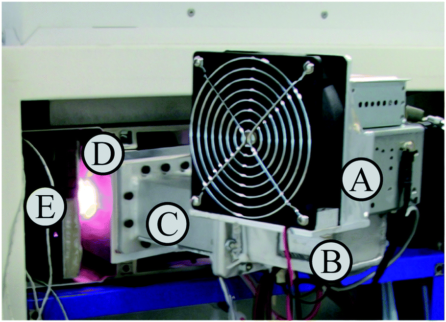 | ||
| Fig. 1 MICAP installed inside the plasma compartment of an axially viewed ICP-OES; (A) magnetron, (B) waveguide launcher, (C) waveguide, (D) MICAP cavity, (E) optical plasma interface and spectrometer. | ||
The MICAP itself and the required gas flows were controlled by a separate control unit (Radom Corp., USA), shipped with the MICAP. It is important to note that the setup did not enclose the plasma and as a consequence, microwave radiation leaked into the environment during operation. At the maximum power of 1.5 kW, the leakage measured using a RadMan 2250/56 microwave radiation monitor (Narda Safety Test Solutions, Germany) was about 0.6 mW cm−2 at a distance of 1 m. This value was considered acceptable for a lab setup as it was well below the legal limit of 5 mW cm−2. However, it should be mentioned that closer to the plasma discharge, the leakage increased and eventually exceeded the legal limit close to the surface of the MICAP setup.
For comparative measurements, an axially viewed ICP-OES (Ciros Vison EOP, Spectro, Germany) was used which allowed a head-to-head comparison between ICP-OES and MICAP, as the sample introduction system and the entire optical system were identical in both setups.
For reference purposes, a Hammer cavity MIP-OES instrument (4200 MP-AES, Agilent, USA) equipped with a cyclonic spray chamber and a glass concentric nebulizer was used. The sequential Czerny–Turner monochromator of this instrument was not nitrogen-purged, as this option was not available on the instrument used. Manual sampling was applied and the nitrogen for operating the Hammer cavity MIP-OES was generated by a separate nitrogen generator (Agilent 4107, Agilent, USA) supplied with the instrument. Signal integration time was selected based on presets in the instrument control software. The instrument was controlled using MP Expert Software (v 1.5.1.0).
The operating conditions of all three systems used are listed in Table 1.
| Parameter | MICAP | Hammer cavity MIP-OES | ICP-OES |
|---|---|---|---|
| Power, W | 1500 | 1000* | 1400 |
| Gas used to sustain the plasma | N2 | N2 | Ar |
| Outer gas flow, L min−1 | 16 | 20* | 12 |
| Intermediate gas flow, L min−1 | 0.6 | 1.5* | 0.6 |
| Nebulizer gas flow, L min−1 | 0.85 | Optimized separately for every emission line | 0.85 |
| Nebulizer type | Glass concentric | Glass concentric | Glass concentric |
| Sample flow rate, mL min−1 | 1.4 | 1.3 | 1.4 |
| Integration time, s | 24 (full spectrum) | 3 (for each emission line) | 24 (full spectrum) |
| Replicates | 5 | 5 | 5 |
| Background correction | 2 points (manual selectable) | Proprietary algorithm | 2 points (manual selectable) |
Reagents
Purified water (18 MΩ cm, Barnstead Nanopure, Thermo Fisher Scientific, USA) and high-purity acids (HNO3, Roth, Germany, purified by subboiling) were used throughout. Standard solutions were prepared from a 100 mg L−1 multi-element stock solution (Al, Ag, As, B, Ba, Be, Bi, Ca, Cd, Co, Cr, Cu, Fe, K, Li, Mg, Mn, Mo, Na, Ni, Pb, Sb, Se, Sr, Ti, Tl, V, and Zn, Roth, Germany) and 1 g L−1 single element stock solutions (As, Bi, S, Se, P; Roth, Germany) by dilution with 3% HNO3 (v/v). The ICP-OES was operated using argon (purity 99.9990%, Messer, Austria) as the plasma gas while for the MICAP nitrogen (purity 99.999%, boiled-off from a liquid nitrogen storage tank, Linde, Austria) was used.Limit of detection and limit of quantification
With the MICAP setup as well as with ICP-OES, limits of detection (LOD) and limits of quantification (LOQ) were determined for 30 elements using a total of 72 emission lines following DIN 32645:2008.27 Details of the calculation procedures are provided by Hesse et al.28 Elements routinely analyzed in our laboratory were selected for this investigation. The emission line selection was based on literature data.23,29 For As, Bi, and Se the concentration range was 0.22–1.54 mg L−1, for S and P 0.1–5.0 mg L−1 and for all other elements 0.02–0.14 mg L−1. The calibration range was covered by eight equidistant standards. LODs were calculated using the blank method and LOQs were calculated using the calibration method. The instrumental conditions listed in Table 1 were used.For comparison with the Hammer cavity instrument, LODs and LOQs of selected analytes, whose emission lines cover the relevant analytical spectral range, were recorded using the same solutions as for the MICAP setup. The selected lines are summarized in Table 2.
| Element, emission line | MICAP | Hammer cavity MIP-OES | ICP-OES | |
|---|---|---|---|---|
| LOD, μg L−1 | LOD, μg L−1 | Literature values, LOD, μg L−1 | LOD, μg L−1 | |
| Al(I) 396.152 nm | 1 | 3 | 0.3 (ref. 18) to 1.6 (ref. 34) | 2 |
| B(I) 249.773 nm | 8 | ND | 1.1 (ref. 34) | 0.8 |
| Cd(I) 228.802 nm | 10 | 10 | 4 (ref. 34) to 9.6 (ref. 18) | 1 |
| Cu(I) 324.754 nm | 4 | ND | 1.3 (ref. 18) to 2.2 (ref. 35) | 2 |
| Fe(II) 259.941 nm | 4 | ND | 4.1 (ref. 35) | 0.4 |
| K(I) 766.491 nm | 1 | ND | 1.4 (ref. 18) to 60 (ref. 36) | 6 |
| Mn(II) 259.373 nm | 1 | ND | 1.5 (ref. 35) to 4.2 (ref. 18) | 0.09 |
| Mo(I) 379.825 nm | 20 | ND | 1 (ref. 34) to 2 (ref. 18) | 6 |
| Ni(I) 352.454 nm | 60 | 10 | 2.4‡ (ref. 18) to 8.4 (ref. 34) | 5 |
| P(I) 213.618 nm | 400 | 300 | 430 (ref. 36) | 10† |
| Pb(I) 405.778 nm | 20 | 4 | 2 (ref. 34) to 5 (ref. 18) | 3¶ |
| Se(I) 196.09 nm | 500 | 500 | 67 (ref. 18) | 10 |
| Zn(I) 213.856 nm | 20 | ND | 7.6 (ref. 35) to 12 (ref. 18) | 0.9 |
Results and discussion
Optimization of the MICAP
As the MICAP was directly mounted onto the stepper motor driven base plate of the ICP-OES instrument, the position of the microwave plasma could be optimized with respect to the spectrometer's entrance slit. For the x and y adjustments, signal profiles similar to those from an ICP were obtained. ESI Fig. 1† shows the variation in emission signal of a 1 mg L−1 Mn solution as a function of the relative alignment of MICAP and spectrometer. It is evident from the figure that, within the scanned region of 2.4 mm, the emission signal varied by only 15%. This behavior can be expected for the wide-bore 2.5 mm injector of the torch and matches with alignment data acquired with the ICP. Comparable behavior was recorded for the vertical axis.The optimal axial distance between the center of the normal analytical zone (NAZ) of the plasma discharge and the spectrometer's entrance slit (z adjustment) was also investigated. This parameter can be optimized by varying the distance between the optical plasma interface (OPI; bolted onto the spectrometer) and the stepper motor driven base plate, which has the MICAP attached. In the original ICP-OES setup the distance between the OPI and the tip of the torch is approx. 9 mm. For the MICAP, no significant change in the Mn(II) 257.611 nm emission line signal was recorded when this distance was varied between 15.5 and 17 mm. Above 17 mm, the emission signal decreased (from 17.0 to 17.6 mm by 14%). Positioning the MICAP closer than 15.5 mm from the OPI resulted in an unacceptable increase in the temperature of the MICAP's aluminum case, due to the hot gases from the plasma expanding between the OPI and the MICAP case. However, only the OPI was water-cooled, resulting in heating of the MICAP's casing, when the distance between the OPI and MICAP case became too small. Consequently, all further experiments were conducted at a distance of 16 mm.
The nebulizer gas flow was optimized based on the emission intensity of a 1 mg L−1 Mn solution for the Mn(II) 257.611 nm emission line (ESI Fig. 2†). The maximum signal intensity was obtained for a nebulizer gas flow rate of 0.85 L min−1 – the same nebulizer gas flow rate which was obtained during an optimization in ICP-OES.
ESI Fig. 2† also shows the dependence of the Mn(II) 257.611 nm emission line signal of the MICAP as a function of applied microwave power (1.2 to 1.5 kW) at different nebulizer gas flows (0.7 to 1.2 L min−1). Comparable to ICP-OES, the intensity of the Mn emission line increased nearly linearly by 33% when the applied microwave power was changed from 1200 W to 1500 W. However, the plasma background increased by about 60% in the course of this power change. It is important to note that the degree of signal enhancement as a function of applied power depends strongly on the total emission line energy. Moreover, the increase in plasma background is also dependent on the observed wavelength region. All these findings obtained for the MICAP are in good agreement with the observations made in ICP-OES.
Plasma background and short-term stability
It is well known that plasma discharges formed with molecular gases such as nitrogen emit very line-rich spectra (ref. 30 and the references listed therein). This of course holds true for the MICAP, as also noted by Schwartz et al.23Fig. 2 compares the plasma background of the nitrogen-operated MICAP with that of an argon-operated ICP. Without going into specific spectral features, it is evident that the MICAP spectral background is highly structured over most parts of the analytically used spectral range, which results in spectral interference and degraded signal to noise ratios. It is interesting to note that below 160 nm the plasma background of the MICAP becomes rather small and comparable to that of the ICP. However, due to the lower ionization potential of nitrogen (14.53 eV instead of 15.75 eV for argon) no sensitive emission lines were encountered below 160 nm. Much to the contrary, in an ICP several elements have their most sensitive emission lines in the spectral region between 125 and 180 nm (e.g. Al, Br, Cl, Ga, Ge, I, In, N, P, Pb, Pt, S, and Te), as reported by Schulz and Heitland.31 It is interesting to note that with the MICAP the deep UV chlorine emission lines at 134.724 nm and 135.166 nm can be used for quantitative analysis, although their sensitivity is low when compared to the ICP: for the most sensitive line Cl(I) 134.724 nm (excitation energy 9.2 eV (ref. 32)) an LOD of 50 mg L−1 was determined using the MICAP based on the 3σ criterion. For the same line Schulz and Heitland31 report 19 μg L−1 for ICP-OES. Therefore, data on Cl have not been included in ESI Table 1† (LOD and LOD for MICAP and ICP-OES).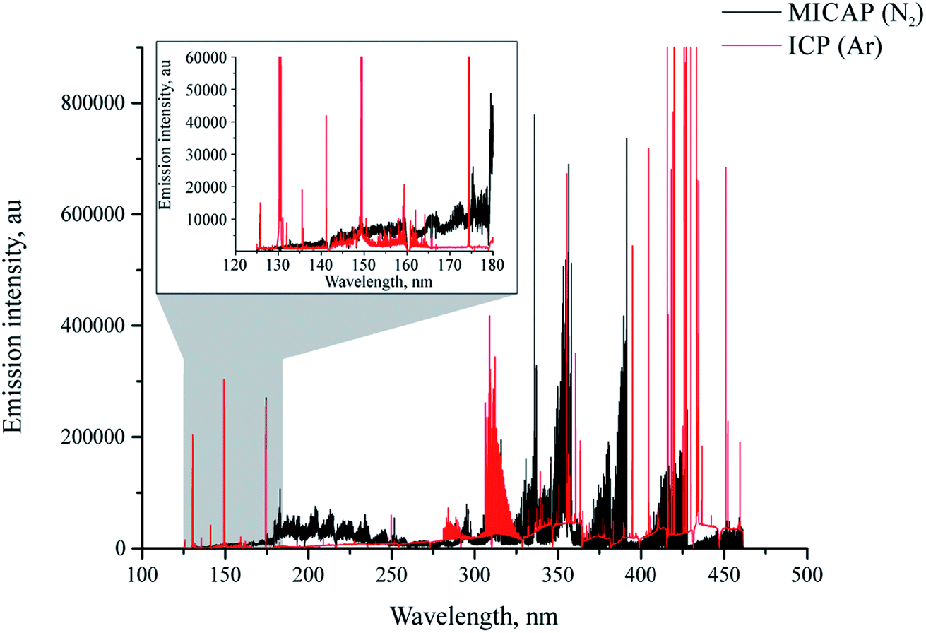 | ||
Fig. 2 Plasma background of nitrogen MICAP (black) compared to argon ICP (red) at a power level of 1400 W in the spectral region between 124 and 470 nm. Note the highly structured nature of the MICAP's plasma background compared to the argon ICP; – axis limited to 900![[thin space (1/6-em)]](https://www.rsc.org/images/entities/char_2009.gif) 000 cps for clarity. 000 cps for clarity. | ||
Spectra recorded using the Hammer cavity MIP-OES using the conditions suggested by the instrument software (refer to Table 1) initially appeared surprisingly free from the strongly structured plasma background encountered using the MICAP setup. Fig. 3 and ESI Fig. 3† illustrate these differences in an exemplary way for As(I) 193.759 nm and Zn(I) 213.856 nm.
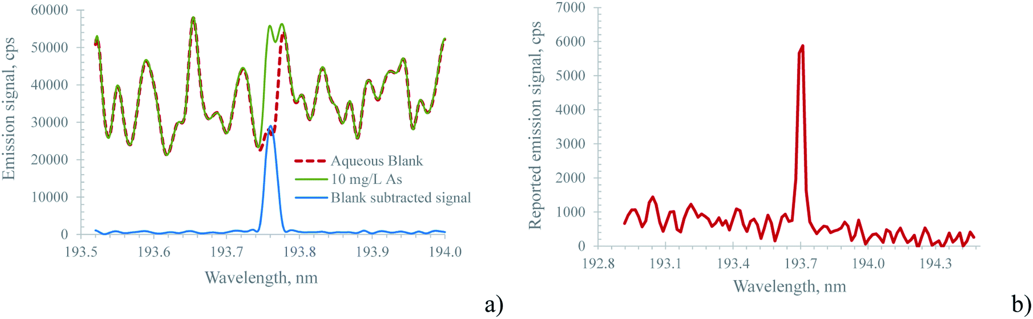 | ||
| Fig. 3 Spectrum of 10 mg L−1 As at 193.759 nm recorded with (a) the MICAP and (b) the Hammer cavity MIP-OES. The well isolated emission line of As in spectrum (b) clearly shows the effectiveness of the mathematical background subtraction performed by the instrument software. Note, that due to the different optical resolutions of the spectrometers used (18 pm for the MICAP; 30 pm for the Hammer cavity MIP-OES) the wavelength interval shown in (a) is smaller than in (b). | ||
For Zn, the MICAP spectrum shown in ESI Fig. 3b† is similar to the one published by Schwartz et al.,23 though the optical resolution of the spectrometer used in this work is only 18 pm compared to 10 pm for the one used by Schwartz.
The pronounced differences in the spectra shown in Fig. 3 and ESI Fig. 3† between the Hammer cavity MIP-OES and the MICAP were found to be based on the mathematical corrections applied by the Hammer cavity MIP-OES instrument software (MP Expert Software v 1.5.1.0), and are not rooted in different types of plasma. Chalyavi et al.33 described the algorithm as follows: “In the ‘auto’ background correction mode of the MP Expert software, models of the plasma background emission are constructed from replicate readings of blanks B, blank-subtracted standards S, and any suspected interferent species I”. This mathematically created plasma background spectrum is then subtracted from the spectrum of all standards and samples. Thereby, this background subtraction algorithm helps to isolate the analyte emission signal from the highly structured plasma background. This approach is also illustrated in Fig. 3a for the MICAP: by subtracting the blank spectrum from the sample spectrum, a well-isolated analyte emission signal is obtained. However, it is important to note that sample matrix constituents might increase the plasma continuum, rendering this very simple blank subtraction algorithm ineffective. Clearly, more elaborate procedures such as the one described by Chalyavi et al.33 are to be preferred.
The approach described above for background correction used by the Hammer cavity MIP-OES instrument raises a question about the temporal stability of this approach, particularly considering that even small wavelength drifts in the sequential monochromator might cause severe errors during the subtraction process. In order to address this question, both the MICAP and the Hammer cavity MIP-OES were tested for their short-term stability using the following procedure: first a blank solution was measured to provide the data for the ‘auto’ background correction. Thereafter, every two minutes, the spectrum of a 10 mg L−1 multi-element standard was recorded and the acquired data were normalized to the median emission intensity of every recorded emission line. This procedure was executed over approximately 3 h for the MICAP and 80 minutes for the Hammer-cavity MIP-OES. ESI Fig. 4a illustrates the results of these experiments for selected lines. While the relative signal intensity for the MICAP is remarkably stable over several hours, the experiment with the Hammer-cavity MIP-OES was aborted after 80 minutes, due to strong changes in the signal intensity of some emission lines: whereas for Mg, Pb and Zn the signal variation was within ±5%, the Se and particularly the As signals showed much larger variations over time. The Se signal variation was about 40% while the As signal dropped by a factor of 3. The reason for this behavior appears to originate in the ‘auto’ background subtraction algorithm: Fig. 4b shows the spectrum of the main As emission line at 193.759 nm. While the first reading taken immediately after the blank spectrum (the red trace in Fig. 4b) shows a well-isolated As emission line, the spectrum read after about 1.5 h (the blue, dashed trace in Fig. 4b) is highly structured, and the As vanished into the background noise. Similar behavior was encountered for blank spectra recorded over the same period with the Hammer-cavity MIP-OES at this wavelength: over time, the spectra became more and more structured and the minima in the spectra became increasingly negative. It is interesting to note that neither the background around Mg(II) 280.271 nm, Mg(I) 285.213 nm, Pb(I) 405.781 nm or Zn(I) 213.857 nm varied appreciably between the first and the last readings of the multi-element standard. Moreover, the blank spectra of these emission lines were also comparable throughout the 1.5 h stability test. This clearly indicates that the ‘auto’ background correction algorithm is only problematic in the low UV and plasma background readings should be taken in regular intervals for this spectral region. As indicated by the temporal behavior of Zn(I) 213.857 nm, emission lines above about 200 nm appear not to be affected by this problem. It should also be stated that the observed effects cannot stem from an instrumental ‘warm-up effect’. Prior to the stability measurements, the Hammer cavity MIP-OES was operated for more than 2 h.
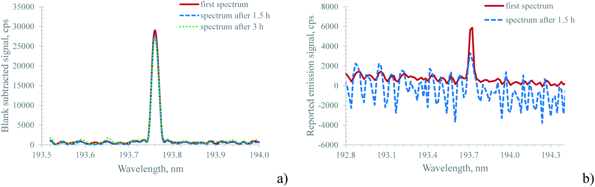 | ||
| Fig. 4 Temporal behavior of the blank subtracted spectrum of 10 mg L−1 As (193.759 nm) for (a) the MICAP and (b) the Hammer cavity MIP-OES at the beginning of a stability test (red trace) and after 1.5 h (blue, dashed trace). For the Hammer cavity MIP-OES, note the difference between the two spectra for the same solution, which indicates stability problems in the mathematical background correction algorithm. For the MICAP, the spectrum is also shown after 3 h, to illustrate the wavelength stability of the Paschen–Runge mount spectrometer. | ||
For the MICAP setup a signal drift of less than ±5% was encountered for most of the 72 investigated emission lines (ESI Fig. 4a†). Only for As(I) 189.042 nm and Be(II) 313.042 nm were the variations ±7% over a period exceeding 3 h. It is important to note that Sc(II) 361.384 nm was not used to correct signal drift in the MICAP data, as is common practice in ICP-OES. By applying internal standard correction with Sc, the variation in all recorded emission lines was below ±5% over 3 h. In fact, the largest signal drift was encountered within the first 20 minutes of the stability test. We attribute this to an insufficient instrument warm-up time of 15 minutes prior to the start of this experiment. It is interesting to note that the relative standard deviation (RSD) of the investigated emission lines ranged between 0.4 and 1.6% for the 5 detector illuminations (replicates) averaged for each stability sample. Similar RSDs were encountered in ICP-OES.
Especially when compared with the Hammer cavity MIP-OES, the blank-spectra-subtracted As(I) 193.759 nm signal of the MICAP shown in Fig. 4a was found to be very stable. Although the blank reading used for background subtraction was only taken at the beginning of the stability measurements, the difference in the As signal even after 3 h was minimal. This can be attributed to the good wavelength stability of the Paschen–Runge mount based spectrometer used for the MICAP and the ICP-OES measurements. It is important to note that the simple blank spectra subtraction approach applied to the MICAP spectra in Fig. 3a, ESI Fig. 3a† and Fig. 4a was only used to illustrate the similarity of the MICAP and Hammer cavity spectra. This simple approach was not used in the data processing of the LOD/LOQ data. The reason is the well-known matrix-dependent change in the plasma continuum intensity, which the simple spectra subtraction algorithm does not incorporate.33 Here the elaborate procedure used by the Hammer cavity MIP-OES is clearly to be preferred.
MICAP: limit of detection and limit of quantification
ESI Table 1† summarizes the LODs and LOQs for 72 investigated emission lines. In general, the LODs are comparable to those obtained by Schwartz et al.23 The main difference between the referenced data and the results listed in ESI Table 1† is that Schwartz applied ultrasonic nebulization/desolvation and radial plasma viewing to reduce the structured plasma background. In this work, simple pneumatic nebulization was used and the MICAP was viewed axially. It seems that Schwartz compensated for the sensitivity losses of radial viewing by the increased transport efficiency of the ultrasonic nebulization. Although axial plasma viewing is commonly associated with increased plasma background interference, the LODs were comparable with those obtained by Schwartz. This indicates that the highly structured plasma background cannot be effectively reduced by desolvation or radial viewing, which leads to the conclusion that, for aqueous samples, axial viewing seems to be the preferred observation mode for the MICAP.Another aspect discussed by Schwartz is that the “optimal” emission line for each element for the MICAP is not always similar to the ICP. This is not surprising, considering the different ionization energies of N2 and Ar – and thereby the maximum energy available for effectively exciting an emission line. For Pb, in ICP-OES the commonly used emission line is the 220.353 nm ion line. In a nitrogen plasma such as MICAP, this line is not effectively excited and no emission signal could be observed even for a 1 mg L−1 standard solution. Clearly, the 405.778 nm atom line is to be preferred. It is interesting to note that, contrary to reports in the literature24 the LOD of Pb was lower in ICP-OES than when using MICAP (3 μg L−1vs. 20 μg L−1 for MICAP) when using the most sensitive emission line for each plasma source (Pb(II) 220.353 nm for ICP-OES and Pb(I) 405.778 nm for MICAP). Consistent with data reported by Ohata and Furuta,13 the LODs determined by MICAP and ICP-OES were comparable when using the same emission line (Pb(I) 405.778 nm).
Schwartz23 also states, that “Generally, wavelengths that produced the strongest MICAP emission were those of ion lines”. Data listed in ESI Table 1† show a more complex pattern: consistent with reports by Ohata and Furuta13 for an Okamoto-cavity MIP, elements with an ionization energy below about 8 eV had lower LODs for ion lines than for atom lines. Above 8 eV, LODs were lower for atom lines. However, there are major exceptions to this general trend as high excitation energies of some ion lines result in degraded LODs. This effect can be observed for Al, Bi, Cu, Ni, Mo, Pb and Tl.
ESI Table 1† also lists LODs determined by ICP-OES for direct comparison with the MICAP. These data were recorded using the same spectrometer, detector and data processing software as the MICAP LODs. Therefore they represent a true head-to-head comparison between these two plasma types. When taking into account that different lines are the most sensitive ones for each excitation source, three major groups of elements can be broadly discriminated by dividing the lowest LOD obtained by MICAP for each element by the lowest LOD obtained by ICP-OES for the same element. This quotient thus represents the factor by which MICAP LODs are degraded with respect to ICP-OES.
Elements whose LODs in MICAP are no worse than by a factor of 4 in comparison to ICP-OES include the alkaline and earth alkaline elements (Be is an exception), as well as Al and Cu. The second group of elements included those whose LODs in MICAP were degraded by a factor of 5 to 15. This group includes Ag, B, Be, Bi, Fe, Mn, Mo, Pb, Sb, and Tl. LODs degraded by more than a factor of 15 were As, Cd, Co, Cr, Ni, P, S, Se, Ti, V, and Zn. When taking the median of all these data, the LODs of MICAP were a factor of 10 higher than those obtained by ICP-OES. The median was selected to express the differences in the LODs between MICAP and ICP-OES due to its inherent robustness towards extreme values in a dataset. It is important to note that, though the most sensitive lines for ICP-OES have been well known for a long time, an equally thorough investigation is still lacking for nitrogen-based plasmas such as MICAP.
MICAP: operation with air as plasma gas
Similar to the Hammer cavity18 or the Okamoto cavity,9 MICAP is able to operate with air as the only plasma-sustaining gas. After starting the MICAP using nitrogen, the plasma gas was switched over to air and LODs and LOQs were determined using the conditions listed in Table 1. The results are summarized in ESI Table 1† together with the results for nitrogen as the plasma gas in order to facilitate a direct comparison of the analytical performance for these two plasma gases. Similar to the observations made by Hammer,18 degraded analytical performance was encountered when switching from nitrogen to air. In fact, for As, Cd, Co, Cr, Fe, Mo, Ni, P, S, Se, Tl, and Zn none of the investigated emission lines showed an emission signal of the respective element above the plasma background even for the highest calibration standard concentration tested. In fact, a loose correlation with the total emission line energy was encountered: lines below about 4 eV were either not affected or even showed an improvement in the LOD (e.g. all lines of the alkaline elements). LODs of lines between 4 and 13 eV were severely degraded and in many cases no analyte emission signal above the plasma background could be recorded. Interesting exceptions are Ca II 396.847 nm and Ca II 393.366 nm where the total line energy exceeds 9 eV but the LODs were slightly improved when air was used as the plasma gas.Above the 13.5 eV total line energy no investigated analyte emission line appeared in an all-air operated MICAP spectrum, though some of these lines were encountered in an all-nitrogen MICAP. This can be explained by the fact that the first ionization energy of oxygen is 13.6 eV.
It should be noted that not all emission lines follow this general trend. As an all-air MICAP has a different plasma background compared to an all-nitrogen one, some lines such as the abovementioned Ca ion lines experienced improved LODs in an all-air plasma, whereas for other emission lines, such as B(I) 249.677 nm and B(I) 249.773 nm (excitation energy 5 eV), severe degradation of the LODs was encountered due to an increased, highly structured plasma background.
LOD/LOQ: comparison between MICAP and Hammer cavity
For comparison of the two investigated microwave plasma sources, the same solutions used for calculation of the MICAP LODs and LOQs were also analyzed using the Hammer cavity MIP-OES. As this instrument employs a sequential spectrometer, only a reduced set of elements and emission lines could be investigated in the available instrument time. The line selection as well as the integration time was based on presets of the instrument software. Only the nebulizer gas flow was individually optimized for every emission line.Table 2 compares LODs determined with the MICAP with those acquired with a commercial Hammer cavity MIP-OES and the ones reported in the literature for the latter instrument. The LODs were similar between the MICAP and the Hammer cavity-based instruments for Al, Cd, P and Se. For Ni and Pb, LODs were lower using the Hammer cavity instrument. This might be attributed to the effectiveness of the background subtraction algorithm used by the software of this instrument, as discussed above.
While in general, the LODs reported in the literature are in good agreement with the ones obtained for both the Hammer cavity instrument and the MICAP, for Se the LOD stated by Hammer18 is about a factor of eight lower than in this work. The reason for this is unclear. Although the spectrometer of the Hammer cavity instrument was not flushed with nitrogen, the slight absorption of UV light around 196 nm cannot be regarded as the sole reason for the difference in the LOD of selenium. It is important to note that the integration time used by Hammer18 was 10 s, while in this work the instrument software preset of 3 s was used.
Conclusion
In this study, the analytical capabilities of an axially viewed MICAP were compared with those of an ICP. Based on 72 emission lines of 30 elements, it was found that LODs obtained by the MICAP were about a factor of ten higher (the median of these data) than for ICP-OES when using the same spectrometer, detector and data processing software. However, the most sensitive ICP-OES emission line did not result in the lowest LODs for every element for the MICAP. The reason for this is the lower ionization energy of nitrogen compared to argon and the highly structured plasma background of the MICAP nitrogen plasma. In fact, for As, Bi, P, S, Sb and Se LODs >100 μg L−1 were encountered with the MICAP, which limits the applicability of this plasma source for trace analysis. On the other hand, nitrogen is – at least in Austria – significantly cheaper than argon, making MICAP a cost-effective alternative to ICP-OES, if lowest LODs are not of prime concern.The MICAP was additionally compared with a commercially available Hammer cavity MIP-OES. Based on a limited number of investigated elements, it could be demonstrated that the LODs and LOQs of these two different microwave plasma sources are comparable when viewed axially. Moreover, no differences in the lines of maximum sensitivity for all investigated elements were observed. The stability of the emission signals as a function of time was found to be comparable for emission lines above roughly 200 nm. Below this threshold, the background correction procedure used in the Hammer cavity based instrument was found to be ineffective.
Furthermore, it could be demonstrated that the MICAP can be operated using air instead of nitrogen as the plasma gas. While from the plasma stability point of view no problems were encountered in doing so, the LODs and LOQs increased on average by more than one order of magnitude in comparison with nitrogen as the plasma gas. Although the analytical performance is clearly degraded, air might be a very cheap alternative to nitrogen or argon, if major constituents have to be analyzed and LODs are therefore not of concern. The ability to operate solely with air allows the MICAP to be used for several new applications, such as compact and energy-efficient mobile analysis or to support laboratories at remote places without the burden of large and heavy gas cylinders or nitrogen generators.
Conflicts of interest
There are no conflicts to declare.References
- T. B. Reed, J. Appl. Phys., 1961, 32, 821–824 CrossRef CAS.
- J. D. Cobine and D. A. Wilbur, J. Appl. Phys., 1951, 22, 835–841 CrossRef.
- R. Mavrodineanu and R. C. Hughes, Spectrochim. Acta, 1963, 19, 1309–1317 CrossRef CAS.
- M. Moisan, C. Beaudry and P. Leprince, IEEE Trans. Plasma Sci., 1975, 3, 55–59 Search PubMed.
- C. I. M. Beenakker, Spectrochim. Acta, Part B, 1976, 31, 483–486 CrossRef.
- K. G. Michlewicz, J. J. Urh and J. W. Carnahan, Spectrochim. Acta, Part B, 1985, 40, 493–499 CrossRef.
- D. L. Haas, J. W. Carnahan and J. A. Caruso, Appl. Spectrosc., 1983, 37, 82–85 CrossRef CAS.
- M. Koga, T. Okumoto, H. Yamashita, K. Kawachi and Y. Okamoto, US Pat., US5252827, 1993.
- Y. Okamoto, Anal. Sci., 1991, 7, 283–288 CrossRef CAS.
- Y. Okamoto and S. Murayama, US Pat., US4908492A, 1990.
- Y. Okamoto, M. Yasuda and M. Koga, US Pat., US5086255A, 1992.
- Y. Okamoto, M. Yasuda and S. Murayama, Jpn. J. Appl. Phys., 1990, 29, L670–L672 CrossRef CAS.
- M. Ohata and N. Furuta, J. Anal. At. Spectrom., 1998, 13, 447–453 RSC.
- Y. Okamoto, J. Anal. At. Spectrom., 1994, 9, 745–749 RSC.
- D. Potter, J. Anal. At. Spectrom., 2008, 23, 690–693 RSC.
- M. R. Hammer, US Pat., US6683272B2, 2004.
- M. R. Hammer, US Pat., US7030979B2, 2006.
- M. R. Hammer, Spectrochim. Acta, Part B, 2008, 63, 456–464 CrossRef.
- M. R. Hammer, J. Pillans and T. E. Preuss, US Pat., US20140062299A1, 2014.
- M. Vahidpour and G. Owen, US Pat., US9247629B2, 2016.
- M. Vahidpour, M. Zhu and G. Owen, US Pat., US8773225B1, 2014.
- J. Jevtic, A. Menon and V. Pikelja, US Pat., US2017/0027051 A1, 2017.
- A. J. Schwartz, Y. Cheung, J. Jevtic, V. Pikelja, A. Menon, S. J. Ray and G. M. Hieftje, J. Anal. At. Spectrom., 2016, 31, 440–449 RSC.
- K. M. Thaler, A. J. Schwartz, C. Haisch, R. Niessner and G. M. Hieftje, Talanta, 2018, 180, 25–31 CrossRef CAS PubMed.
- M. Schild, A. Gundlach-Graham, A. Menon, J. Jevtic, V. Pikelja, M. Tanner, B. Hattendorf and D. Günther, Anal. Chem., 2018, 90, 13443–13450 CrossRef CAS PubMed.
- C. B. Williams, R. S. Amais, B. M. Fontoura, B. T. Jones, J. A. Nóbrega and G. L. Donati, TrAC, Trends Anal. Chem., 2019, 116, 151–157 CrossRef CAS.
- German Standard DIN 32645, Chemical analysis - Decision limit, detection limit and determination limit under repeatability conditions - Terms, methods, evaluation, Beuth, Berlin, Germany, 2008 Search PubMed.
- S. Hesse, T. Ristau and J. W. Einax, Microchem. J., 2015, 123, 42–50 CrossRef CAS.
- K. J. Jankowski and E. Reszke, Microwave Induced Plasma Analytical Spectrometry, Royal Society of Chemistry, Cambridge, 2011 Search PubMed.
- A. Montaser and D. W. Golightly, Inductively coupled plasmas in analytical atomic spectrometry, VCH, Weinheim, 2nd edn, 1992 Search PubMed.
- O. Schulz and P. Heitland, Fresenius. J. Anal. Chem., 2001, 371, 1070–1075 CrossRef CAS PubMed.
- A. E. Kramida, Y. Ralchenko, J. Reader and NIST ASD Team, NIST Atomic Spectra Database (ver. 5.2 Online), National Institute of Standards and Technology, Gaithersburg, 2014 Search PubMed.
- N. Chalyavi, P. S. Doidge, R. J. S. Morrison and G. B. Partridge, J. Anal. At. Spectrom., 2017, 32, 1988–2002 RSC.
- N. Ozbek, J. Turk. Chem. Soc., Sect. A, 2018, 5, 857–868 CrossRef CAS.
- W. Li, P. Simmons, D. Shrader, T. J. Herrman and S. Y. Dai, Talanta, 2013, 112, 43–48 CrossRef CAS PubMed.
- P. Niedzielski, L. Kozak, K. Jakubowski, W. Wachowiak and J. Wybieralska, Plant, Soil Environ., 2016, 62, 215–221 CrossRef CAS.
Footnote |
| † Electronic supplementary information (ESI) available. See DOI: 10.1039/d0ja00293c |
| This journal is © The Royal Society of Chemistry 2020 |