 Open Access Article
Creative Commons Attribution 3.0 Unported Licence
An open-source tool for predictive simulation of diffusion flames in analytical chemistry†
Adam
Obrusník
 *a,
Jiří
Dědina
 b and
Pavel
Dvořák
a
aDepartment of Physical Electronics at the Faculty of Science, Masaryk University, Kotlářská 2, CZ-61137 Brno, Czech Republic. E-mail: adam.obrusnik@gmail.com
bInstitute of Analytical Chemistry of the Czech Academy of Sciences, Veveří 97, 602 00 Brno, Czech Republic
First published on 1st June 2020
Abstract
This work presents a computational model of gas flow and hydrogen combustion in a diffusion flame. We validate the model using a simple miniature diffusion flame hydride atomizer, in which the H radical distribution was both simulated and determined by two-photon absorption laser-induced fluorescence. Good agreement of the simulations with the experiments was found. Since the performance of a hydride atomizer can be linked directly to the H radical distribution in the atomizer the presented model is a reliable predictive tool for atomizer optimization and for design of new atomizer geometries. The model is based on the open source laminarSMOKE framework and is itself open-source; it can be therefore leveraged by the scientific community for further theoretical studies on various hydride atomizers.
1 Introduction
Hydride generation (HG) combined with atomic fluorescence (AF) or atomic absorption (AA) spectrometry for determination of hydride forming elements is a viable alternative to the conventional approaches based on liquid phase sampling inductively coupled plasma mass spectrometry.1 The most often employed hydride atomizer for AF is a miniature diffusion flame (MDF)2–7 but it can also be very useful for AA spectrometry.4,8 An optimization of the atomization is required to reach an excellent performance of the whole procedure of element determination based on HG. Presently, the optimization of hydride atomization must be performed by the laborious trial-and-error approach. Obviously, it could be made in a straightforward and elegant manner based on the knowledge about what really happens in hydride atomizers. The theory describing what happens in atomizers – the radical theory of hydride atomization4,9–11 is based on the formation of free hydrogen atoms (H radicals) at a concentration several orders of magnitude above the equilibrium. Hydrides are then atomized by interaction with H radicals, so their distribution controls what happens in atomizers. A straightforward optimization of hydride atomizers thus requires knowledge of the distribution of H radicals for given atomization parameters. In principle, two-photon absorption laser-induced fluorescence (TALIF) can be employed to determine the distribution of H radicals in atomizers;12 however, a computation quantitative simulation of a MDF could perform this in a revolutionary manner. A predictive computational model allows the researcher to assess the performance of many geometrical configurations and experimental conditions at a much faster rate than TALIF experiments.The aim of this was to work was to prove that a predictive computational model of the processes in a MDF can facilitate much easier optimization of the atomizer. To make this effort easier for the community, we do not only describe the physics and chemistry model of the atomizer but we also provide executable model files under an open-source academic license, so that they can be further utilized by the scientific community. Since the model is rather general it is also applicable to the optimization of the design and operating parameters of other hydride atomizers4 employed for AF and AA spectrometers, such as flames in gas shield atomizers, conventional externally heated quartz tube atomizers or multiatomizers.
Furthermore, we assess the sensitivity of the model results to uncertain experimental parameters (laboratory conditions, tube diameter and air contamination). This analysis provides insight into the uncertainty of both the model and the experiment and reveals factors to which the distribution of H radicals is most sensitive.
Finally, this work confirms that the GRI-Mech 3.0 reaction system,13 which was originally developed for natural gas combustion, can also be used for reliable predictive modeling of the combustion kinetics in hydrogen non-premixed flames. As such, this publication extends the list of studies that have experimentally validated the GRI-Mech 3.0 reaction system for various types of flames – see ref. 13 and references therein.
Numerical simulations similar to this work have been previously presented in the literature,14 where the fundamentals of hydrogen-air coflow flames were studied. Compared to ref. 14, this work offers model validation which is immediately relevant for analytical chemistry applications and, above all, it provides the model itself as a scientific instrument. To our knowledge, this is the first openly available numerical model of diffusion co-flow flames.
2 Computational method
The computational model self-consistently solves the continuity equations for the mass fractions of all the species included in the model Yi, coupled to the momentum equation for the velocity of the entire mixture u and the energy equation for the temperature of the gas mixture T.The model was not made from scratch but rather implemented using the open-source computational framework called laminarSMOKE+.15 Unlike the freely available reactingFoam solver and the commercially available ANSYS Fluent solvers,16 which have been designed for the more common case of turbulent combustion, laminarSMOKE+ is much more suited for building models of diffusion flames because it uses binary coefficients and mixture averaging for calculating the diffusion coefficients.
2.1 Governing equations
The set of governing equations and the approach to their discretization and solution in laminarSMOKE+ is described in great detail in ref. 15. The set of equations and the solution approach are well known in the combustion community but we list them here nevertheless, because they might not be so well known to the analytical chemistry community. We also provide a more detailed commentary on the meaning of the individual equations, which is typically considered obvious in combustion modeling papers. The presented set of equations also differs from that of the original work15 upon omitting the terms that were not included in the diffusion flame model.Firstly, the model solves the continuity equation for the mass of the gaseous mixture in the form
The momentum equation for the mixture velocity then takes the form:
Again, since the equation above is formulated for the entire gas mixture, the stress tensor T depends on the local gas composition and mixture temperature. The vector g is the acceleration vector due to gravity.
The mixture temperature is obtained from the energy equation of the mixture in the form:
 is the formation rate of species k. The vector q is the heat flux expressed through the thermal conductivity λ as
| q = −λ∇T |
Finally, a diffusion equation is solved for each species in the form
Unlike the abovementioned reactingFoam solver, the diffusion coefficients in the laminarSMOKE solver are calculated using mixture-rules17,18 from binary diffusion coefficients Γjk, which is currently the most accurate approach for diffusion-driven combustion. In the mixture-averaged approach, the binary diffusion coefficients are converted to Fick diffusion coefficients by calculating a weighted average according to the formula
2.2 Species and the reaction set
The aim of the presented model is to simulate argon-diluted hydrogen flames in air. Therefore, the species that were included are Ar, H2, H, OH, HO2, H2O, H2O2, O, O2 and N2. For the purposes of this model, laboratory air is approximated by 21% oxygen, 77.5% nitrogen and 0.5% water vapor.As mentioned in the Introduction, the reaction set in this work is the subset of the GRI-MECH 3.0 reaction mechanism,13 from which we selected only the reactions which include the species mentioned above. The sub-set of reactions is provided in the ESI† in the CHEMKIN format and is also available in the open source model repository (see Section 2.4 below).
We did not list the reactions and their rates in this paper. Instead, we included both the reaction mechanisms in a CHEMKIN-compatible format as the ESI† to this publication.
2.3 Computational geometry and boundary conditions
The computational geometry is a 2D axially symmetrical one, shown in Fig. 1. It corresponds to the geometry of the employed MDF design – see the Experimental section. The computational geometry is discretized using a structured rectangular mesh.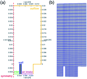 | ||
| Fig. 1 Computational geometry of the numerical model with dimensions and annotated boundaries (a) and the mesh used for discretization of the partial differential equations (b). | ||
There is a different boundary condition imposed for each boundary. For the inlet boundary, we prescribe the mean velocity of the flow, calculated from the flow rate and tube diameter. We also impose the Dirichlet boundary condition for the mass fractions of all the species – in the default case without impurities, all mass fractions are set to zero, except for argon and hydrogen.
For the wall boundary, we prescribe a zero-gradient boundary condition for the species' number densities and a no-slip boundary condition for mixture velocity. By assuming zero-gradient at the walls, we effectively neglect quenching of reactive species by surface reactions. This is a reasonable assumption because the area of the wall which is in contact with the flame is small.
The air intake boundary condition serves as a source of fresh air (oxidizer) in the model. Therefore, we set the mass fractions of all the species except for O2, N2 and H2O to zero. Regarding velocity, we impose a constant flow velocity of 0.05 m s−1 on the air intake, to provide a steady supply of air. In the experimental system, there is no forced flow outside the MDF tube, but the air circulates around it due to the buoyancy force. It is, however, not practical to assume a zero-gradient boundary condition for velocity on the intake because the system of equations would not have a unique solution.
Finally, the outflow boundary condition assumes a zero-gradient for both the species mole fractions and for the gas mixture velocity, acting as a free outflow for both these quantities.
2.4 Model distribution
As mentioned in the Introduction, the model described in this work is provided to the community in the form of configuration files that can be executed using the laminarSMOKE solver. The model files are provided as the ESI† and also in a public git repository located at: https://bitbucket.org/adamobrusnik/mdf-atomizer-laminarsmoke.3 Experimental
The model was benchmarked against the MDF atomizer. The simple design of this device reduces the number of experimental uncertainties and imperfections.Unlike many studies focusing on combustion simulation, which chooses the simulated and experimental flame radius or length and flame velocities as the main observable,19–21 this work goes into greater detail by using the H radical 2D maps as the observable. The rationale behind this is that the distribution of H radicals has a determining influence on an atomizer's performance, as detailed in the Introduction.
3.1 Miniature diffusion flame atomizer
The MDF atomizer described e.g. in ref. 22 is a simple device consisting of a quartz glass tube (quartz, inner diameter 6 mm, outer diameter 8.5 mm), through which a mixture of hydrogen (99.95%, SIAD Ltd., Czech Republic) and argon (99.996%, SIAD Ltd., Czech Republic) was fed to ambient air. The flame was ignited at the end of the tube, where the hydrogen/argon mixture mixes with ambient air. The gas flow rates were controlled by using mass flow controllers (FMA 2400 Series, Omega Engineering, Inc., USA). The gases were pre-mixed before entering the quartz tube.3.2 Laser-induced fluorescence measurement
In order to measure the distribution and concentration of hydrogen radicals,23,24 they were excited by 8 ns long laser pulses with a wavelength of 205 nm and a spectral width of 0.06 cm−1. The laser pulses were produced with a 30 Hz repetition rate by using a laser system consisting of a Q-switched pumping laser (Quanta-Ray PRO-270-30), a dye laser (Sirah, PRSC-D-24-EG) and a frequency tripling unit. Laser radiation was focused on the center of the studied atomizer by using a spherical silica lens (focal length approx. 50 cm). The energy of each pulse (typically hundreds of μJ) was detected by using a pyroelectric energy sensor (Ophir PE9). The hydrogen fluorescence (Hα, 656 nm) was recorded by using an intensified CCD camera (PI-MAX 1024RB-25-FG43) with an interference filter. The integration time of the ICCD was 10 s in all the experiments.In order to obtain the absolute concentration of atomic hydrogen, the sensitivity of the detection was calibrated by measurement of Kr TALIF.25,26 Kr atoms with a known concentration (1.5–8%) in Ar gas were excited by using a laser with a wavelength of 204 nm and the generated Kr fluorescence was detected. Then, the atomic hydrogen concentration was calculated by means of the formula
| NH = NKr(SH/SKr)(EKr/EH)2(νH/νKr)2(σ(2)Kr/σ(2)H)(qKr/qH)(KKr/KH), |
4 Results and discussion
4.1 Species' spatial distribution
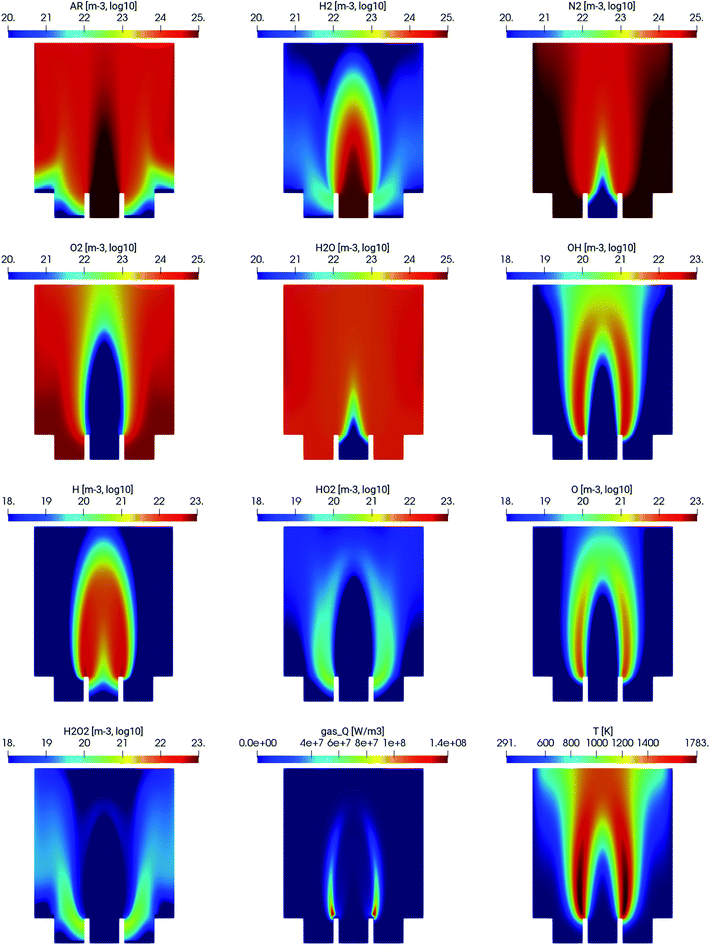
The spatial distribution of the different species in the MDF atomizer is shown in Fig. 2. As expected, the combustion of hydrogen and oxygen occurs in the interfacial region, where the argon/hydrogen mixture mixes with ambient air. This is illustrated especially by the subplots gas_Q, showing the heat released by combustion and T being the gas temperature. As expected, the most reactive H and OH species are also present only in the combustion region.4.2 Experimental validation
We benchmarked the model against the spatially resolved density of H radicals measured by TALIF. It is a good measure of the flame's properties because H radicals will only be present in the active combustion zone. Most importantly, according to the radical theory of hydride atomization the distribution of H radicals controls what happens in atomizers (see Introduction). Two types of data sets have been obtained experimentally – a 1D radially resolved measurement of the H radical number density which has been absolutely calibrated and 2D spatially resolved maps of H radicals. With the 2D data, the quantum yield of the H fluorescence could not have been measured with sufficient accuracy, so we only plot the data in arbitrary units.The 1D radially resolved data allow us to quantitatively compare the model predictions with the experiment. The data are plotted in Fig. 3 for 2 mm above the top of the atomizer tube. It is apparent that, in terms of absolute values, the number density of H is within the same range. The experimental data are, however, more diffuse compared to the simulation data. This is most likely caused by the jittering of the flame, which effectively changes the position over the 10 s integration time of the ICCD camera.
 | ||
| Fig. 3 Spatial distribution of H radicals along a horizontal line, 2 mm above the top of the quartz tube. | ||
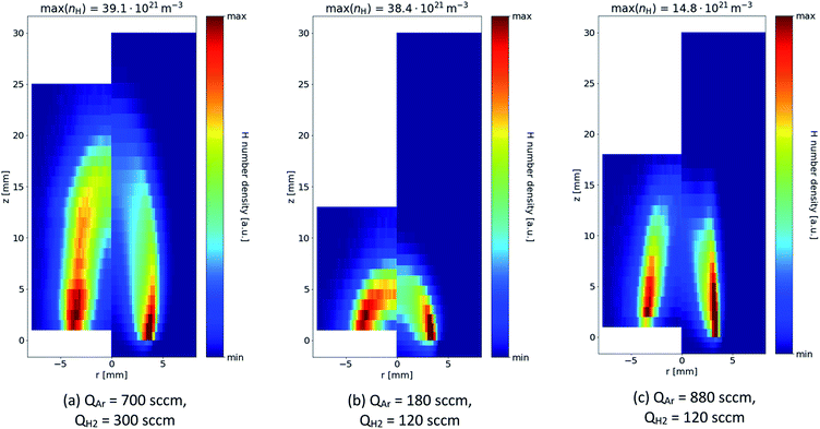
The more diffuse nature of the experimentally measured data is also apparent in the 2D spatially resolved data, shown in Fig. 4. However, the model tends to capture very accurately the length of the flame and the overall shape of the H-rich regions in several ratios of argon/hydrogen supplied to the atomizer. Apparently, H radicals are present especially in the interfacial mixing region, where the argon/hydrogen mixture supplied to the atomizer mixes with ambient air.
The model and experiment consistently show that the length of the flame can be controlled by the argon flow rate – compare Fig. 4(b) and (c). This is because increasing the argon flow rate effectively increases the flow velocity and the combustion of hydrogen occurs over a greater distance. At the same time, however, increasing the argon flow rate decreases the absolute density of H radicals. On the other hand, increasing the fraction of H2 (under the same flow rate of the Ar/H2 mixture) does increase the flame length and H radical density – compare Fig. 4(a) and (c).
4.3 Sensitivity to experimental uncertainties
To model an actual experimental setup, one must take into account all the manufacturing and experimental uncertainties that could influence the simulation results. In this section, we quantify how these uncertainties influence the simulation result. We have chosen QAr = 700 sccm and QH2 = 300 sccm as the default working point with a laboratory air humidity of 40% at 300 K and 0 ppm air admixture in the atomizer. In accord with the dimensions of the MDF, the inner diameter of the quartz tube was set to 6 mm. However, in various reproductions of the experiment, these values might not always be maintained. Therefore, we have carried out a series of simulations to assess the sensitivity of the model to the key parameters. These simulations are summarized in Table 1. The variations to the model parameters correspond to actual instrument or manufacturing tolerances.| Simulation label | Description |
|---|---|
| Dry air | Humidity of laboratory air set to 0% |
| Humid air | Humidity of laboratory air set to 100% |
| Smaller tube | Tube i.d. decreased to 5.6 mm |
| Larger tube | Tube i.d. increased to 6.4 mm |
| Impurity 0.1% | 0.1 molar% of air added to the gas inlet |
Two observables were chosen for quantifying the uncertainty. One is the absolute yield of H radicals produced by the atomizer  – i.e. the number density of hydrogen radicals integrated over the simulation domain. The second observable is the length of the flame Lf which is defined as the position on the z-axis, where the mass fraction of H2 drops below 0.1% of the maximum value. In both cases, we plot the change in these observables with respect to the default simulation – the value of ΔLf = +10% corresponds to a 10% increase of the flame length w.r.t the default simulation.
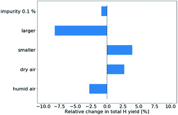
Firstly, in Fig. 5, we plot the sensitivity of the total hydrogen yield. Apparently, the main sources of uncertainty in the presented setup are the tube diameter. Having a tube with a diameter increased by 0.4 mm reduces the total H yield by approximately 10% while decreasing the tube diameter increases the H yield by approximately 6%. The humidity of ambient air plays only a small role in the total H yield, with the H yield decreasing with increasing humidity. This result is reasonable, considering that H2O molecules will deplete some of the H radicals, ultimately converting them to H2O2. Finally, the 0.1% air impurity in the gas inlet has only minor impact on the total H yield.
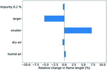
In Fig. 6, we plot the sensitivity of the simulated flame length to experimental uncertainties. In this case, only the tube diameter has non-negligible influence within the range of experimental uncertainties specified in Table 1. The result is to be expected as a larger tube diameter decreases the initial velocity of the gas flow while a smaller diameter increases it, thereby stretching the flame longer.
5 Conclusions
In this publication, we have introduced an open-source computational model of non-premixed hydrogen combustion in atomizers. The model is based on an open-source (for academic use) solver laminarSMOKE and the reaction mechanism used is a sub-set of the GRI-Mech 3.0 reaction mechanism.The model developed has been used for simulating H radical production in a simple MDF atomizer. By comparing the simulated H density profile with TALIF measurements of the same quantity, we confirmed that the predictions of the model are correct, both in terms of the shape of the flame and in terms of the absolute values of H radical concentrations. The main difference between the simulation and the experimental data lies in the fact that the experiment shows H density profiles which are more diffuse. However, this observation may be attributed both to the imperfections of the model (underestimated diffusion) and experimental imperfections (moving or oscillatory flame position).
We have also used the model to assess the sensitivity of the MDF atomizer to uncertain laboratory conditions and geometrical parameters. The ability to quantify how laboratory conditions and other experimental parameters influence the performance of an atomizer is another example of how the computational model can be utilized.
Since the H radical distribution controls what happens in atomizers, it has become obvious that the presented model is a powerful predictive tool that can be utilized for the design and optimization of not only MDF atomizers but other atomizer configurations as well. The model supports both 2D axially symmetrical setups, e.g. flames in gas shield atomizers, and setups which require full 3D geometry, e.g. conventional externally heated quartz tube atomizers or multiatomizers.3
By providing the model simulation files under an open-source license, we allow and invite other members of the analytical chemistry community to modify the geometry or operating conditions and use the tool for their research.
Conflicts of interest
There are no conflicts to declare.Acknowledgements
This research has been supported by the Czech Science Foundation under contract 17-04329S, by the Czech Academy of Sciences, Institute of Analytical Chemistry (Institutional Research Planno. RVO: 68081715). This research has been supported by project CEPLANT (LM2018097) funded by the Ministry of Education, Youth and Sports of the Czech Republic.References
- S. Becker, Inorganic Mass Spectrometry: Principles and Applications, Wiley, 2008 Search PubMed.
- A. D'Ulivo, AF detectors, in Environmental Analysis Using Chromatography Interfaced with Atomic Spectroscopy, ed. R. M. Harrison and S. Rapsomanikis, Ellis Horwood, Chichester, 1989, pp. 127–164 Search PubMed.
- J. Dědina, A. D'Ulivo, L. Lampugnani, T. Matoušek and R. Zamboni, Selenium hydride atomization, fate of free atoms and spectroscopic temperature in miniature diffusion flame atomizer studied by atomic absorption spectrometry, Spectrochim. Acta, Part B, 1998, 53(13), 1777–1790 CrossRef.
- J. Dědina, Atomization of volatile compounds for atomic absorption and atomic fluorescence spectrometry: on the way towards the ideal atomizer, Spectrochim. Acta, Part B, 2007, 62(9), 846–872 CrossRef.
- M. Ezer and J. B. Simeonsson, Determination of trace tin by continuous flow hydride generation laser induced fluorescence spectrometry, Fresenius Environ. Bull., 2009, 18(9), 1572–1577 CAS.
- P. Wu, X. Wen, L. He, Y. He, M. Chen and X. Hou, Evaluation of tungsten coil electrothermal vaporization-Ar/H2 flame atomic fluorescence spectrometry for determination of eight traditional hydride-forming elements and cadmium without chemical vapor generation, Talanta, 2008, 74(4), 505–511 CrossRef CAS PubMed.
- E. Pitzalis, D. Ajala, M. Onor, R. Zamboni and A. D'Ulivo, Chemical vapor generation of arsane in the presence of L-cysteine. Mechanistic studies and their analytical feedback, Anal. Chem., 2007, 79(16), 6324–6333 CrossRef CAS PubMed.
- M. Murillo, N. Carrión, J. Colmenares, J. Romero, G. Alvarado and M. Ríos, et al., Design and evaluation of a continuous flow, integrated nebulizer-hydride generator for flame atomic absorption spectrometry, Quim. Nova, 2008, 31(6), 1315–1318 CrossRef CAS.
- J. Dědina and I. Rubeška, Hydride atomization in a cool hydrogen-oxygen flame burning in a quartz tube atomizer, Spectrochim. Acta, Part B, 1980, 35(3), 119–128 CrossRef.
- B. Welz and M. Melcher, Mutual interactions of elements in the hydride technique in atomic absorption spectrometry. Part 1. Influence of selenium on arsenic determination, Anal. Chim. Acta, 1981, 131(C), 17–25 CrossRef CAS.
- J. Dědina, D. L. Tsalev, Chemical Analysis: A Series of Monographs on Analytical Chemistry and Its Applications, Hydride Generation Atomic Absorption Spectrometry, Wiley, 1995, available from https://books.google.cz/books?id=6wDKAQAACAAJ Search PubMed.
- P. Dvořák, M. Talába, J. Kratzer and J. Dědina, Radical theory of hydride atomization confirmed after four decades-determination of H radicals in a quartz hydride atomizer by two-photon absorption laser-induced fluorescence, Chem. Sci., 2019, 10(12), 3643–3648 RSC.
- G. P. Smith, D. M. Golden, F. Michael, N. W. Moriarty, B. Eiteneer, M. Goldenberg, et al., GRI-MECH 3.0 [Internet]. Online, 2019, available from http://combustion.berkeley.edu/gri-mech Search PubMed.
- V. V. Toro, A. V. Mokhov, H. B. Levinsky and M. D. Smooke, Combined experimental and computational study of laminar, axisymmetric hydrogen-air diffusion flames, Proc. Combust. Inst., 2005, 30(1), 485–492 CrossRef.
- A. Cuoci, A. Frassoldati, T. Faravelli and E. Ranzi, Numerical modeling of laminar flames with detailed kinetics based on the operator-splitting method, Energy Fuels, 2013, 27(12), 7730–7753 CrossRef CAS.
- P. Welahettige, K. Vaagsaether. Comparison of OpenFOAM and ANSYS Fluent. Proc 9th EUROSIM Congr Model Simulation, EUROSIM 2016, 57th SIMS Conf Simul Model SIMS 2016, 2018, vol. 142, pp. 1005–1012 Search PubMed.
- E. L. Cussler, Diffusion: Mass Transfer in Fluid Systems, Engineering. Cambridge: Cambridge University Press, 3rd edn, 2009, vol. 2, p. 580 Search PubMed.
- A. Cuoci, A. Frassoldati, T. Faravelli and E. Ranzi, OpenSMOKE++: An object-oriented framework for the numerical modeling of reactive systems with detailed kinetic mechanisms, Comput. Phys. Commun., 2015, 192, 237–264, DOI:10.1016/j.cpc.2015.02.014.
- E. R. Hawkes and J. H. Chen, Direct numerical simulation of hydrogen-enriched lean premixed methane-air flames, Combust. Flame, 2004, 138(3), 242–258 CrossRef CAS.
- S. Bougrine, S. Richard, A. Nicolle and D. Veynante, Numerical study of laminar flame properties of diluted methane-hydrogen-air flames at high pressure and temperature using detailed chemistry, Int. J. Hydrogen Energy, 2011, 36(18), 12035–12047 CrossRef CAS.
- M. Alliche and S. Chikh, Study of non-premixed turbulent flame of hydrogen/air downstream Co-current injector, Int. J. Hydrogen Energy, 2018, 43(6), 3577–3585, DOI:10.1016/j.ijhydene.2017.06.081.
- K. Marschner, S. Musil and J. Dědina, Flame-in-gas-shield and miniature diffusion flame hydride atomizers for atomic fluorescence spectrometry: optimization and comparison, Spectrochim. Acta, Part B, 2015, 109, 16–23 CrossRef CAS.
- J. Bokor, R. Freeman, J. White and R. Storz, Two-photon excitation of the n = 3 level in H and D atoms, Phys. Rev. A, 1981, 24(1), 2577 CrossRef.
- J. Amorim, G. Baravian, M. Touzeau and J. Jolly, Two-photon laser induced fluorescence and amplified spontaneous emission atom concentration measurements in O2 and H2 discharges, J. Appl. Phys., 1994, 76(3), 1487–1493 CrossRef CAS.
- M. G. H. Boogaarts, S. Mazouffre, G. J. Brinkman, H. W. P. Van Der Heijden, P. Vankan and J. A. M. Van Der Mullen, et al., Quantitative two-photon laser-induced fluorescence measurements of atomic hydrogen densities, temperatures, and velocities in an expanding thermal plasma, Rev. Sci. Instrum., 2002, 73(1), 73 CrossRef CAS.
- K. Niemi, V. Schulz-von Der Gathen and H. F. Döbele, Absolute calibration of atomic density measurements by laser-induced fluorescence spectroscopy with two-photon excitation, J. Phys. D: Appl. Phys., 2001, 34(15), 2330–2335 CrossRef CAS.
- M. Mrkvičková, J. Ráheľ, P. Dvořák, D. Trunec and T. Morávek, Fluorescence (TALIF) measurement of atomic hydrogen concentration in a coplanar surface dielectric barrier discharge, Plasma Sources Sci. Technol., 2016, 25(5), 055015 CrossRef.
- P. Dvorák, M. Talába, A. Obrusnik, J. Kratzer and J. Dědina, Concentration of atomic hydrogen in a dielectric barrier discharge measured by two-photon absorption fluorescence, Plasma Sources Sci. Technol., 2017, 26(8), 085002 CrossRef.
Footnote |
| † Electronic supplementary information (ESI) available: kinetic_scheme.pdf: the reaction mechanism used in this work; mdfatomizer-laminarsmoke-20200129.zip: a ZIP archive with geometry, kinetics and model configuration files for the default configuration. Includes a README file with execution instructions and all the kinetic- and thermo-chemistry input data in CHEMKIN format. See DOI: 10.1039/d0ja00099j |
| This journal is © The Royal Society of Chemistry 2020 |


