 Open Access Article
Creative Commons Attribution 3.0 Unported Licence
Making electrochemistry easily accessible to the synthetic chemist
Christiane
Schotten
*a,
Thomas P.
Nicholls
 a,
Richard A.
Bourne
 b,
Nikil
Kapur
 c,
Bao N.
Nguyen
 a and
Charlotte E.
Willans
 *a
*a
aSchool of Chemistry, University of Leeds, Leeds LS2 9JT, UK. E-mail: C.Schotten@leeds.ac.uk; C.E.Willans@leeds.ac.uk
bSchool of Chemical and Process Engineering, University of Leeds, Leeds LS2 9JT, UK
cSchool of Mechanical Engineering, University of Leeds, Leeds LS2 9JT, UK
First published on 21st May 2020
Abstract
A significantly renewed interest in synthetic electrochemistry is apparent in the increasing number of publications over the last few years. Electrochemical synthesis offers a mild, green and atom efficient route to interesting and useful molecules, thus avoiding harsh chemical oxidising and reducing agents used in traditional synthetic methods. As such, encouraging broader application of electrochemistry by synthetic chemists should be a priority. Despite the renewed interest there remains a barrier to widespread adoption of this technology derived from the extra knowledge and specialised equipment required. This has led to a knowledge gap between experienced electrochemists and those new in the field. In this tutorial we will bridge the knowledge gap by providing an easily accessible introduction which will enable synthetic chemists new to the field to explore electrochemistry. We will discuss mechanistic considerations, the setup of an electrochemical reaction with all its components, trouble shooting and selected examples from the literature.
Introduction
During the last decade, electrochemistry has received renewed interest as a tool for synthetic chemistry.1–17 This is exemplified by whole journal issues being dedicated to synthetic electrochemistry.18,19 Electrochemistry offers a very mild and atom efficient method to achieve selective oxidative or reductive transformations using electrons as reactants. It therefore avoids the use of other harsh and often toxic chemical reducing and oxidising agents.4,6,15 In addition, electrochemistry can offer new reaction pathways that are complimentary to traditional synthetic chemistry procedures and can be particularly interesting for late-stage functionalisation due to its mild and selective nature.10 Nonetheless, it is only in the last few years that the synthetic chemistry community has rediscovered this powerful tool for small scale synthetic applications.5,7 Its resurgence is in part due to the chemical community being driven towards more sustainable and greener reaction pathways.4,6,15 As electrochemistry uses electrons as reactants and a source of energy, the atom economy is usually increased. In addition, due to the highly selective nature, derivatisations such as protection/deprotection can often be avoided.Despite the many benefits of electrochemistry, the general perception, that specialised equipment and expert knowledge is required, presents a high barrier for chemists to adopting this exciting technique. Even though reading material for non-electrochemists20–22 and recently a ‘survival guide’23 are available, we feel the need for an easily accessible, modern introduction to electrochemistry to allow more researchers to explore electrochemistry for synthetic chemistry. We also discuss the benefits of continuous flow electrochemistry, for example as a way to address scale up. In addition, we have summarised possible parameter changes and the influence on the reaction performance.
This tutorial review provides an introduction to electrochemistry and is not designed to be an extensive review of all synthetic electrochemical examples. For further information recent reviews and the references therein are recommended: certain transformations including cross coupling,24–26 CH activation,27–36 asymmetric synthesis,14 heterocycle formation,37–39 arylation,40 fluorination,41 organometallic catalysis,42,43 cation pool method,44 continuous reactor types,45–55 analytical tools56,57 and general reviews and perspectives.1–17
Terminology
Power supply – electricity sourceCurrent – movement of electrons (I in ampere)
Potential – voltage difference between two electrodes, provides energy to move electrons (U in volt)
Charge – current passed over time (Q in coulomb)
Electrode – conducting material that carries current into reaction solution
Cathode – reduction electrode
Anode – oxidation electrode
Working electrode – electrode where the reaction of interest is happening (WE)
Counter electrode – electrode opposite to working electrode (CE)
Counter reaction – reaction on the counter electrode
Cyclic voltammetry – an electrochemical analytical tool (CV)
Overpotential – additional potential required, dependent on e.g. the electrode material
Standard potential – potential of a redox reaction under standard conditions
Principles of synthetic electrochemical reactions
A simple electrochemical setup is comprised of a reaction vessel with a power supply (1), a reaction solution (2) and two electrodes (3 and 4) which are connected to the power supply (Fig. 1). The reaction solution consists of a solvent, the substrate(s) and, if necessary, an electrolyte and additives. Separate electrochemical reactions will happen on both electrodes. The anode (3, red) is defined as the oxidation electrode, the cathode (4, black) as the reduction electrode. The arrows on the connections to the power supply indicate the direction of electron flow, from the anode to the cathode. Both reactions, oxidation and reduction, are coupled and one will not happen without the other. The electrode at which the reaction of interest is happening is called the working electrode, the second electrode is called the counter electrode (see section Counter reaction). The electrical circuit is completed through the movement of charged species through the reaction solution.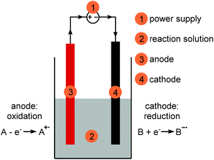 | ||
| Fig. 1 Simple electrochemical setup for synthesis purposes; red: anode, black: cathode, grey: reaction solution. | ||
Electrochemical reactions occur through single electron transfer (SET) to the substrate, usually forming radical species which can then react further to ultimately form a final product. In this respect electrochemistry is based on similar principals as photochemistry.58 However, electrochemistry is a heterogeneous process on the electrode surface which means that it can be restricted by the surface area of the electrode.
The electrons are supplied by a power supply (see section Power supply) that pushes electrons from the anode (oxidation electrode) to the cathode (reduction electrode) creating an electrochemical potential. If this potential is greater than the substrate's redox potential, a chemical reaction will happen (Fig. 2a). The flow of electrons is described by the current, which is proportional to the number of electrons transferred. The direction of the current is thereby defined as the opposite to the flow of electrons. The energy to provide the electron gradient is described by the potential. The current describes the rate of electron transfer and is therefore proportional to the stoichiometry of electrons. The potential describes how strongly oxidising and reducing the conditions are (see section Current and potential).
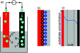 | ||
| Fig. 2 (a) Movement of electrons in an electrochemical reaction, (b) Helmholtz double layer, (c) Nernst diffusion layer; red: anode, black: cathode, grey: reaction solution. | ||
At the electrode surface an electrochemical double layer (Helmholtz layer) is formed (Fig. 2b).59 The double layer consists of two layers of charged species of opposite polarities and is formed when an electronic conductor (the electrode material) is in contact with an ionic conductor such as an electrolyte. For example, the anodic double layer consists of a positively charged layer on the electrode surface and a negatively charged layer of the solvated electrolyte that covers the electrode surface. The thickness of the double layer is mostly dependent on the applied voltage and the electrolyte concentration but is typically in a few nanometer scale. The Nernst diffusion layer describes the concentration of the substrate near the electrode (Fig. 2c). As the substrate is consumed, the concentration is lower at the electrode compared to the bulk solution resulting in further substrate diffusion towards the electrode. If the substrate is produced, rather than consumed, the concentration is increased near the electrode. So when depositing copper onto a cathode from a sacrificial copper anode, the copper concentration is low at the cathode as it is consumed. However, the copper concentration is high at the anode because it is released from the sacrificial anode. The scale of the diffusion layer is commonly under 0.1 mm.60 Analogous to a traditional heterogeneous reaction, mass transport has to be fast enough to overcome this concentration gradient to allow the reaction to continue. This can for example be achieved through fast enough stirring or narrow electrode gaps.
Counter reaction
The electrochemical reactions at both electrode surfaces are intrinsically linked. The reaction occurring on the counter electrode is called the counter reaction. The electrons removed at the anode are driven to the cathode by the power supply ensuring a net neutral system. It is important to consider the counter reaction when optimising an electrochemical reaction, as it can be the rate limiting factor in a process. For example, the oxygen evolution in electrochemical water splitting is the rate limiting step, so the substitution to a faster reaction can boost the evolution of hydrogen. In this manner, the oxidation of amines to nitriles as a counter reaction to the reduction of water for hydrogen production has been investigated.61A counter reaction in synthetic chemistry occurring at the cathode is commonly solvent degradation, often deprotonation resulting in hydrogen formation.35,36 It can be promoted, for example, by adding a proton donor such as an acid into the system.
A typical counter reaction at the anode is also solvent degradation or the oxidation of a sacrificial metal anode (see section Electrodes) may be used. In addition, sacrificial additives similar to the acid for a cathodic counter reaction can be added when the initial counter reaction is not efficient enough.61
Current and potential
The most important parameters for an electrochemical reaction are the current (I) and the potential (U). The current describes the movement of electrons, the potential describes the energy by which they are moved. The current controls the rate of electrons transferred into the reaction medium and hence the reaction rate. The charge (Q) is the current per unit time and relates to the total number of electrons released into the reaction medium, analogous to a reagent stoichiometry. The energy of the electrons, the potential, needs to be adjusted to the potential of the desired process. Most synthetic reactions occur at potentials up to 2 V. If the potential is too low, the reaction will not happen, and if it is too high then selectivity issues might arise. The current and potential are related by the resistance (R) in a process. This resistance is an adduct of various components of the process, such as the wiring and the electrodes, but by far the biggest contributors are the reaction solution and the reaction itself. All three parameters, the potential, resistance and current, are linked and one cannot be changed without the other.| U = R·I |
Reactions can be run under constant current, termed galvanostatic, or constant potential, termed potentiostatic conditions. It is not possible to control both the current and the potential separately without changing the resistance of the setup, which is challenging practically. Both sets of conditions have advantages and disadvantages which will be further discussed in the next sections (for a summary see Table 1).
| Galvanostatic (constant current) | Potentiostatic (constant potential) |
|---|---|
| + Easy setup | − Only reproducible with reference electrode |
| + Exact equivalents of electrons known (F mol−1) | − Equivalents of electrons not directly controlled |
| − Voltage range not controlled | + Ability to adjust the process potential to improve selectivity |
| Q = I·t |
| Q = n·N·F |
![[thin space (1/6-em)]](https://www.rsc.org/images/entities/char_2009.gif) 485 s A mol−1].
485 s A mol−1].
For a specific current the time for the required charge to pass into the reaction can be calculated.
The time calculated is the time required for one electron equivalent, (equiv., often referred to as 1 F or 1 F mol−1), and can be extended to achieve higher electron equivalents.
The Faradaic efficiency (n), or current efficiency, describes how many of the electrons transferred into the reaction mixture end up in the product. Equivalents of electrons and the yield are taken into account. This is an effective way to compare reactions with different electron equivalents. Faradaic efficiency is calculated from the theoretical charge (Qtheo) and the experimental charge (Qexp). Qtheo describes the charge theoretically required to obtain the amount of observed product, in other words how many electrons ended up in the product, taking the yield into account. The experimental charge (Qexp) describes the total charge transferred into the reaction mixture during the experiment, taking the equivalents of electrons used (F mol−1 or equiv.) into account.
| Qtheo = zP·NP·F = z·N·Y·F |
| Qexp = I·t = z·N·F·equiv. |
n: Faradaic efficiency in percent [%], Qtheo: theoretical charge in Coulomb [C], Qexp: experimental charge in Coulomb [C], equiv.: electron equivalents, zP: Number of electrons per product [−], NP: Number of mols of the product [mol],Y: yield in percent [%].
The potential is not actively controlled under galvanostatic conditions and, depending on the resistance of the process, will vary to maintain constant current. A high potential means that there is a high resistance between the two electrodes. The resistance and therefore the potential can be decreased by moving the electrodes closer together, adding more electrolyte (see section Electrolytes) or by increasing the electrode surface area. The current density, current per electrode surface area, allows direct comparison between different experimental setups as it standardises the current for the electrode surface area used. Generally, a low current density results in milder reaction conditions due to a decreased potential, which might avoid issues with selectivity and electrode stability. Lowering the current (and increasing the reaction time) will also result in a decreased potential. At high potentials the reaction conditions are more aggressive and undesired reactions may occur. As the current is proportional to the rate of the reaction, a lower current will result in a longer reaction time needed to pass the total charge desired, in addition to lowering the potential. Hence a trade-off between low potential (mild conditions) and reaction time exists. In addition, the effect of a high current heating up the reaction mixture, called joule or ohmic heating, might lead to changes in reaction temperature over time and active cooling could be considered.
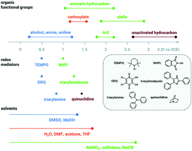 | ||
| Fig. 3 Oxidation potentials for organic functional groups, redox mediators and solvents, adapted from ref. 66 with permission from The Royal Society of Chemistry. | ||
Ordinarily, a higher potential than the standard potential has to be applied for the desired reaction to occur. The difference is derived from reactions typically not being performed under standard conditions and an additional potential to overcome kinetic inhibition, called the overpotential.
As most electrochemical reactions are not performed under standard conditions, it is important to recognise that the concentration has an effect on the redox potential. For a reversible reaction, this relationship is described in the Nernst equation. It assumes that, at a certain potential, both species of the redox couple are in equilibrium.
| Ox + e− → Red |
At 25 °C this can then be written as:
Thus, the potential changes as the reaction progresses to a new equilibrium. Assuming a one electron reduction starts under standard condition, at 99% conversion the equilibrium potential which needs to be overcome can be calculated as:
An increase of 0.12 V should be expected in the applied potential to maintain the reaction progress.
The overpotential is dependent on the electrochemical reaction and the electrode material. For hydrogen evolution at typical electrode materials, carbon materials have the highest hydrogen overpotential (∼−0.6 V), most metal electrodes have a medium overpotential (e.g. Fe, Ag, Ni, ∼−0.2 V) and platinum, palladium and gold have the lowest (∼−0.1 V). The investigation of other electrode materials for hydrogen production, such as metal oxide composites, is an active area of research.64
When looking at an electrochemical process, both the oxidation and reduction must be considered as the overall potential of the redox system derives from the combination of both cell potentials. For example, if the oxidation requires a potential of 1 V and the reduction requires a potential of 2 V, then the cell potential will be 3 V.
If a potentiostatic reaction is conducted without a reference electrode, the reaction setup must be reproducible. This is only possible by fully describing the setup, particularly in terms of electrolyte concentration and electrode distance/ arrangement. Nonetheless, such a reaction is likely to suffer from difficulties with respect to reproducibility in a different reaction setup. Reproducing a galvanostatic reaction in a different reaction setup typically has a higher possibility of success. Therefore, a full description of reaction conditions including the reaction setup should be disclosed.
Cyclic voltammetry as an analytical tool
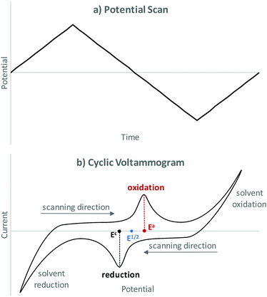
Cyclic voltammetry (CV) is an analytical tool that is used to determine redox potentials for electrochemical transformations. A well explained guide to CV specifically for synthetic chemists has been prepared by Dempsey and co-workers.56 A CV setup comprises of a CV working and counter electrode and a reference electrode. Note that, the working electrode is different than that used in synthetic purposes. During a CV experiment the current is measured while the potential at the working electrode is scanned in a cyclic manner using a triangular waveform (see Fig. 4a) resulting in a cyclic voltammogram (see Fig. 4b). If the potential is increased and there is no reaction happening, no increase in current is observed. If a species is present that can be oxidised or reduced under the voltage applied, a current will flow until the species is depleted at the electrode surface resulting in a peak. Depending on the potential window scanned, solvent oxidation and/or reduction might also be observed. The potential at which the maximum current is observed is referred to Ea and Ec for anodic and cathodic respectively. The middle of these two potentials is then the redox potential of the chemical transformation within this system (E1/2). CV helps to understand a redox system and the potential required for a redox event to occur. In this respect, CV can aid in the elucidation of reaction mechanisms.Measured potentials are dependent on the type of reference electrode used and will vary significantly when using a different reference electrode (see section Reference electrode). A typical strategy to allow comparison between different systems is to introduce an additional, well-known redox system such as the ferrocene/ferrocenium (Fc/Fc+) redox couple. These systems are utilised as internal standards and then referenced to a reference electrode potential.65 When recording a cyclic voltammogram, it is important to realise that the first cycle often looks different to repeated cycles. This can be due to passive layers on the electrodes being removed, or deposit on the electrode during a cycle. Therefore, several cycles should be recorded and evaluated. As a starting point a potential where no current is flowing should be chosen. Dependent on the system, the potential scan rate can have a significant effect on the cyclic voltammogram. However, some processes might not be fully reversible so that the reverse peak can be smaller or even disappear completely making the two peaks unsymmetrical. As this is dependent upon the time-scale of the reaction, a faster scan rate can often exhibit semi-reversible processes more clearly.
Setup of an electrochemical reaction
Power supply unit (PSU)
The power supply drives the reaction forwards by supplying the electricity to the system and moving electrons from the anode to the cathode. In a way, the power supply acts as the pump of electrons in the system. In the simplest case batteries can be used, however the output voltage and current cannot be controlled easily without extra electronic equipment.Potentiostats and bench-top power supplies can control either the current or the voltage so that the reaction input can be tailored to the desired conditions (see section Current and potential). Potentiostats generally have further functionality in addition to constant voltage or current and can therefore also be used for electrochemical analytical methods (see section Cyclic voltammetry as an analytical tool). Potentiostats also allow the use of a reference electrode which enables the potential at the working electrode to be controlled precisely. For electrochemical syntheses without using a reference electrode, a bench-top power supply is often sufficient and adequate equipment can be purchased for under £100 (e.g. Tenma 72-10480). Possible alterations include a multichannel power supply or an RS232 adapter for connection to a computer.
Electrodes
Generally, any conducting material can be used as an electrode. However, depending on the electrode material, size and shape, significant differences in reaction outcome can be observed. As the reactions happen on the electrode surface, the surface area is a significant factor. Foams or meshes have a higher surface area than plates or rods and can therefore be beneficial for a reaction by increasing the reaction rate. As the oxidation and reduction reactions are coupled, both electrode surfaces are important.Parameters to consider when selecting electrode material are: chemical and electrochemical inertness, promotion of counter reaction and price and availability (see summary in Table 2).
| Material | Inertness | Counter reaction | Comments | |
|---|---|---|---|---|
| Electrode performance ranked in ✓: good, ▲: medium, ✗: bad. | ||||
| Pt | Anode | ✓ | ✓ | Expensive |
| Cathode | ✓ | ▲ | Competition through hydrogen evolution possible | |
| Graphite | Anode | ✓ | ▲ | Porous material, cleaning routine important |
| Cathode | ✓ | ▲ | ||
| Glassy carbon | Anode | ✓ | ▲ | Similar to graphite but non-porous |
| Cathode | ✓ | ▲ | ||
| Reticulated vitreous carbon (RVC) | Anode | ✓ | ▲ | Similar to graphite but very high surface area |
| Cathode | ✓ | ▲ | ||
| Stainless steel (SS) and Fe | Anode | ✗ | ▲ | Inexpensive, not suitable as anode, can get rusty |
| Cathode | ✓ | ▲ | ||
| Zn, Cu, Ni and other metals | Anode | ✗ | ✓ | Suitable as sacrificial anode |
| Cathode | ✓ | ▲ | ||
Batch reactor vessels
Different setups of the reactor vessel, often referred to as the electrochemical cell, are possible (Fig. 5a). In the simplest case both electrodes are fitted into the same compartment of the vessel, the reaction chamber, and share the reaction solution. This is called an undivided electrochemical cell. This setup can be used if the reaction product is stable under the electrochemical conditions (i.e. is not decomposed on the counter electrode) and is compatible with the counter reaction. Vessels such as beakers or round-bottom flasks have been used (Fig. 5b).67,68 However, in these cases the electrodes inevitably will be positioned slightly differently in each setup, with different angles and distances between electrodes which can have an effect on the reaction outcome. Therefore, effort has been made to develop more standardised reaction vessels. Most of these are built in-house with electrodes being fixed in position with seals72–75 though more sophisticated solutions including systems for rapid screening have been established.69,70,76,77 Access to these reaction setups is often problematic as in-house engineering capacity is necessary. In addition, commercially available equipment has been made available over the last few years (Fig. 5c).78–80 For reactions where the desired and counter reactions are incompatible or the product is not electrochemically stable on the counter electrode, a divided cell should be used. In this case, the reaction chamber is divided into a cathodic and anodic reaction chamber by a membrane or a frit. It is important that the division allows charge transfer, thus ion exchange membranes are often used. Reactors made in-house have been reported81 but also commercial reactors consisting of two vessels connected by a bridge, often described as H-cells, are available.78,82,83 For potentiostatic experiments (see section Current and potential) a reference electrode must be used. The reference electrode needs to be fitted close to the working electrode.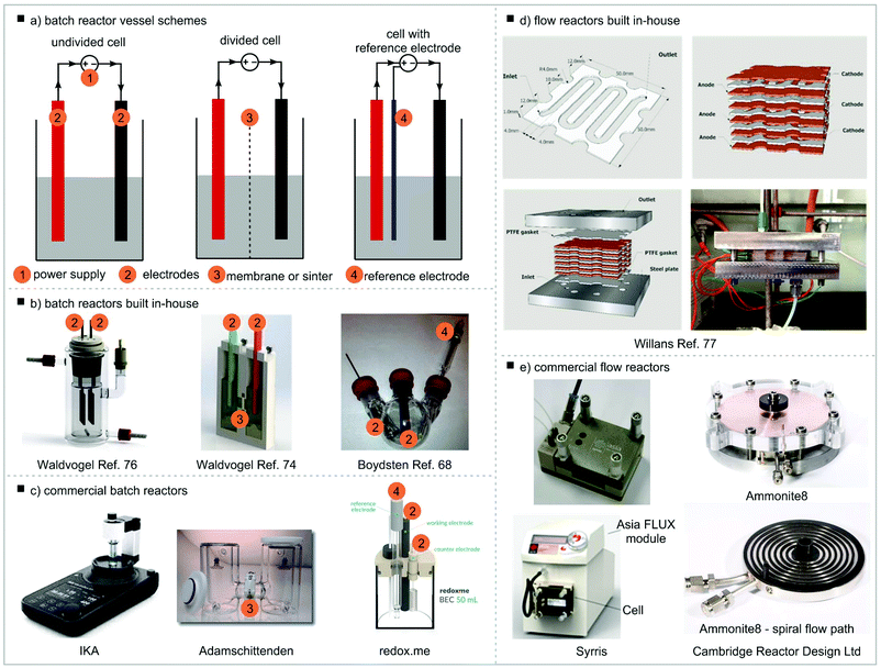 | ||
| Fig. 5 Electrochemical reactor vessels, (a) batch reactor vessel schemes, (b) batch reactors built in-house, (c) commercial batch reactors, (d) flow reactors built in-house, (e) commercial flow reactors. Undivided cell example: reproduced from ref. 69 with permission from The Royal Society of Chemistry; divided cell example: reprinted with permission from ref. 70 Copyright (2016) American Chemical Society; cell with reference electrode: reprinted with permission from ref. 68 Copyright (2012) American Chemical Society. Willans flow reactor: adapted from ref. 71 with permission from The Royal Society of Chemistry. | ||
Continuous reactor vessels
In addition to batch vessels, continuous flow electrochemical reactors have been developed (Fig. 5d).49–51,84 Usually, the two electrodes are separated by a thin spacer that has flow channels cut into it. This allows for a large electrode surface area and a small inter-electrode gap. In general, the large surface area to volume ratio that is enabled by continuous flow reactors provides advantages with respect to heat dissipation as well as energy and mass transfer. As electrochemical reactions are heterogeneous, the larger surface area to volume ratio increases energy transfer from the electrode to the solution as well as mass transfer at the solid/liquid interface. Both these effects provide an increase in the reaction rate. If the reaction is being run under galvanostatic conditions, this will result in lower potentials which allows milder and more selective reaction conditions. If the reaction is being run under potentiostatic conditions, this will result in a higher current which will increase the rate of reaction. Due to the electrodes intrinsically fixed in place by a spacer, reproducibility is usually very high in continuous flow electrochemical reactors. The interelectrode gap (typically below 2 mm) results in a low overall resistance and in the extreme, even overlapping Nernst diffusion layers where the intermediates themselves can act as the electrolyte. This enhances mass transport and allows reactions to be performed without or with very little additional electrolyte, reducing waste streams and simplifying purification. Another advantage of continuous flow electrochemical reactors is the generation of a homogeneous electric field. While electrochemical batch reactors produce an almost homogeneous electric field between the electrodes, this is not true for the majority of the reaction solution which is not located between the electrodes. Conversely, continuous flow electrochemical reactors generate a homogeneous electric field throughout the entire solution as it is entirely situated between the electrodes. Several groups have developed their own continuous flow reactors71,85–99 with commercial reactors also being available (Fig. 5e).100–105Brown and co-workers have developed an adjusted equation to calculate the current needed for an electrochemical reaction to suit typical flow parameters (see section Current and potential).106 Customarily, the concentration I and the flow rate (![[V with combining dot above]](https://www.rsc.org/images/entities/i_char_0056_0307.gif) ) are parameters controlled in continuous systems.
) are parameters controlled in continuous systems.
I = z·F·c·![[V with combining dot above]](https://www.rsc.org/images/entities/i_char_0056_0307.gif) |
![[V with combining dot above]](https://www.rsc.org/images/entities/i_char_0056_0307.gif) : flow rate in millilitre per second [mL s−1], c: concentration in mol per millilitre [mol mL−1].
: flow rate in millilitre per second [mL s−1], c: concentration in mol per millilitre [mol mL−1].
Generally, electrochemistry benefits from the use of continuous reactors in terms of reaction control (selectivity, yield) but also offers the prospect for direct scale up. We have recently highlighted challenges and benefits in the development of continuous electrochemistry protocols.107 In addition, Cantillo and co-workers published a guide to translating batch electrochemistry into single-pass continuous flow conditions.108 Continuous electrochemical cells are often used to recirculate batch solutions, however a single-pass layout offers the prospect of telescoping reaction solutions into subsequent reaction or purification steps. The authors also discussed the advantages and disadvantages of potentiostatic vs. galvanostatic conditions and the effects of interelectrode gap, electrolyte concentration, reaction pressure and steady state on the reaction outcome using the example of 4-methylanisole oxidation.
Within our group a flow reactor that uses a 1 mm PTFE spacer with a flow channel cut in to separate the electrodes has been developed (Fig. 5d). The spacers and electrodes can be stacked to achieve the desired reactor volume and are then held together by two stainless steel plates that are screwed together.71 This modular design allows a flexible layout for various applications as the reactor volume and electrode material can easily be varied. In addition, this setup enables straightforward access for cleaning.
Solvent
Similar to a traditional chemical reaction, the solvent used can have a crucial effect on the outcome of an electrochemical reaction.109 In addition to traditional rationale, such as intermediate stabilisation and reagent solubility, the following factors should be considered: solvent window, promotion of counter reaction, stabilisation of intermediates and inherent resistance (conductivity). Typical aprotic solvents are: THF, DCM, MeCN, DMF, DMA and DMSO. Typical protic solvents are (fluorinated) alcohols, such as hexafluoroisopropanol (HFIP), trifluoroethanol (TFE), MeOH and EtOH. Fluorinated alcohols, even as additives to another solvent, can significantly benefit the stability of radicals and so benefit electrochemical reactions.110 Commonly, polar solvents are used in electrochemistry as they typically exhibit a lower resistance, so a higher conductivity, than non-polar solvents and usually better dissolve the electrolytes. The use of dry and degassed solvents has to be considered if oxygen reduction or water electrolysis can pose a problem.The potential range in which the solvent is stable towards oxidation and reduction is called the solvent window (see section Cyclic voltammetry as an analytical tool to determine solvent window experimentally). The solvent window is dependent on the electrode material, electrolyte species and concentration in addition to other factors (see Table 3). The solvent must be stable under the electrochemical conditions employed. If the solvent degrades under the reaction conditions, this can become the primary reaction due to the significantly higher concentration of the solvent compared to the substrate, leading to very little conversion of the substrate itself. However, when the reaction is run within the window, a solvent with a low degradation potential can be used. For example, a solvent that degrades at 1.5 V can be used for a reaction performed at 1.0 V. When performing an oxidation reaction only the oxidative degradation of the solvent is important as it would otherwise compete. The reductive solvent degradation can be a suitable counter reaction. In many cases protic solvents can be a good oxidation solvent as they serve as a proton source, which can be reduced to hydrogen on the counter electrode. In addition, other proton sources such as acids can be added to promote the counter reaction even further (see section Additives).
| Solvent | Electrolyte | Electrode | Cathodic limit (V) | Anodic limit (V) | Window (V) |
|---|---|---|---|---|---|
| Values referenced to SCE (saturated calomel electrode), taken from the following ref. 110–113. | |||||
| H2O | 0.1 M KCl | C | −1.3 | +1.1 | 2.4 |
| 1 M KCl | Hg | −1.7 | 0 | 1.7 | |
| TBA ClO4 | Hg | −2.0 | |||
| HClO4 | Pt | +1.5 | |||
| MeCN | 0.1 M TBA BF4 | Pt | −3.1 | +3.2 | 6.3 |
| LiClO4 | Pt | −3.5 | +2.4 | 5.8 | |
| DMF | 0.1 M TBA ClO4 | Pt | −2.2 | +1.7 | 3.9 |
| Pyridine | LiClO4 | Hg | −1.7 | ||
| LiClO4 | C | +1.4 | |||
| DMSO | 0.01 M TBA PF6 | Pt | −1.0 | +1.0 | 2 |
| THF | LiClO4 | Pt | −3.6 | +1.8 | 5.4 |
| DCM | 0.1 M TBA ClO4 | Au | −1.5 | +2.0 | 3.5 |
| TBA ClO4 | Pt | −1.7 | +1.8 | 3.5 | |
| HFIP | 0.1 M TBA ClO4 | Pt | +0.8 | +2.9 | 2.1 |
| 0.1 M TBA ClO4 | C | −1.6 | +3.1 | 4.7 | |
| 0.1 M RbF | C | −1.1 | +3.4 | 4.5 | |
| MeOH | LiClO4 | Pt | −1.0 | +1.3 | 2.3 |
| MeCOOH | TEA ClO4 | Hg | −1.7 | ||
| NaOAc | Pt | +2.0 | |||
Practically, the applied overall potential can be bigger than the solvent window as the setup resistance needs to be overcome. In that case, the substrate still has to have a lower potential than the solvent degradation, but the substrate will be consumed first.
Electrolytes
An electrolyte is added to most electrochemical reactions to decrease the resistance and lower the potential in the system. How much the resistance is lowered is mostly dependent on the concentration of the electrolyte but also on its nature. The most important factor for the electrolyte is its solubility. It must be fully soluble in the reaction mixture. In addition, it should be inert under the reaction conditions, so it does not undergo a redox process under the applied potential. In organic synthesis mostly tetraalkylammonium salts are employed due to their good solubility in organic solvents. The resistance is typically lowest with short alkyl groups and increases with their length. Tetrabutylammonium (TBA) salts are most often found in electrochemical synthesis. Other electrolyte salts can be employed, such as alkali metal salts. Halides, such as Br− and Cl−, can be used as counterions, however they can be oxidised if the potential is too high. Other counterions, such as PF6−, BF4− and ClO4− are inert under most electrochemical conditions, but because ClO4− can act as a weak oxidant mostly PF6− and BF4− are used as electrolyte counterions in electrochemical synthesis. Stoichiometric amounts of electrolyte are usually required to lower the resistance effectively in a batch reactor. With this amount of electrolyte, purification and atom efficiency can become an issue.114 In continuous flow reactors (see section Continuous reactor vessel) the required amount of electrolyte can usually be reduced significantly, if needed at all.Additives
Additives can be used to enhance the reaction performance further. Mostly, additives either promote the counter reaction or stabilise intermediates. For oxidation reactions the addition of acid can often be beneficial as it acts as a proton source for the reductive release of hydrogen as the counter reaction. Similarly, metal salts can be added to be reduced and deposited on the cathode. Fluorinated alcohols, such as HFIP, can be added to stabilise radical intermediates.109 In our systems we use the anode as a sacrificial metal source to form NHC-metal complexes.67 MeCN can stabilise some metal cations such as Cu(I) and is therefore a good solvent.Practical reaction setup
Where to start
The initial reaction setup should be kept as simple as possible. The following conditions are usually used as a starting point within our group:- anode: graphite or Pt
- cathode: stainless steel or Pt
- substrate 0.05 to 0.5 M
- electrolyte TBA BF4 0.1 M
- galvanostatic mode, 50 mA, 1–2 F mol−1
- monitoring of the reaction by TLC, LCMS etc. over time
Our batch reaction setup (Fig. 6):115
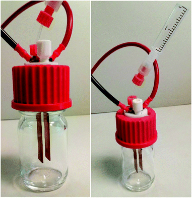 | ||
| Fig. 6 Our batch reaction setup, reprinted with permission from ref. 115. Copyright 2020 American Chemical Society. | ||
- electrode distance: 5 mm
- electrode size 10 × 50 mm2, submerged surface approximately 10 × 10 mm2
- 20 mL solvent
- 1 mmol substrate, 0.5 M
- 0.2 mmol TBA BF4, 0.1 M
- for z = 1, 1.2 F mol−1, 39 min
Trouble shooting
We have summarised parameter changes for electrochemical reactions in Table 4 and address typical problems encountered in electrochemical reactions in this trouble shooting section.| Reaction mode | Current | Potential | Resistance | Reaction rate | Selectivity | |
|---|---|---|---|---|---|---|
| Current ↑ | Galvanostatic | ↑ | ↑ | Constant | ↑ | Potentially compromised due to increased potential |
| Ohmic heating possible | ||||||
| Potential ↑ | Potentiostatic | ↑ | ↑ | Constant | ↑ | Potentially compromised due to increased potential |
| Surface area ↑ | Galvanostatic | Constant | ↓ | ↓ | Constant | Constant or better |
| Potentiostatic | ↑ | Constant | ↑ | Ohmic heating possible | ||
| Surface area ↓ | Galvanostatic | Constant | ↑ | ↑ | Constant | Potentially compromised due to increased potential |
| Potentiostatic | ↓ | Constant | ↓ | Constant or better | ||
| Electrode gap ↑ | Galvanostatic | Constant | ↑ | ↑ | Constant | Potentially compromised due to increased potential |
| Potentiostatic | ↓ | Constant | ↓ | Constant or better | ||
| Electrode gap ↓ | Galvanostatic | Constant | ↓ | ↓ | Constant | Constant or better |
| Potentiostatic | ↑ | Constant | ↑ | Ohmic heating possible | ||
| Electrolyte concentration ↑ | Galvanostatic | Constant | ↓ | ↓ | Constant | Constant or better |
| Potentiostatic | ↑ | Constant | ↑ | Ohmic heating possible | ||
| Electrolyte concentration ↓ | Galvanostatic | Constant | ↑ | ↑ | Constant | Constant or better |
| Potentiostatic | ↓ | Constant | ↓ | Potentially compromised due to increased current density | ||
| Stirring ↑ | Galvanostatic | Constant | ↓ | ↓ | Constant | Constant or better |
| Potentiostatic | ↑ | Constant | ↑ | Ohmic heating possible |
Under continuous flow conditions (see section Continuous reactor vessel) potentiostatic conditions are more reproducible for our systems. Due to the small interelectrode gap, the resistance between the two electrodes is small and a potential very close to the desired potential can be used. Cantillo and co-workers have discussed the advantages and disadvantages for galvanostatic and potentiostatic conditions for continuous reactions.108
Reaction types (with examples)
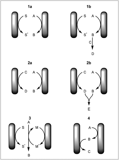
In this tutorial review we have focused on different types of reactions with respect to how and where the elementary redox steps occur rather than on different chemical transformations. This is to highlight different aspects of electrochemical mechanisms that should be considered when developing new methodologies in electrochemistry. The advantages of the setup employed will be discussed for each type of reaction. See the following reviews for specific transformations: cross coupling,24–26 CH activation,27–36 asymmetric synthesis,14 heterocycle formation,37–39 arylation,40 fluorination,41 organometallic catalysis,42,43 cation pool method.44The different types of reactions can be summarised as: (1) direct electrochemical reaction with solvent degradation as counter reaction, (2) direct electrochemical reaction with non-solvent degradation as counter reaction, (3) mediated or catalysed electrochemical reaction, (4) redox combined electrochemical reaction (Fig. 7).
(1) Direct electrochemical reaction with solvent degradation as counter reaction
A direct electrochemical reaction with solvent degradation as the counter reaction is the simplest case of an electrochemical reaction. A substrate is reduced or oxidised on the working electrode and the solvent is degraded as the counter reaction on the counter electrode (Fig. 7, 1a). As most electrochemical reactions produce radicals or other reactive and unstable intermediates, the substrate is very likely to react further to form a new product (Fig. 7, 1b). One example of this is the cation pool method, in which cations are produced electrochemically and after completion of this step a nucleophile is added to afford a new product.44
Wirth and co-workers have recently published an example of hypervalent iodine production from the oxidation of iodobenzene (Scheme 1).117 Fluorinated alcohols, either TFE or HFIP, were used as solvent. These functioned as the proton source for hydrogen evolution as the counter reaction and in addition the alkoxide then becomes a ligand on the iodine(III) compound. This reaction was performed in a continuous reactor to increase the productivity and then telescoped into a second continuous reactor, thereby coupling the electrochemical step with an oxidation reaction. In this manner the group has demonstrated the electrochemical synthesis of two hypervalent iodine compounds. These were then used to either oxidise a substrate or to produce bench-stable hypervalent iodine compounds via ligand exchange.
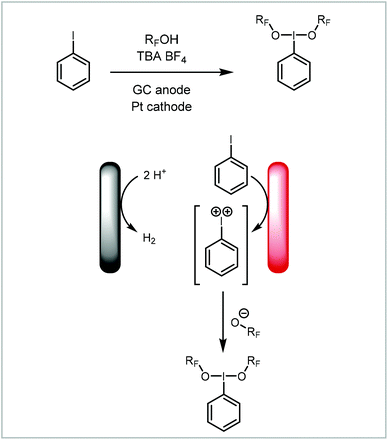 | ||
| Scheme 1 Electrochemical formation of hypervalent iodine compounds reported by Wirth and co-workers.117 | ||
Another example of the direct electrochemical reaction with solvent degradation as the counter reaction is the electrochemical formation of sulfonamides from amines and thiols reported by Noël and co-workers where the acidic, aqueous solution produces hydrogen at the cathode (Scheme 2).75 This process requires both starting materials to be oxidised, to the amine cation radical and disulfide respectively before combining to the sulfinamide. This is further oxidised to the sulfonamide via the sulfenamide. The reaction benefits from simple starting materials and mild synthetic conditions. The reaction has been performed both under batch and continuous conditions depending on the substrate and product properties. Generally, the reaction exhibited improved control and higher yields under continuous conditions, however for some examples solubility posed a problem and the reaction was performed in batch.
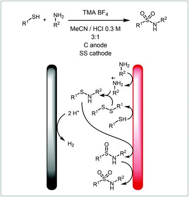 | ||
| Scheme 2 Electrochemical sulfonamide formation reported by Noël and co-workers.75 | ||
(2) Direct electrochemical reaction with non-solvent degradation as counter reaction
The counter reaction can be a reaction other than solvent degradation (Fig. 7, 2a). This can be particularly beneficial if (a) the counter reaction is rate limiting or is incompatible with the desired reaction, (b) the counter reaction can produce another useful material or (c) the products from both electrodes react to form a new product. Atobe and co-workers demonstrated that the counter reaction can be used to increase the efficiency of a process by performing another reaction of interest in a paired electrosynthesis (Scheme 3).118 Concurrent reductive dehalogenation to an alkane and oxidation of an alcohol to a ketone was performed using an indium tin oxide (ITO) anode and a silver cathode. Performing the reaction under parallel laminar flow conditions avoided further reaction of the products at the respective counter electrodes and avoided the use of a divided cell.
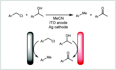 | ||
| Scheme 3 Paired electrosynthesis reported by Atobe and co-workers.118 | ||
In addition to forming two separate products, the synthesis can be coupled by these products reacting further to form a new product (Fig. 7, 2b). Our group has demonstrated the electrochemical formation of NHC-complexes where the an imidazolium salt is reduced to the NHC on the cathode and the anode metal is oxidised to release metal cations into solution (Scheme 4).67 The two products then react together to form the NHC complex. This method has been applied to a range of metals and also has been extended to salen ligands.119 Benefits of translating this coupled process into continuous flow include increased production rate and Faradaic efficiencies.71
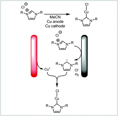 | ||
| Scheme 4 Electrochemical formation of metal-NHC complexes reported by Willans and co-workers.67,71,119 | ||
(3) Mediated or catalysed electrochemical reaction
Instead of oxidising or reducing the substrate directly, a mediator or catalyst can be used (Fig. 7, 3). This involves the use of a redox active species which then chemically oxidises or reduces the substrate in solution. This can be beneficial if the substrate's potential would otherwise be outside the solvent window. The use of a mediator or catalyst is very similar to traditional chemocatalysis, except that the catalyst is turned over electrochemically, therefore it is called an electrocatalyst. This avoids the use of terminal reductants or oxidants which improves atom economy and reduces waste streams.
One of the most commonly reported examples of an electrochemical mediator is the use of TEMPO (2,2,6,6-tetramethylpiperidin-1-yl)oxyl and other nitroxyradicals for the oxidation of alcohols. They can be oxidised to the oxoammonium cation which then oxidises the alcohol to a ketone forming a hydroxylamine. This can then be oxidised electrochemically to recover the nitroxyradical (Scheme 5).120 Brown and co-workers have developed a continuous flow protocol for the TEMPO-mediated electrooxidation of alcohols under particularly mild conditions and without the use of an electrolyte. The group used a carbon on PVDF (polyvinylidene fluoride) anode and a stainless steel (SS) cathode and demonstrated the versatility of the process on the oxidation of 13 substrates.
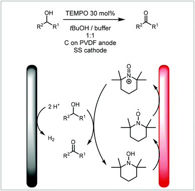 | ||
| Scheme 5 TEMPO mediated electrooxidation of alcohols reported by Brown and co-workers.120 | ||
Likewise, a more traditional catalyst can be used in a mediated electrosynthesis. In this case, the active species of the electrocatalyst is formed and/or turned over by electricity.28,30,32–34 This concept has also been applied to photocatalysts.121 Morrill and co-workers have developed the electrocatalysed deconstructive chlorination of cycloalkanols (Scheme 6).122 The manganese(II) catalyst is activated by addition of a chloride ligand before it is electrochemically oxidised to manganese(III). This species then chemically oxidises an alcohol to an alkoxy radical. After ring-opening, the radical is further oxidised by Mn(III) to the carbocation which is intercepted by chloride to form the final product. The group demonstrated the applicability of this mild electrochemical approach to a broad substrate scope and implemented a continuous protocol including inline purification to increase productivity and scale.
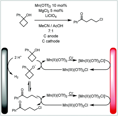 | ||
| Scheme 6 Manganese electrocatalytic synthesis of cycloalkanols reported by Morrill and co-workers.122 | ||
(4) Redox combined electrochemical reaction
A redox combined synthesis, also called domino-oxidation–reduction sequence, is a coupled process where the product formed on one electrode reacts further on the other electrode (Fig. 7, 4).123 This type of reaction benefits significantly from the use of continuous flow methods with small interelectrode gaps as the substrate has to diffuse from one electrode to the other. Atobe and co-workers investigated a redox combined synthesis of dibenzylamine from benzylamine under batch and continuous flow conditions (Scheme 7).124 The benzylamine first undergoes an oxidative dimerisation to the imine and then reduction to the dibenzylamine. When performing the reaction in batch, it was found that the reaction does not proceed to the dibenzylamine product but instead stops after the dimerisation, whereas in flow an equilibrium between N-benzylidinebenzylamine and dibenzylamine is achieved. This is attributed to the small interelectrode gap in the continuous flow reactor.
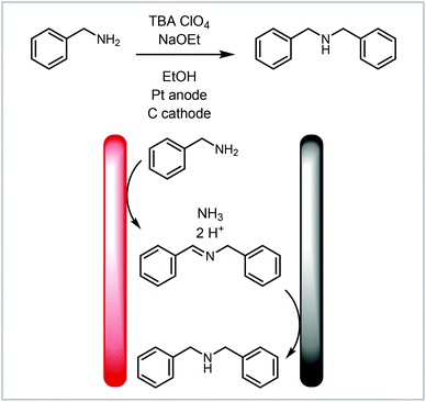 | ||
| Scheme 7 Redox combined synthesis to dibenzylamine from benzylamine reported by Atobe and co-workers.124 | ||
Analogously, Waldvogel and co-workers demonstrated the redox combined synthesis of nitriles from oximes via a nitrile-N-oxide (Scheme 8),125 thus avoiding the harsh reaction conditions found in traditional syntheses of this type. Translating the process into a continuous flow protocol increased the reaction yield significantly for challenging substrates such as 2,6-dichlorobenzaldoxime from 40% to 63%.96
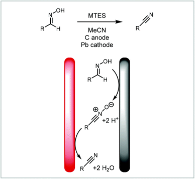 | ||
| Scheme 8 Domino-oxidation–reduction sequence of nitriles from oximes reported by Waldvogel and co-workers.96,125 | ||
Conclusion and outlook
In this tutorial review we have provided an easily accessible, modern introduction to electrochemistry to allow more researchers to explore the use of synthetic electrochemistry. It is aimed at lowering the perceived barrier to adoption of electrochemistry and increase the engagement of synthetic chemists in this exciting field. This tutorial review covers the mechanism and setup of an electrochemical reaction and recommendations on where to start when exploring electrochemistry. Examples to demonstrate the scope of synthetic electrochemistry are given.Electrochemistry is a sustainable way to achieve functional complexity in a mild, green and atom efficient way as electrons act as the reagents. Even though the use of stoichiometric amounts of electrolyte may be required, it can still offer major selectivity advantages over traditional chemical methods and therefore avoid protection/deprotection steps. As such, electrochemistry deserves the attention of a broader synthetic chemist community.
With nothing more than a power supply, a pair of appropriately selected electrodes and the knowledge contained within this tutorial, the synthetic chemist should feel confident in adopting electrochemistry as part of their synthesis toolkit.
Conflicts of interest
There are no conflicts to declare.Acknowledgements
The EPSRC (grant EP/R009406/1) and the University of Leeds are acknowledged for funding.References
- H. Lund, J. Electrochem. Soc., 2002, 149, S21–S33 CrossRef CAS.
- J. B. Sperry and D. L. Wright, Chem. Soc. Rev., 2006, 35, 605–621 RSC.
- J.-I. Yoshida, K. Kataoka, R. Horcajada and A. Nagaki, Chem. Rev., 2008, 108, 2265–2299 CrossRef CAS PubMed.
- B. A. Frontana-Uribe, R. D. Little, J. G. Ibanez, A. Palma and R. Vasquez-Medrano, Green Chem., 2010, 12, 2099–2119 RSC.
- S. R. Waldvogel and B. Janza, Angew. Chem., Int. Ed., 2014, 53, 7122–7123 CrossRef CAS PubMed.
- E. J. Horn, B. R. Rosen and P. S. Baran, ACS Cent. Sci., 2016, 2, 302–308 CrossRef CAS PubMed.
- M. Yan, Y. Kawamata and P. S. Baran, Chem. Rev., 2017, 117, 13230–13319 CrossRef CAS PubMed.
- D. S. P. Cardoso, B. Šljukić, D. M. F. Santos and C. A. C. Sequeira, Org. Process Res. Dev., 2017, 21, 1213–1226 CrossRef CAS.
- A. Wiebe, T. Gieshoff, S. Mohle, E. Rodrigo, M. Zirbes and S. R. Waldvogel, Angew. Chem., Int. Ed., 2018, 57, 5594–5619 CrossRef CAS PubMed.
- S. Mohle, M. Zirbes, E. Rodrigo, T. Gieshoff, A. Wiebe and S. R. Waldvogel, Angew. Chem., Int. Ed., 2018, 57, 6018–6041 CrossRef PubMed.
- M. Yan, Y. Kawamata and P. S. Baran, Angew. Chem., Int. Ed., 2018, 57, 4149–4155 CrossRef CAS PubMed.
- R. D. Little and K. D. Moeller, Chem. Rev., 2018, 118, 4483–4484 CrossRef CAS PubMed.
- K. D. Moeller, Chem. Rev., 2018, 118, 4817–4833 CrossRef CAS PubMed.
- M. Ghosh, V. S. Shinde and M. Rueping, Beilstein J. Org. Chem., 2019, 15, 2710–2746 CrossRef CAS PubMed.
- Y. Yuan and A. Lei, Nat. Commun., 2020, 11, 802 CrossRef CAS PubMed.
- Q. Jing and K. D. Moeller, Acc. Chem. Res., 2020, 53, 135–143 CrossRef CAS PubMed.
- H. J. Schäfer, in Radicals in Organic Synthesis, ed. P. Renaud and M. P. Sibi, Wiley, 2001, pp. 250–297, DOI:10.1002/9783527618293.ch14.
- Electrochemistry: Technology, Synthesis, Energy and Materials, Chem. Rev., 2018, 118(9), 4483–4886.
- S. D. Minteer and P. Baran, Acc. Chem. Res., 2020, 53, 545–546 CrossRef CAS PubMed.
- L. R. Faulkner, J. Chem. Educ., 1983, 60, 262–264 CrossRef CAS.
- P. T. Kissinger and A. W. Bott, Curr. Sep. Drug Dev., 2002, 20, 51–54 CAS.
- D. T. Sawyer, J. L. Roberts Jr. and A. Sobkowiak, Electrochemistry for chemists, Wiley, New York (N.Y.), 995 Search PubMed.
- C. Kingston, M. D. Palkowitz, Y. Takahira, J. C. Vantourout, B. K. Peters, Y. Kawamata and P. S. Baran, Acc. Chem. Res., 2020, 53, 72–83 CrossRef CAS PubMed.
- P. Wang, X. Gao, P. Huang and A. Lei, ChemCatChem, 2019, 12, 27–40 CrossRef.
- P. Wang, S. Tang, P. Huang and A. Lei, Angew. Chem., Int. Ed., 2017, 56, 3009–3013 CrossRef CAS PubMed.
- J. L. Röckl, D. Pollok, R. Franke and S. R. Waldvogel, Acc. Chem. Res., 2020, 53, 45–61 CrossRef PubMed.
- M. D. Kärkäs, Chem. Soc. Rev., 2018, 47, 5786–5865 RSC.
- L. Ackermann, Acc. Chem. Res., 2019, 53, 84–104 CrossRef PubMed.
- Y. Takahira, M. Chen, Y. Kawamata, P. Mykhailiuk, H. Nakamura, B. K. Peters, S. H. Reisberg, C. Li, L. Chen, T. Hoshikawa, T. Shibuguchi and P. S. Baran, Synlett, 2019, 30, 1178–1182 CrossRef CAS.
- J. Chen, S. Lv and S. Tian, ChemSusChem., 2019, 12, 115–132 CrossRef CAS PubMed.
- Q.-L. Yang, P. Fang and T.-S. Mei, Chin. J. Chem., 2018, 36, 338–352 CrossRef CAS.
- N. Sauermann, T. H. Meyer, Y. Qiu and L. Ackermann, ACS Catal., 2018, 8, 7086–7103 CrossRef CAS.
- Y. Qiu, A. Scheremetjew and L. Ackermann, J. Am. Chem. Soc., 2019, 141, 2731–2738 CrossRef CAS PubMed.
- C. Ma, P. Fang and T.-S. Mei, ACS Catal., 2018, 8, 7179–7189 CrossRef CAS.
- H. Wang, X. Gao, Z. Lv, T. Abdelilah and A. Lei, Chem. Rev., 2019, 119, 6769–6787 CrossRef CAS PubMed.
- S. Tang, Y. Liu and A. Lei, Chem, 2018, 4, 27–45 CAS.
- R. Francke, Beilstein J. Org. Chem., 2014, 10, 2858–2873 CrossRef PubMed.
- P. Xiong and H.-C. Xu, Acc. Chem. Res., 2019, 52, 3339–3350 CrossRef CAS PubMed.
- K. Yamamoto, M. Kuriyama and O. Onomura, Acc. Chem. Res., 2020, 53, 105–120 CrossRef CAS PubMed.
- S. R. Waldvogel, S. Lips, M. Selt, B. Riehl and C. J. Kampf, Chem. Rev., 2018, 118, 6706–6765 CrossRef CAS PubMed.
- T. Fuchigami and S. Inagi, Acc. Chem. Res., 2020, 53, 322–334 CrossRef CAS PubMed.
- A. Jutand, Chem. Rev., 2008, 108, 2300–2347 CrossRef CAS PubMed.
- K.-J. Jiao, Y.-K. Xing, Q.-L. Yang, H. Qiu and T.-S. Mei, Acc. Chem. Res., 2020, 53, 300–310 CrossRef CAS PubMed.
- J.-I. Yoshida, A. Shimizu and R. Hayashi, Chem. Rev., 2018, 118, 4702–4730 CrossRef CAS PubMed.
- J.-I. Yoshida, Electrochem. Soc. Interface, 2009, 18, 40–45 CAS.
- K. Watts, A. Baker and T. Wirth, J. Flow Chem., 2015, 4, 2–11 CrossRef.
- A. A. Folgueiras-Amador and T. Wirth, J. Flow Chem., 2017, 7, 94–95 CrossRef CAS.
- M. Atobe, Curr. Opin. Electrochem., 2017, 2, 1–6 CrossRef CAS.
- D. Pletcher, R. A. Green and R. C. D. Brown, Chem. Rev., 2018, 118, 4573–4591 CrossRef CAS PubMed.
- M. Atobe, H. Tateno and Y. Matsumura, Chem. Rev., 2018, 118, 4541–4572 CrossRef CAS PubMed.
- K. Mitsudo, Y. Kurimoto, K. Yoshioka and S. Suga, Chem. Rev., 2018, 118, 5985–5999 CrossRef CAS PubMed.
- A. A. Folgueiras-Amador and T. Wirth, in Flow Chemistry in Organic Synthesis, ed. T. F. Jamison and G. Koch, Georg Thieme Verlag, Stuttgart, 2018 edn, 2018, pp. 147–189, DOI:10.1055/sos-SD-228-00106..
- T. Noël, Y. Cao and G. Laudadio, Acc. Chem. Res., 2019, 52, 2858–2869 CrossRef PubMed.
- M. Elsherbini and T. Wirth, Acc. Chem. Res., 2019, 52, 3287–3296 CrossRef CAS PubMed.
- A. A. Folgueiras-Amador and T. Wirth, in Flow Chemistry: Integrated Approaches for Practical Applications, The Royal Society of Chemistry, 2020, pp. 153–198, 10.1039/9781788016094-00153.
- N. Elgrishi, K. J. Rountree, B. D. McCarthy, E. S. Rountree, T. T. Eisenhart and J. L. Dempsey, J. Chem. Educ., 2017, 95, 197–206 CrossRef.
- C. Sandford, M. A. Edwards, K. J. Klunder, D. P. Hickey, M. Li, K. Barman, M. S. Sigman, H. S. White and S. D. Minteer, Chem. Sci., 2019, 10, 6404–6422 RSC.
- R. H. Verschueren and W. M. D. Borggraeve, Molecules, 2019, 24, 2122–2160 CrossRef PubMed.
- H. Helmholtz, Ann. Phys., 1853, 165, 211–233 CrossRef.
- Á. Molina, J. González, F. Martínez-Ortiz and R. G. Compton, J. Phys. Chem. C, 2010, 114, 4093–4099 CrossRef.
- Y. Huang, X. Chong, C. Liu, Y. Liang and B. Zhang, Angew. Chem., Int. Ed., 2018, 57, 13163–13166 CrossRef CAS PubMed.
- W. M. Haynes, CRC handbook of chemistry and physics, CRC Press, 2014 Search PubMed.
- H. G. Roth, N. A. Romero and D. A. Nicewicz, Synlett, 2016, 27, 714–723 CAS.
- M. E. G. Lyons, R. L. Doyle, M. P. Browne, I. J. Godwin and A. A. S. Rovetta, Curr. Opin. Electrochem., 2017, 1, 40–45 CrossRef CAS.
- V. V. Pavlishchuk and A. W. Addison, Inorg. Chim. Acta, 2000, 298, 97–102 CrossRef CAS.
- L. M. Reid, T. Li, Y. Cao and C. P. Berlinguette, Sustainable Energy Fuels, 2018, 2, 1905–1927 RSC.
- B. R. M. Lake, E. K. Bullough, T. J. Williams, A. C. Whitwood, M. A. Little and C. E. Willans, Chem. Commun., 2012, 48, 4887–4889 RSC.
- E. E. Finney, K. A. Ogawa and A. J. Boydston, J. Am. Chem. Soc., 2012, 134, 12374–12377 CrossRef CAS PubMed.
- T. Gieshoff, A. Kehl, D. Schollmeyer, K. D. Moeller and S. R. Waldvogel, Chem. Commun., 2017, 53, 2974–2977 RSC.
- C. Gütz, B. Klöckner and S. R. Waldvogel, Org. Process Res. Dev., 2016, 20, 26–32 CrossRef.
- M. R. Chapman, Y. M. Shafi, N. Kapur, B. N. Nguyen and C. E. Willans, Chem. Commun., 2015, 51, 1282–1284 RSC.
- E. J. Horn, B. R. Rosen, Y. Chen, J. Tang, K. Chen, M. D. Eastgate and P. S. Baran, Nature, 2016, 533, 77–81 CrossRef CAS PubMed.
- Y. Kawamata, M. Yan, Z. Liu, D.-H. Bao, J. Chen, J. T. Starr and P. S. Baran, J. Am. Chem. Soc., 2017, 139, 7448–7451 CrossRef CAS PubMed.
- C. Li, Y. Kawamata, H. Nakamura, J. C. Vantourout, Z. Liu, Q. Hou, D. Bao, J. T. Starr, J. Chen, M. Yan and P. S. Baran, Angew. Chem., Int. Ed., 2017, 56, 13088–13093 CrossRef CAS PubMed.
- G. Laudadio, E. Barmpoutsis, C. Schotten, L. Struik, S. Govaerts, D. L. Browne and T. Noël, J. Am. Chem. Soc., 2019, 141, 5664–5668 CrossRef CAS PubMed.
- L. Schulz, M. Enders, B. Elsler, D. Schollmeyer, K. M. Dyballa, R. Franke and S. Waldvogel, Angew. Chem., Int. Ed., 2017, 56, 4877–4881 CrossRef CAS PubMed.
- B. Riehl, K. M. Dyballa, R. Franke and S. R. Waldvogel, Synthesis, 2017, 252–259 CAS.
- redox.me, https://redox.me/, (accessed 16/01/20).
- P. S. Baran, E. Horn and D. Waldmann, 2018, US 2018/0217096 A1, Closure for an Electrochemical Vessel, Electrochemical Vessel and Laboratory Device.
- IKA, https://www.ika.com/en/Products-Lab-Eq/Electrochemistry-Kit-csp-516/ElectraSyn-20-Package-cpdt-20008980/, (accessed 20/01/20).
- A. G. O'Brien, A. Maruyama, Y. Inokuma, M. Fujita, P. S. Baran and D. G. Blackmond, Angew. Chem., Int. Ed., 2014, 53, 11868–11871 CrossRef PubMed.
- Alvatek, https://www.alvatek.co.uk/h-cell/, (accessed 16/01/20).
- Adams&Chittenden, http://www.adamschittenden.com/Gallery.html?category=4, (accessed 16/01/20).
- A. A. Folgueiras-Amador, A. E. Teuten, D. Pletcher and R. C. D. Brown, React. Chem. Eng., 2020, 5, 712–718 RSC.
- D. Simonsson, J. Appl. Electrochem., 1984, 14, 595–604 CrossRef CAS.
- C. Vallières and M. Matlosz, J. Electrochem. Soc. India, 1999, 146, 2933–2939 CrossRef.
- V. Mengeaud, O. Bagel, R. Ferrigno, H. H. Girault and A. Haider, Lab Chip, 2002, 2, 39–44 RSC.
- M. Küpper, V. Hessel, H. Löwe, W. Stark, J. Kinkel, M. Michel and H. Schmidt-Traub, Electrochim. Acta, 2003, 48, 2889–2896 CrossRef.
- J.-I. Yoshida, Chem. Commun., 2005, 36, 4509–4516 RSC.
- R. Horcajada, M. Okajima, S. Suga and J.-I. Yoshida, Chem. Commun., 2005, 10, 1303–1305 RSC.
- P. He, P. Watts, F. Marken and S. J. Haswell, Lab Chip, 2007, 7, 141–143 RSC.
- A. Attour, S. Rode, A. Ziogas, M. Matlosz and F. Lapicque, J. Appl. Electrochem., 2008, 38, 339–347 CrossRef CAS.
- K. Watts, W. Gattrell and T. Wirth, Beilstein J. Org. Chem., 2011, 7, 1108–1114 CrossRef CAS PubMed.
- A. Attour, P. Dirrenberger, S. Rode, A. Ziogas, M. Matlosz and F. Lapicque, Chem. Eng. Sci., 2011, 66, 480–489 CrossRef CAS.
- C. Gütz, M. Bänziger, C. Bucher, T. R. Galvão and S. R. Waldvogel, Org. Process Res. Dev., 2015, 19, 1428–1433 CrossRef.
- C. Gütz, A. Stenglein and S. R. Waldvogel, Org. Process Res. Dev., 2017, 21, 771–778 CrossRef.
- L.-D. Syntrivanis, F. J. d. Campo and J. Robertson, J. Flow Chem., 2018, 8, 123–128 CrossRef CAS.
- G. Laudadio, W. de Smet, L. Struik, Y. Cao and T. Noël, J. Flow Chem., 2018, 8, 157–165 CrossRef PubMed.
- C. G. W. van Melis, M. R. Penny, A. D. Garcia, A. Petti, A. P. Dobbs, S. T. Hilton and K. Lam, J. Flow Chem., 2019, 6, 4144–4148 CAS.
- R. A. Green, R. C. D. Brown, D. Pletcher and B. Harji, Org. Process Res. Dev., 2015, 19, 1424–1427 CrossRef CAS.
- CRD, https://www.cambridgereactordesign.com/ammonite/ammonite.html, (accessed 16/01/20).
- A. A. Folgueiras-Amador, K. Philipps, S. Guilbaud, J. Poelakker and T. Wirth, Angew. Chem., Int. Ed., 2017, 56, 15446–15450 CrossRef CAS PubMed.
- Vapourtec, https://www.vapourtec.com/products/flow-reactors/ion-electrochemical-reactor-features/, (accessed 16/01/20).
- Syrris, https://syrris.com/product/asia-electrochemistry-flow-chemistry-system/, (accessed 16/01/20).
- F. F. Rivera, C. P. de León, J. L. Nava and F. C. Walsh, Electrochim. Acta, 2015, 163, 338–354 CrossRef CAS.
- R. A. Green, R. C. D. Brown and D. Pletcher, J. Flow Chem., 2015, 5, 31–36 CrossRef CAS.
- T. P. Nicholls, C. Schotten and C. E. Willans, Current Opin. Green Sustainable Chem., 2020 Search PubMed , accepted.
- S. Maljuric, W. Jud, C. O. Kappe and D. Cantillo, J. Flow Chem., 2020, 10, 181–190 CrossRef CAS.
- L. Schulz and S. Waldvogel, Synlett, 2018, 30, 275–286 Search PubMed.
- R. Francke, D. Cericola, R. Kötz, D. Weingarth and S. R. Waldvogel, Electrochim. Acta, 2012, 62, 372–380 CrossRef CAS.
- O. R. Luca, J. L. Gustafson, S. M. Maddox, A. Q. Fenwick and D. C. Smith, Org. Chem. Front., 2015, 2, 823–848 RSC.
- D. Polcari, P. Dauphin-Ducharme and J. Mauzeroll, Chem. Rev., 2016, 116, 13234–13278 CrossRef CAS PubMed.
- T. Fuchigami, M. Atobe and S. Inagi, Fundamentals and applications of organic electrochemistry: synthesis, materials, devices, John Wiley & Sons, 2014 Search PubMed.
- C. Stang and F. Harnisch, ChemSusChem, 2016, 9, 50–60 CrossRef CAS PubMed.
- H. R. Stephen, C. Schotten, T. P. Nicholls, M. Woodward, R. A. Bourne, N. Kapur and C. E. Willans, Org. Process Res. Dev., 2020 DOI:10.1021/acs.oprd.0c00091.
- J. Xiang, M. Shang, Y. Kawamata, H. Lundberg, S. H. Reisberg, M. Chen, P. Mykhailiuk, G. Beutner, M. R. Collins, A. Davies, M. Del Bel, G. M. Gallego, J. E. Spangler, J. Starr, S. Yang, D. G. Blackmond and P. S. Baran, Nature, 2019, 573, 398–402 CrossRef CAS PubMed.
- M. Elsherbini, B. Winterson, H. Alharbi, A. A. Folgueiras-Amador, C. Génot and T. Wirth, Angew. Chem., Int. Ed., 2019, 58, 9811–9815 CrossRef CAS PubMed.
- F. Amemiya, D. Horii, T. Fuchigami and M. Atobe, J. Electrochem. Soc., 2008, 155, E162–E165 CrossRef CAS.
- M. R. Chapman, S. E. Henkelis, N. Kapur, B. N. Nguyen and C. E. Willans, ChemistryOpen, 2016, 5, 351–356 CrossRef CAS PubMed.
- J. T. Hill-Cousins, J. Kuleshova, R. A. Green, P. R. Birkin, D. Pletcher, T. J. Underwood, S. G. Leach and R. C. D. Brown, ChemSusChem, 2012, 5, 326–331 CrossRef CAS PubMed.
- J. P. Barham and B. König, Angew. Chem., Int. Ed., 2019 DOI:10.1002/anie.201913767.
- B. D. W. Allen, M. D. Hareram, A. C. Seastram, T. McBride, T. Wirth, D. L. Browne and L. C. Morrill, Org. Lett., 2019, 21, 9241–9246 CrossRef CAS PubMed.
- C. A. Paddon, M. Atobe, T. Fuchigami, P. He, P. Watts, S. J. Haswell, G. J. Pritchard, S. D. Bull and F. Marken, J. Appl. Electrochem., 2006, 36, 617–634 CrossRef CAS.
- F. Amemiya, T. Kashiwagi, T. Fuchigami and M. Atobe, Chem. Lett., 2011, 40, 606–608 CrossRef CAS.
- M. F. Hartmer and S. R. Waldvogel, Chem. Commun., 2015, 51, 16346–16348 RSC.
| This journal is © The Royal Society of Chemistry 2020 |

