 Open Access Article
Solvometallurgical process for extraction of copper from chalcopyrite and other sulfidic ore minerals†
Xiaohua
Li
 *a,
Wouter
Monnens
b,
Zheng
Li
 a,
Jan
Fransaer
b and
Koen
Binnemans
 a
a
aKU Leuven, Department of Chemistry, Celestijnenlaan 200F, P.O. box 2404, B-3001 Leuven, Belgium. E-mail: xiaohua.li@kuleuven.be
bKU Leuven, Department of Materials Engineering, Kasteelpark Arenberg 44, bus 2450, B-3001 Heverlee, Belgium
First published on 13th December 2019
Abstract
Extraction of copper from sufidic ores, either by pyrometallurgy or hydrometallurgy, has various limitations. In this study, a solvometallurgical process for the extraction of copper from sulfidic ore minerals (chalcopyrite, bornite, chalcocite and digenite) was developed by using an organic lixiviant (FeCl3 as oxidizing agent and ethylene glycol (EG) as organic solvent). All the studied copper sulfide minerals could be leached efficiently with a FeCl3–EG solution. Other lixiviant systems, namely CuCl2–EG, FeCl3–ethanol and FeCl3–propylene glycol could also extract copper, but they did not perform as well as the FeCl3–EG solutions. The mechanistic study of chalcopyrite leaching in FeCl3–EG solutions confirmed that the leaching products of chalcopyrite were FeCl2, CuCl and solid elemental sulfur, where the Fe(II) and Cu(I) were quantified by UV-Vis absorption spectroscopy and solid sulfur was identified by powder XRD. A kinetic study showed that the leaching process was a surface chemical controlled process and the apparent activation energy was calculated to be 60.1 kJ mol−1. Subsequently, electrodeposition of copper from the pregnant leachate was investigated, and SEM-EDX analysis showed that uniform cubic crystalline deposits of pure copper were produced. Meanwhile, the Fe(III) was regenerated by oxidizing Fe(II) at the anode, with a Morgane membrane in between two electrode compartments to prevent the transfer of Fe(III) to the cathode. Finally, a closed-loop solvometallurgical process was designed with three operational steps: leaching, electrodeposition and removal of Fe(II). The regeneration of the FeCl3–EG solution and the use of EG contribute to the sustainability and the greenness of the process.
Introduction
Copper can be extracted from various types of ores, most of which belong to the sulfidic ores such as chalcopyrite, bornite, covellite, digenite and chalcocite. Chalcopyrite is the most common copper-bearing mineral and accounts for approximately 70% of the copper deposits in the world.1 At present, the main method for copper production from chalcopyrite is via pyrometallurgy, but it is only economically feasible for copper-rich feeds. Moreover, SO2 emissions can cause environmental problems. Hydrometallurgy is an alternative method for copper extraction from chalcopyrite, which can be applied to low grade copper ores due to the lower operating costs.2Many works have been reported for hydrometallurgical leaching of chalcopyrite. The most often used lixiviants are acidic chloride media, acidic sulfate media and basic ammonia solutions, together with various oxidizing agents.3–7 The most often used oxidizing agents are oxygen, ferric sulfate, ferric chloride or cupric chloride.8–13 Various other oxidizing agents were investigated as well, such as hydrogen peroxide, ammonium persulfate, hypochlorite and ozone.14–17 All these studied processes can leach copper to some extent, but there are some disadvantages. In sulfate media, the leaching kinetics are generally slow (several months) and the leaching of copper is difficult to be complete, due to the formation of passivation layers on the surface of chalcopyrite, such as solid sulfur and iron precipitate (e.g. jarosite).1 In chloride media, the leaching rate is faster than that in sulfate media, due to the high solubility of salts in chloride media and the fact that the cuprous ions can be stabilized in concentrated chloride solutions, so that the Cu(I)/Cu(II) redox couple could contribute to the oxidation of chalcopyrite. Moreover, the oxidation product of S2− is likely elemental sulfur in chloride media instead of sulfate, which is an advantage because solid elemental sulfur is easier to store and less neutralizing agent is needed in the downstream processing. However, the disadvantages of chloride media are their corrosivity and the difficulty of electrowinning high-grade copper from chloride media.4 Bioleaching has been studied for copper leaching from chalcopyrite as well, but the leaching rates are very slow. It can take months to reach the maximum leaching yield.18 In acidic leaching, high concentrations of acid are needed to avoid the formation of a passivation layer of iron precipitate, when ferric oxidizing agents are used. To overcome the problem of low extraction rate, leaching of chalcopyrite is typically done at high temperatures and high pressures in an autoclave at industrial scale,13 but this requires a high capital investment and high energy consumption. In summary, pyrometallurgy, hydrometallurgy and bioleaching all have their limitations, and hence it is important to develop new green and sustainable metallurgy technologies to improve the efficiency of copper extraction from copper sulfide ores.
Solvometallurgy is an emerging technology for metal processing, where little or no water is involved in the process. It is complementary to hydrometallurgy and pyrometallurgy. The examples of solvometallurgy are solvoleaching,19,20 non-aqueous solvent extraction21–24 and non-aqueous electrodeposition.25 If ionic liquids or deep-eutectic solvents are employed, one also speaks of ionometallurgy.26,27 Solvoleaching is in some cases more selective than acidic aqueous leaching. Deep-eutectic solvents containing iodine can be used for dissolution of sulfide minerals.28–30 Copper-containing sulfidic gold ores have been leached in ionic liquids.31 Different authors have investigated the leaching of copper from the sulfidic copper ore chalcopyrite using ionic liquids.32–36 The addition of polar organic solvents such as alcohols to the aqueous acidic solutions can increase the copper extractions.37–40 Methanesulfonic acid, an organic acid was used as an alternative for mineral acid for extraction of copper from chalcopyrite.41,42 However, these systems were in general water-rich processes.
In this paper, we describe a green solvometallurgical process for the extraction of copper from sulfidic ore minerals, with the emphasis on chalcopyrite. The preferred organic solvent is ethylene glycol with FeCl3 as the oxidizing agent. Ethylene glycol (EG) is a recommended green solvent according to the CHEM21 selection guide and the Global Harmonized System (GHS).43 Moreover, it can be produced from renewable sources such as cellulose.44 To have a sustainable process, electrodeposition of copper directly from the pregnant leachate is studied to remove copper and to regenerate simultaneously the oxidizing agent FeCl3. Finally, a closed-loop process flow sheet is proposed.
Experimental
Materials
Ethylene glycol (99.5%), iron(III) chloride (98%), copper(II) chloride (99%), 1,10-phenanthroline (>99%) and ethanol (99.5%) were ordered from Acros Organics (Geel, Belgium). Propylene glycol (99.5%), nitric acid (65 wt%), potassium chloride (99.9%) and ascorbic acid (99%) were purchased from Sigma-Aldrich (Diegem, Belgium). Lithium chloride (>98.5%) and 2,9-dimethyl-1,10-phenanthroline (neocuproine, 99%) were ordered from Fisher Scientific (Merelbeke, Belgium). Iron, copper and indium standard solutions (1000 ± 10 mg L−1) were purchased from Chem-Lab (Zedelgem, Belgium).Four sulfidic ore minerals, chalcopyrite from Bad Grund (Germany), chalcocite and bornite from Kesebol (Sweden), and digenite from Repparfjord (Norway) were purchased from M. Jentsch Mineralien und Rohsteine (Germany). Chalcopyrite from Morocco and chalcocite from Mexico were purchased from Northern Geological Supplies Ltd (UK). The received minerals were homogenized by grinding with a disc mill (Fritsch Pulverisette 13), after which the entire sample was sieved to get a particle size of <500 μm. Automatic shaking sieves, Analysette 3 Spartan by Fritsch, were used to separate the powders to two fractions. The fractions with particle size <250 μm were used in this work.
Leaching procedures
Leaching of the sulfidic ore minerals was performed in 4 mL glass vials and all the leaching solutions were stirred with magnetic stirring bars at 800 rpm for 24 h. Samples of the sulfidic ore minerals (50 mg) were mixed with 1 mL of FeCl3 in ethylene glycol (0.5 mol L−1) at 90 °C. The parameters for leaching of chalcopyrite were optimized by varying the temperature (22, 60 and 90 °C), the concentration of FeCl3 (0.1–1 mol L−1) and the solid-to-liquid ratio (30–150 g L−1). The effect of different oxidizing agents was studied by mixing 50 mg of chalcopyrite with 1 mL of EG containing 0.5 mol L−1 of oxidizing agent at 60 °C. The tested oxidizing agents include iron(III) chloride and copper(II) chloride. The solvent effect was studied at similar conditions where 0.5 mol L−1 of FeCl3 was dissolved in ethylene glycol, propylene glycol or ethanol.The leaching kinetics of chalcopyrite with 0.5 mol L−1 of FeCl3 in ethylene glycol were studied at different temperatures, where 500 mg of solid was mixed with 10 mL of leaching agent. Aliquots of leachate were taken out for analysis at given time.
The metal concentrations in all the leachate samples were measured with inductively-coupled plasma optical emission spectrometry (ICP-OES). The leaching percentage of metals were calculated according to eqn (1):
 | (1) |
Electrochemistry
Electrochemical experiments were performed using a three-electrode setup. The cell (PermeGear, USA) consisted of two compartments, separated by a Morgane membrane (Solvay, Belgium) in which the working electrode (WE) and the reference electrode (RE) were submersed in one compartment and the counter electrode (CE) was submersed in the second compartment. The WE consisted of a platinum-coated silicon wafer plate (Pt layer of 100 nm) and the CE was a coiled platinum wire whose surface area was at least five times larger than that of the WE. Preceding the experiments, the WE and CE were washed with hydrochloric acid (37% HCl) to remove possible impurities and were subsequently rinsed with demineralized water and acetone, and dried in a hot air flow. The RE was a silver/silver chloride (Ag/AgCl) electrode that consisted of a glass tube with frit, filled with a solution of 1 mol L−1 of KCl in ethylene glycol, in which an Ag/AgCl wire was submersed. The Ag/AgCl wire was prepared by the following procedure: an Ag wire was degreased using acetone, and eroded in 3 mol L−1 nitric acid. Next, the wire was rinsed using demineralized water and dried. After the aforementioned cleaning steps, the wire was anodized in 0.1 mol L−1 HCl by applying a current density of 0.1 A dm−2 for 15 min, leading the formation of a AgCl paste on the surface of the wire. For this anodization, a platinum substrate was used as cathode. All electrochemical measurements were performed using an Autolab PGSTAT 302N electrochemical interface controlled by a computer with NOVA software. Cyclic voltammograms (CVs) were measured in stationary conditions whereas electrochemical depositions were measured whilst stirring at 400 rpm. All measurements were performed at room temperature and in ambient atmosphere.Analytical techniques
The mineralogical composition of the chalcopyrite powder and solid residues were characterized by a X-ray diffraction analysis (D2 Phaser, Bruker, Germany) with Cu Kα radiation (30 kV, 10 mA in the measurement range 2θ of 20–70°). Data processing was performed with the X'Pert HighScore software.A Speedwave Xpert microwave digester, (Berghof, Germany) was used to dissolve the mineral solids in aqueous solutions by mixing 50 mg of solid with 7 mL of 65 wt% HNO3 in a DAP-40 pressure vessel at high temperature and pressure. The temperature and pressure setting of the digestion program are given in Table S1 in the ESI.†
Inductively-coupled plasma optical emission spectrometry (ICP-OES, Optima 8300, PerkinElmer) was used to measure the metal contents in the leachates and digested samples. A series of standard solutions containing iron(III) and copper(II) ions were analyzed to obtain calibration curves for sample analysis with indium as the internal standard.
UV-Vis absorption spectra were measured on a Varian Cary 5000 spectrophotometer with a wavelength resolution of 1.0 nm to quantify the concentration of copper(I) and iron(II) in the leachates. Neocuproine was used as colorimetric agent for copper(I).45 A 40 μL aliquot of the leachate was diluted in 2 mL of ethylene glycol, then 100 μL of the above solution was mixed with 1 mL of neocuproine solution (0.12 wt%), 1 mL of buffer solution and 3 mL of milliQ water. The sodium acetate buffer solution was prepared by mixing equal volumes of 6 mol L−1 of acetic acid and 5 mol L−1 of sodium hydroxide. The standard solutions of CuCl were prepared from CuCl2 in ethylene glycol solution which was reduced quantitatively by ascorbic acid. Lithium chloride was added to increase the solubility of CuCl in ethylene glycol.
1,10-Phenanthroline was used as colorimetric agent for quantification of iron(II) in the leachate solutions by UV-Vis absorption spectroscopy.46 The samples were prepared by mixing 100 μL of 50 times diluted leachate with 1 mL of 1,10-phenanthroline solution (0.12 wt%), 1 mL of buffer solution and 7.9 mL of milliQ water. The buffer solution was made with the same method as above mentioned. The standard solutions were prepared with different concentrations of iron(II) chloride.
The morphology and elemental composition of the films were analyzed by scanning electron microscopy (SEM; Phillips XL-30 FEG) and energy-dispersive X-ray spectroscopy (EDS; Octane elite super silicon drift detector, Ametek EDAX).
Results and discussion
Leaching of sulfide minerals
The leaching behavior of six different copper sulfide ore minerals has been studied: chalcopyrite from Bad Grund (Germany), chalcocite and bornite from Kesebol (Sweden), and digenite from Repparfjord (Norway), as well as chalcopyrite from Marocco (unspecified mine) and chalcocite from Mexico (unspecified mine). The metal contents in the studied sulfide minerals were determined with ICP-OES, after being digested with 65% nitric acid at high temperatures and high pressures in a microwave digestion instrument (Table 1). In all mineral samples, the copper contents were lower than the theoretic maximum value, indicating some gangue materials were also present. In some mineral samples, other metal impurities such as lead, zinc, magnesium, calcium were present as well.| Samples | Composition main phase | max. Cu content (wt%) | Cu (wt%) | Fe (wt%) | Other (wt%) |
|---|---|---|---|---|---|
| a No other metals were detected. | |||||
| Chalcopyrite Germany | CuFeS2 | 34.6 | 21.9 | 19.5 | —a |
| Chalcopyrite Morocco | CuFeS2 | 34.6 | 16.4 | 26.2 | Pb (3.9); Zn (0.5) |
| Chalcocite Sweden | Cu2S | 79.9 | 24.9 | 4.1 | Mn (6.6); Ca (1.8) |
| Chalcocite Mexico | Cu2S | 79.9 | 58.0 | 0.4 | — |
| Digenite Norway | Cu9S5 | 78.1 | 6.1 | 1.8 | — |
| Bornite Sweden | Cu5FeS4 | 63.3 | 26.0 | 5.8 | Mn (3.1); Ca(2.0) |
The leaching percentages of copper in 0.5 mol L−1 of FeCl3 in ethylene glycol for the different sulfidic ore minerals are presented in Fig. 1. Copper could be extracted completely from all copper mineral investigated, except from chalcocite. The leaching percentages of Cu from some minerals were higher than 100%, which results from the analytical error and inhomogeneous solid samples. Copper in chalcocite (Mexico) was not 100% leached, probably due to the insufficient amount of FeCl3 oxidizing agent, because the copper content in this mineral is very high (58.0 wt%). In other words, copper in chalcocite could be extracted quantitatively if higher concentrations of FeCl3 in ethylene glycol were used as leaching agent. Among the sulfidic copper minerals, chalcopyrite is the most difficult one for extraction of copper. The chalcopyrite sample of Germany contains a higher copper content and a lower iron content than the sample of Morocco. Therefore, chalcopyrite (Germany) was selected for further study of the leaching parameters. Note that the leaching behaviour of the impurities needs to be studied as well for some minerals such as chalcocite and bornite from Sweden.
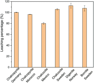 | ||
| Fig. 1 Leaching percentage of Cu with 0.5 mol L−1 of FeCl3 in ethylene glycol for different mineral powders at a solid-to-liquid ratio of 50 g L−1 at 90 °C for 24 h. | ||
Leaching of chalcopyrite
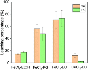
Leaching of copper from chalcopyrite was first studied with different solvents and oxidizing agents at 60 °C. The following organic solvents were used for chalcopyrite leaching: ethanol (EtOH), propylene glycol (PG) and ethylene glycol (EG) (Fig. 2). The solvent has a significant effect on the leaching efficiency of iron and copper, when the same concentration of FeCl3 was used as oxidizing agent. Among all three solvents, EG performed the best in terms of leaching efficiency. The lowest leaching efficiency in ethanol as solvent is probably due to its poor solvating property for the produced metal ions. PG and EG both have two symmetric hydroxyl functional groups per molecule which can coordinate bidentately to metal ions. However, PG has a much higher viscosity than EG, which could cause the slow leaching rate. Therefore, EG was selected as solvent for further study.Subsequently, the oxidizing agent CuCl2 was compared to FeCl3 for its leaching performance, both dissolving in ethylene glycol (Fig. 2). Whereas it was observed in hydrometallurgical leaching processes that CuCl2 shows faster leaching kinetics than FeCl3,4,8 this is not the case in our solvometallurgical process. The slow kinetics of CuCl2 in organic solvents are probably due to the lower oxidation potential of cupric ion in organic solvent. Therefore, FeCl3 in EG was selected as the leaching agent for further study.
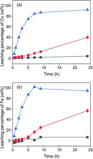
The effect of temperature on the leaching of chalcopyrite was investigated at room temperature (22 °C), 60 °C and 90 °C. The results in Fig. 3 show that at room temperature nearly no metal was leached. When increasing the temperature to 60 °C, iron and copper were leached linearly and after 24 h reached 57% and 40% respectively. When increasing to 90 °C, leaching of copper reached 90% after about 10 h and leaching of iron reached 100% after about 7 h. Clearly, the temperature has a significant influence on the metal extraction. However, not 100% of copper was leached even at 90 °C after 24 h. This might be due to the lack of a sufficient amount of oxidizing agent, as shown in the next section. Moreover, the EG–FeCl3 system has higher leaching rate of copper than the conventional H2O–FeCl3 system under the same experimental conditions. For example, less than 25% of copper was extracted from chalcopyrite crystal (<38 μm) with 0.5 mol L−1 FeCl3 in acidic aqueous solutions after 3 h at 90 °C,8 while almost 60% of copper was extracted from chalcopyrite powders (<250 μm) with EG–FeCl3 system under the same conditions (temperature, time and concentration of FeCl3).
The concentration of iron(III) in the leaching solutions was further varied to study the influence of the amount of oxidizing agent on the leaching efficiency. Fig. 4 shows that hardly was any copper leached with 0.1 mol L−1 of FeCl3 in EG. With more FeCl3 present in the leaching solution, more copper and iron were dissolved. The leaching percentage of copper increased to 80% with 0.5 mol L−1 of FeCl3. In other words, 1 mL of 0.5 mol L−1 of FeCl3 in EG could extract copper from 40 mg of chalcopyrite quantitatively. When further increasing the FeCl3 concentration to 1 mol L−1, all the copper and iron were extracted from the chalcopyrite sample. As expected, the concentration of the oxidizing agent plays an important role in the leaching process.
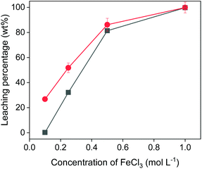 | ||
| Fig. 4 Effect of FeCl3 concentration on leaching of Cu (■) and Fe (●) from chalcopyrite. The leaching conditions were 800 rpm, 24 h, 90 °C and the solid-to-liquid ratio was 50 g L−1. | ||
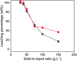
When varying the solid-to-liquid ratio (Fig. 5), it was observed that 100% of copper and iron could be extracted with 1 mL of 0.5 mol L−1 of FeCl3 in EG, when 30 or 40 mg of solids were added. This is in agreement with the observations from Fig. 4. With more added solid, the leaching efficiency further decreased. The decrease of the leaching efficiency of Cu was worse than that of Fe from chalcopyrite is probably due to the poorer solubility of the oxidizing product CuCl than that of FeCl2 in the organic leachate solutions. Both Fig. 4 and 5 confirmed that all the copper can be extracted from chalcopyrite as long as the amount of FeCl3 oxidizing agent is sufficient. Moreover, the observed complete copper extraction confirms that the solid surface was not passivated.
Leaching mechanism
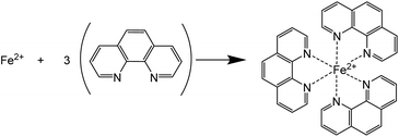
Chalcopyrite is most often considered to be Cu+Fe3+(S2−)2 rather than in the Cu2+Fe2+(S2−)2 valence state.1 In most of the hydrometallurgical processes, iron and copper are leached in the aqueous solutions in the form of Fe(II) and Cu(II) ions. The sulfide ions in chalcopyrite are likely oxidized to elemental sulfur in acidic media. The elemental sulfur may be further oxidized to sulfate with excess oxidant at a slower reaction rate.47 In this work, the leaching reaction mechanism, i.e. the oxidation states of iron, copper and sulfur in the pregnant leachate solutions was investigated.The oxidation state of iron in the leachates was identified with UV-Vis absorption spectroscopy. 1,10-Phenanthroline (phen) was used as a chelating colorimetric agent for Fe(II) cations (Scheme 1).46
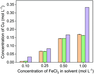
The formed complex [Fe(phen)3]2+ gives an orange color and an absorption maximum at 511 nm in acidic aqueous solutions when the pH is in the range of 4–7 (see Fig. S1†). The concentration of Fe(II) in the solution was quantified by measuring the absorbance of the solution. The concentration of Fe(II) was measured in four leachates, which were obtained by leaching chalcopyrite with four different FeCl3 concentrations at a solid-to-liquid ratio of 50 g L−1. The UV-Vis absorption spectra are shown in Fig. S1.† The amount of Fe(II) was compared with the total amount of iron in the leachates that was determined by ICP-OES (Fig. 6). When FeCl3 in the initial leaching agent was ≤0.5 mol L−1, the amount of iron in the leachates determined by UV-Vis absorption spectroscopy was nearly the same as that determined by ICP-OES, suggesting all Fe(III) has involved in the oxidative leaching and been reduced to Fe(II). This result confirms that the incomplete leaching of chalcopyrite is due to an insufficient amount of FeCl3 oxidizing agent. When sufficient FeCl3 was present (e.g. 1 mol L−1), complete leaching of Cu and Fe was achieved (Fig. 4), and the amount of total Fe was higher than that of Fe(II), indicating that an excess of Fe(III) remained in the leachate and more solids could be leached. Therefore, it can be concluded that the reduction product of Fe(III) in the leaching process of chalcopyrite is Fe(II) and the leaching efficiencies of copper and iron depend on the amount of FeCl3 oxidizing agent.
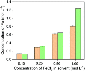 | ||
| Fig. 6 Concentration of Fe(II) (orange bars) and total Fe (green bars) in the leachates obtained from leaching of chalcopyrite with different initial FeCl3 concentration in the leaching agent. | ||
A similar analysis was performed for determination of Cu(I) in EG leachates, but 2,9-dimethyl-1,10-phenanthroline (neocuproine) was used as chelating colorometric agent for Cu(I) (Scheme 2).45
The formed complex has an absorption maximum at 456 nm in acidic solutions with pH 4–7 (see Fig. S2†). It was confirmed by UV-Vis absorption spectroscopy that neocuproine does not complex with other ions, such as Fe(II), Fe(III) and Cu(II) (see Fig. S2†). The same leachates were used for Cu(I) determination as that for Fe(II) determination. Fig. 7 shows that the amount of Cu(I) determined via UV-Vis absorption spectroscopy was the same as that of the amount of copper determined with ICP-OES. The slight difference between two methods is likely due to an analytical error. Thus, all the copper produced by leaching of chalcopyrite was in the form of Cu(I). Based on the fact that 3 mol of FeCl3 is required to quantitatively leach 1 mol of chalcopyrite (CuFeS2) to the leachate in the form of Fe(II) and Cu(I), the theoretical maximum Cu contents in the leachate could be calculated with different initial FeCl3 concentrations, shown as purple bars in Fig. 7. It is clearly seen that the molar efficiency of the reaction reached the highest (87%) when the concentration of FeCl3 in the leaching agent is 0.50 mol L−1.
The mineralogical compositions of chalcopyrite and the solid residue after leaching were studied by powder XRD. The X-ray diffractogram of chalcopyrite showed that in the chalcopyrite mineral sample the main component was CuFeS2 with some quartz gangue materials (Fig. 8). After leaching, the diffraction peaks of CuFeS2 diminished and new peaks of elemental sulfur appeared, indicating the leaching product of sulfidic ions was solid elemental sulfur. The sulfur in the leachate was analyzed with ICP-OES, but it was found to be below the detected limit, which indicates that an negligible amount of sulfur was further oxidized to sulfate and turned into a soluble form. From the above UV-Vis absorption measurements and characterization by XRD, it can be concluded that the leaching mechanism of chalcopyrite in FeCl3–EG solutions is:
| CuFeS2 + 3FeCl3 → 4FeCl2 + CuCl + 2S | (2) |
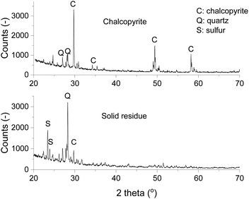 | ||
| Fig. 8 X-ray diffractograms of chalcopyrite (top) and the solid residue (bottom) after leaching at 90 °C and 800 rpm for 24 h with 0.5 mol L−1 of FeCl3 in ethylene glycol. | ||
The fact that the oxidation product is elemental solid sulfur instead of sulfate ions (in the form of sulfuric acid) makes the process greener, because the sulfur can be easily collected, whereas the sulfuric acid needs to be neutralized with base before discarding to the waste water stream.
Leaching kinetics
The kinetics of chalcopyrite leaching in solvometallurgy were assessed on the basis of the shrinking-sphere model, because it was observed that the particles got smaller after leaching. Since temperature had a major influence on the leaching rate, it was considered that the leaching process was controlled by surface chemical reaction. The dissolution of copper was fitted with linear kinetics according to eqn (3):| kct = 1 − (1 − X)1/3 | (3) |
 | (4) |
![[thin space (1/6-em)]](https://www.rsc.org/images/entities/char_2009.gif) kcversus 1/T allows for the apparent activation energy to be calculated (Fig. S4†). The calculated Ea was 60.1 kJ mol−1. This value is in the same range as those reported for hydrometallurgical leaching of chalcopyrite.47 The linear fitting confirms that the copper leaching in our solvometallurgical process is indeed controlled by the surface chemical reaction.
kcversus 1/T allows for the apparent activation energy to be calculated (Fig. S4†). The calculated Ea was 60.1 kJ mol−1. This value is in the same range as those reported for hydrometallurgical leaching of chalcopyrite.47 The linear fitting confirms that the copper leaching in our solvometallurgical process is indeed controlled by the surface chemical reaction.
Electrodeposition of copper
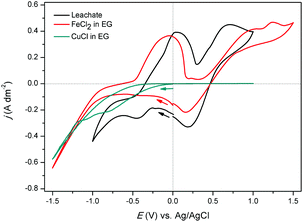
Electrodeposition of copper was studied from both aqueous solutions and ionic liquids.48–52 In this section, the feasibility of electrodeposition of copper from ethylene glycol solutions (the pregnant leachate) was investigated. CVs (second cycle) of the synthetic solutions of 0.68 mol L−1 of FeCl2 in EG, of 0.17 mol L−1 of CuCl in EG, and of the real pregnant leachate containing 0.68 mol L−1 of FeCl2 and 0.15 mol L−1 of CuCl in EG are shown in Fig. 9. The measurements were performed at room temperature at a scan rate of 10 mV s−1 with the reference electrode Ag/AgCl. The CV of the synthetic FeCl2 solution shows several cathodic and anodic current peaks or waves at various potentials. In the forward scan, the increase in cathodic current at −0.70 V vs. Ag/AgCl is ascribed to the reduction of iron(II) to iron(0). In the backward scan, the anodic current wave at −0.50 V vs. Ag/AgCl is ascribed to the stripping of deposited iron to iron(II). The successive current increase, initiating at +0.30 V vs. Ag/AgCl is attributed to oxidation of iron(II) to iron(III). Furthermore, after passing the vertex potential of +1.50 V vs. Ag/AgCl, a cathodic peak is observed, and attributed to reduction of the formed iron(III) to iron(II). The observed electrochemical behavior of FeCl2 in EG is in good agreement to that described by Panzeri et al.53 The CV of the synthetic CuCl solution only shows one distinct feature; a cathodic current increase at 0.00 V vs. Ag/AgCl in the forward scan. The corresponding process is the reduction of copper(I) to copper. Notably, electrodeposition of copper from the prepared ethylene glycol solution is irreversible, as no stripping peak is observed. In the CV of the leachate, in the forward scan, the increase in cathodic current at −0.48 V vs. Ag/AgCl and the cathodic current wave, initiating at approximately −0.70 V vs. Ag/AgCl are ascribed to the reduction of copper(I) species to copper(0) and the reduction of iron(II) species to iron(0), respectively. The anodic peak in the backward scan, initiating at −0.30 V vs. Ag/AgCl likely involves stripping of deposited iron to iron(II), whereas the anodic peak and +0.30 V vs. Ag/AgCl may be ascribed to the further oxidation of iron(II) to iron(III). The subsequent cathodic peak current at +0.75 V vs. Ag/AgCl may be ascribed to reduction of iron(III) to iron(II). Assignment of these cathodic and anodic features to their corresponding reduction and oxidation processes was done on the basis of CVs of the synthetic solutions.A deposition experiment was performed at potential of −0.30 V vs. Ag/AgCl for 2 hours. At this potential, copper(I) reduction is under kinetic control. The solution was stirred, attaining a diffusion layer with constant thickness, therefore counteracting depletion of copper(I) species in the vicinity of the electrode. The deposit exhibits a distinct copper color (Fig. S5†). The morphology and elemental composition of the deposit were analyzed using SEM-EDS. The SEM images in Fig. 10 show uniform cubic crystalline deposits, fully covering the surface of the platinum substrate. The EDS spectrum in Fig. S6† indicates that the deposits comprise fully of copper. Very small peaks of C, O, Cl and Fe are detected, which are attributed to residual leachate, present on the deposit. It can be concluded that electrodeposition of copper directly from organic ethylene glycol solutions is feasible and the impure iron deposit can be completely avoided.
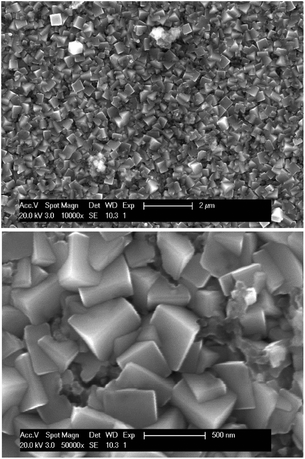 | ||
| Fig. 10 SEM images of copper deposits obtained by applying −0.30 V vs. Ag/AgCl for 2 hours at room temperature. The applied accelerating voltage equaled 20 kV. | ||
The faradaic efficiency of the Cu electrodeposition is 37%. As the applied overpotential is within the electrochemical window of EG, and the obtained deposits are comprised of pure copper, the second occurring process, consuming approximately 63% of the charge, is assumed to be the reduction of iron(III) to iron(II). This iron(III) may originate from two different “sources”. After leaching, a small amount of unreacted iron(III) is likely present in the solution. Furthermore, it might be possible that iron(III), presumably formed at the anode as the counter electrode reaction (Fe(II) oxidation to Fe(III)), migrates through the anion-exchange membrane towards the cathode. Hence, to increase the faradaic efficiency, it is necessary to make sure that no Fe(III) can be reduced at the working electrode. Removal of all unreacted iron(III) and selection of a by iron(III) impermeable membrane is required.
Conceptual process flow sheet
A conceptual closed-loop process for the extraction of copper from chalcopyrite is proposed (Fig. 11). As the above experimental results have shown, copper and iron in chalcopyrite can be extracted quantitatively with the lixiviant FeCl3–EG and sulfur can be removed as solid elemental sulfur. The metallic copper can be produced by direct electrodeposition from the pregnant leachate without any other competing electrochemical reactions. Meanwhile, Fe(III) can be regenerated for reusing in the next cycle by oxidizing the Fe(II) in the anode. However, due to the fact that the concentration of Fe(II) is higher than Cu(I) in the pregnant leachate, not all Fe(II) can be oxidized when all Cu(I) was reduced to Cu(0). Thus the Fe(II) in the Cu-depleted leachate needs to be removed before the recycling of FeCl3–EG solutions. This can be achieved by solvent extraction since Fe(II) and Fe(III) have very different complexing behavior.54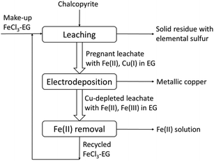 | ||
| Fig. 11 Conceptual closed-loop solvometallurgical process flow sheet for the extraction of copper from chalcopyrite with FeCl3 in ethylene glycol solutions. | ||
The designed solvometallurgical process is green as it is in line with the principles of green chemistry. The process is atom economic, as the reaction efficiency of FeCl3 with chalcopyrite can reach 87%, which can be even higher after optimization of the process. Ethylene glycol instead of the corrosive acidic aqueous solutions in hydrometallurgical processes is employed and it is a recommended green solvent according to the CHEM21 selection guide and the Global Harmonized System (GHS), which ensures the greenness of our process.43 It is safer and the potential for explosion is low, because the leaching can be operated at atmospheric pressure even at above 100 °C due to the high boiling point of the solvent, whereas in hydrometallurgical process at temperatures above 100 °C, it is often operated at high pressure and autoclave is required. Moreover, the closed-loop process can prevent waste or at least minimize the amount of the waste, and the regeneration of the oxidizing agent FeCl3 while electrodepositing of Cu can ensure the sustainability of our developed process. The fast and efficient leaching, direct production of metallic copper and simultaneous regeneration the oxidizing agent FeCl3, make up a sustainable closed-loop solvometallurgical process, which could represent a key step forward towards greenness of copper metallurgy.
Conclusions
The developed closed-loop solvometallurgical process could effectively extract copper from different copper sulfidic minerals, with FeCl3 in ethylene glycol used as lixiviant at elevated temperature and at atmospheric pressure. Unlike the hydrometallurgical process, no passivation layer was formed in our solvometallurgical process, which ensures the quantitative extraction of copper in relatively short time. The mechanistic study of leaching confirmed that the leaching products were ferrous chloride, cuprous chloride and solid elemental sulfur. The production of elemental sulfur instead of sulfuric acid makes the downstream processing easier and can avoid the acid drainage problem. Copper can be directly electrodeposited from the pregnant leachate without the contamination of iron. This simplifies the process and minimizes the operation steps. The regeneration of FeCl3 during the electrochemical process ensures the sustainability of the developed process. The closed-loop solvometallurgical process is a key step forward towards a greener process of copper-bearing ore minerals.Conflicts of interest
There are no conflicts to declare.Acknowledgements
The research leading to these results received funding from the European Research Council (ERC) under the European Union's Horizon 2020 Research and Innovation Programme: Grant Agreement 694078—Solvometallurgy for critical metals (SOLCRIMET). The research was also funded by a PhD grant of the Research Foundation Flanders (FWO) to W. M. (1SB8319N). The authors also thank Mehmet Ali Recai Önal and Lukas Gijsemans for the pre-treatment of the minerals and for helping with the leaching experiments.Notes and references
- Y. Li, N. Kawashima, J. Li, A. P. Chandra and A. R. Gerson, Adv. Colloid Interface Sci., 2013, 197–198, 1–32 CAS.
- A. A. Baba, K. I. Ayinla, F. A. Adekola, M. K. Ghosh, O. S. Ayanda, R. B. Bale, A. R. Sheik and S. R. Pradhan, Int. J. Min. Eng. Miner. Process., 2012, 1, 1–16 CrossRef.
- T. Moyo, J. Petersen and M. J. Nicol, Hydrometallurgy, 2018, 182, 97–103 CrossRef CAS.
- H. R. Watling, Hydrometallurgy, 2014, 146, 96–110 CrossRef CAS.
- H. R. Watling, Hydrometallurgy, 2013, 140, 163–180 CrossRef CAS.
- G. Yue and E. Asselin, Electrochim. Acta, 2014, 146, 307–321 CrossRef CAS.
- G. Yue, L. Zhao, O. G. Olvera and E. Asselin, Hydrometallurgy, 2014, 147–148, 196–209 CrossRef CAS.
- M. Al-Harahsheh, S. Kingman and A. Al-Harahsheh, Hydrometallurgy, 2008, 91, 89–97 CrossRef CAS.
- M. Lundström, J. Aromaa, O. Forsén, O. Hyvärinen and M. H. Barker, Hydrometallurgy, 2005, 77, 89–95 CrossRef.
- O. Hyvärinen and M. Hämäläinen, Hydrometallurgy, 2005, 77, 61–65 CrossRef.
- M. S. Bafghi, A. H. Emami and A. Zakeri, Metall. Mater. Trans. B, 2013, 44, 1166–1172 CrossRef CAS.
- O. G. Olvera, M. Rebolledo and E. Asselin, Hydrometallurgy, 2016, 165, 148–158 CrossRef CAS.
- D. Dreisinger, Hydrometallurgy, 2006, 83, 10–20 CrossRef CAS.
- S. J. Petrovic, G. D. Bogdanovic and M. M. Antonijevic, Trans. Nonferrous Met. Soc. China, 2018, 28, 1444–1455 CrossRef CAS.
- M. D. Turan, H. Arslanoglu and H. S. Altundogan, J. Taiwan Inst. Chem. Eng., 2015, 50, 49–55 CrossRef CAS.
- R. K. Garlapalli, E. H. Cho and R. Y. K. Yang, Metall. Mater. Trans. B, 2010, 41, 308–317 CrossRef.
- F. R. Carrillo-Pedroza, M. A. Sanchez-Castillo, M. J. Soria-Aguilar, A. Martinez-Luevanos and E. C. Gutierrez, Can. Metall. Q., 2010, 49, 219–226 CrossRef CAS.
- S. Panda, A. Akcil, N. Pradhan and H. Deveci, Bioresour. Technol., 2015, 196, 694–706 CrossRef CAS PubMed.
- X. Li, A. Van den Bossche, T. Vander Hoogerstraete and K. Binnemans, Chem. Commun., 2018, 54, 475–478 RSC.
- X. Li, Z. Li, M. Orefice and K. Binnemans, ACS Sustainable Chem. Eng., 2019, 7, 2578–2584 CrossRef CAS PubMed.
- N. K. Batchu, T. Vander Hoogerstraete, D. Banerjee and K. Binnemans, Sep. Purif. Technol., 2017, 174, 544–553 CrossRef CAS.
- Z. Li, X. Li, S. Raiguel and K. Binnemans, Sep. Purif. Technol., 2018, 201, 318–326 CrossRef CAS.
- Z. Li, B. Onghena, X. Li, Z. Zhang and K. Binnemans, Ind. Eng. Chem. Res., 2019, 58, 15628–15636 CrossRef CAS PubMed.
- Z. Li, Z. Zhang, S. Smolders, X. Li, S. Raiguel, E. Nies, D. E. De Vos and K. Binnemans, Chem. – Eur. J., 2019, 25, 9197–9201 CrossRef CAS PubMed.
- C. Deferm, J. C. Malaquias, B. Onghena, D. Banerjee, J. Luyten, H. Oosterhof, J. Fransaer and K. Binnemans, Green Chem., 2019, 21, 1517–1530 RSC.
- A. P. Abbott, G. Frisch, S. J. Gurman, A. R. Hillman, J. Hartley, F. Holyoak and K. S. Ryder, Chem. Commun., 2011, 47, 10031–10033 RSC.
- A. P. Abbott, G. Frisch, J. Hartley and K. S. Ryder, Green Chem., 2011, 13, 471–481 RSC.
- A. P. Abbott, R. C. Harris, F. Holyoak, G. Frisch, J. Hartley and G. R. T. Jenkin, Green Chem., 2015, 17, 2172–2179 RSC.
- G. R. T. Jenkin, A. Z. M. Al-Bassam, R. C. Harris, A. P. Abbott, D. J. Smith, D. A. Holwell, R. J. Chapman and C. J. Stanley, Miner. Eng., 2016, 87, 18–24 CrossRef CAS.
- A. P. Abbott, A. Z. M. Al-Bassam, A. Goddard, R. C. Harris, G. R. T. Jenkin, F. J. Nisbet and M. Wieland, Green Chem., 2017, 19, 2225–2233 RSC.
- J. A. Whitehead, G. A. Lawrance and A. McCluskey, Green Chem., 2004, 6, 313–315 RSC.
- C. Carlesi, E. Cortes, G. Dibernardi, J. Morales and E. Muñoz, Hydrometallurgy, 2016, 161, 29–33 CrossRef CAS.
- O. Kuzmina, E. Symianakis, D. Godfrey, T. Albrecht and T. Welton, Phys. Chem. Chem. Phys., 2017, 19, 21556–21564 RSC.
- T. Dong, Y. Hua, Q. Zhang and D. Zhou, Hydrometallurgy, 2009, 99, 33–38 CrossRef CAS.
- A. Al-Zubeidi, D. Godfrey and T. Albrecht, J. Electroanal. Chem., 2018, 819, 130–135 CrossRef CAS.
- D. Godfrey, J. H. Bannock, O. Kuzmina, T. Welton and T. Albrecht, Green Chem., 2016, 18, 1930–1937 RSC.
- O. J. Solis-Marcial and G. T. Lapidus, Hydrometallurgy, 2013, 131, 120–126 CrossRef.
- O. J. Solis-Marcial and G. T. Lapidus, Hydrometallurgy, 2014, 147, 54–58 CrossRef.
- A. Ruiz-Sanchez and G. T. Lapidus, Hydrometallurgy, 2017, 169, 192–200 CrossRef CAS.
- O. J. Solis-Marcial and G. T. Lapidus, Electrochim. Acta, 2014, 140, 434–437 CrossRef CAS.
- J. Ahn, J. Wu and J. Lee, Hydrometallurgy, 2019, 187, 54–62 CrossRef CAS.
- T. Hidalgo, L. Kuhar, A. Beinlich and A. Putnis, Hydrometallurgy, 2019, 188, 140–156 CrossRef CAS.
- D. Prat, A. Wells, J. Hayler, H. Sneddon, C. R. McElroy, S. Abou-Shehada and P. J. Dunn, Green Chem., 2016, 18, 288–296 RSC.
- R. De Clercq, M. Dusselier and B. F. Sels, Green Chem., 2017, 19, 5012–5040 RSC.
- A. A. Gouda and A. S. Amin, Arabian J. Chem., 2010, 3, 159–165 CrossRef CAS.
- E. Agustina, J. Goak, S. Lee, Y. Seo, J. Y. Park and N. Lee, ChemistryOpen, 2015, 4, 613–619 CrossRef CAS PubMed.
- T. Hidalgo, L. Kuhar, A. Beinlich and A. Putnis, Miner. Eng., 2018, 125, 66–74 CrossRef CAS.
- T. Zapryanova, N. Jordanov and A. Milchev, J. Electroanal. Chem., 2008, 612, 47–52 CrossRef CAS.
- S. Z. El Abedin, M. Polleth, S. A. Meiss, J. Janek and F. Endres, Green Chem., 2007, 9, 549–553 RSC.
- J. Casaban, C. Hardacre, S. L. James and M. C. Lagunas, Green Chem., 2012, 14, 1643–1648 RSC.
- N. R. Brooks, S. Schaltin, K. Van Hecke, L. Van Meervelt, K. Binnemans and J. Fransaer, Chem. – Eur. J., 2011, 17, 5054–5059 CrossRef CAS PubMed.
- S. Schaltin, L. D'Urzo, Q. Zhao, A. Vantomme, H. Plank, G. Kothleitner, C. Gspan, K. Binnemans and J. Fransaer, Phys. Chem. Chem. Phys., 2012, 14, 13624–13629 RSC.
- G. Panzeri, A. Accogli, E. Gibertini, C. Rinaldi, L. Nobili and L. Magagnin, Electrochim. Acta, 2018, 271, 576–581 CrossRef CAS.
- E. J. Kim, Y. S. Kim and J. M. Choi, Bull. Korean Chem. Soc., 2008, 29, 99–103 CrossRef CAS.
Footnote |
| † Electronic supplementary information (ESI) available: UV-Vis absorption spectra of the pregnant leachate for quantification of Fe(II) and Cu(I); fitted linear curves for determination of the apparent rate constant and activation energy; pictures of copper deposit and EDX analysis results; parameters for microwave digestion of copper sulfidic ores. See DOI: 10.1039/c9gc02983d |
| This journal is © The Royal Society of Chemistry 2020 |

