 Open Access Article
 This Open Access Article is licensed under a
 Creative Commons Attribution 3.0 Unported Licence
Can 3D electron diffraction provide accurate atomic structures of metal–organic frameworks?†
Zhehao
Huang
 *a,
Meng
Ge
a,
Francesco
Carraro
b,
Christian
Doonan
c,
Paolo
Falcaro
b and
Xiaodong
Zou
*a
*a,
Meng
Ge
a,
Francesco
Carraro
b,
Christian
Doonan
c,
Paolo
Falcaro
b and
Xiaodong
Zou
*a
aDepartment of Materials and Environmental Chemistry, Stockholm University, 10691 Stockholm, Sweden. E-mail: zhehao.huang@mmk.su.se; xzou@mmk.su.se
bInstitute of Physical and Theoretical Chemistry, Graz University of Technology, Stremayrgasse 9, 8010 Graz, Austria
cDepartment of Chemistry and the Centre for Advanced Nanomaterials, The University of Adelaide, Adelaide, 5005 South Australia, Australia
First published on 12th March 2020
Abstract
Many framework materials such as metal–organic frameworks (MOFs) or porous coordination polymers (PCPs) are synthesized as polycrystalline powders, which are too small for structure determination by single crystal X-ray diffraction (SCXRD). Here, we show that a three-dimensional (3D) electron diffraction method, namely continuous rotation electron diffraction (cRED), can be used for ab initio structure determination of such materials. As an example, we present the complete structural analysis of a biocomposite, denoted BSA@ZIF-CO3-1, in which Bovine Serum Albumin (BSA) was encapsulated in a zeolitic imidazolate framework (ZIF). Low electron dose was combined with ultrafast cRED data collection to minimize electron beam damage to the sample. We demonstrate that the atomic structure obtained by cRED is as reliable and accurate as that obtained by single crystal X-ray diffraction. The high accuracy and fast data collection open new opportunities for investigation of cooperative phenomena in framework structures at the atomic level.
Introduction
Metal–organic frameworks (MOFs) or porous coordination polymers (PCPs) offer large surface areas, tuneable pore structures, adjustable chemical functionality and structural flexibility.1,2 Because of these unique structural properties, they have tremendous potential in a wide range of applications such as catalysis, gas storage and separation, ion exchange, bio-medical and bio-technological applications.3–9 Notably, under different synthesis conditions, various MOF structures with different topologies and pore sizes can be obtained using the same metal ions and organic linkers. In many cases, MOFs undergo several stages of structural transformations during the synthesis. For example, a combination of 2-methylimidazole (HmIM) and Zn(II) cations could produce zeolitic imidazolate frameworks (ZIFs) with different topologies, such as sodalite (sod), diamondoid (dia), katsenite (kat), and a layered ZIF-L.10–13 In addition, many MOFs are flexible and undergo structural changes when they interact with other species, known by the breathing and swelling phenomena associated with host–guest interactions.14–18 Structural changes can also be triggered by other external stimuli, such as photochemical, thermal, and mechanical changes.19–22 One the other hand, many MOF frameworks are rigid, and incorporation of guest species or defects in MOF structures does not necessarily involve crystallographic structural changes.23–28 In all cases, it is essential to know the exact arrangement of atoms in the material in order to understand the properties and functionalities of the material as well as the host–guest interactions. Therefore, ab initio structure determination of the material is crucial.Single crystal X-ray diffraction (SCXRD) is the most powerful method for structure determination of crystalline materials, including MOFs.29–31 However, structure determination by SCXRD requires large (>5 μm) and well-ordered crystals, which are sometimes difficult to synthesize. Furthermore, experiments for studying cooperative phenomena may also destroy the crystallinity of the MOFs. As a consequence, many nano- and micron-sized MOFs have generally been discarded because of the difficulties in their structure determination. Thus, methods that can facilitate structure determination from polycrystalline powders would be of great importance for the development of new MOF materials and studies of cooperative phenomena. Although powder X-ray diffraction (PXRD) can be an alternative method for studying polycrystalline MOFs, ab initio structure determination by PXRD is still very challenging, especially when diffraction peaks overlap and samples contain multiple phases. The peak overlap becomes more severe for structures with large unit cell parameters and crystals with small sizes and containing defects.
Single crystal electron diffraction can be obtained from crystals that are too small to be studied by SCXRD. Although ab initio structure analysis by using electron diffraction was demonstrated earlier,32–34 a major revolution occurred during the past decade by the development of new 3D electron diffraction methods.35,36 Several groups independently developed 3D single crystal electron diffraction methods and software for semi-automatic data collection on standard TEMs. These include rotation electron diffraction (RED) by combining step-wise fine beam tilt and coarse crystal rotation,36,37 electron diffraction tomography by step-wise crystal rotation without or with electron precession (automated diffraction tomography (ADT),35,38 or precession-assisted electron diffraction tomography (PEDT)39), and microcrystal electron diffraction (MicroED) by step-wise crystal rotation.40 Continuous rotation electron diffraction (cRED) was later developed independently by several groups,41–44 and is also known as IEDT42 and MicroED.43
3D electron diffraction (ED) methods have been shown to be powerful for ab initio structure determination of MOFs from nano- and micron-sized crystals.45–51 Because of the strong interactions of electrons with matter, 3D single crystal electron diffraction can be obtained from nanocrystals that are 108 times smaller in volume than those needed for single crystal X-ray diffraction. On the other hand, the strong interaction also leads to multiple scattering of electrons in the crystal, which makes the intensities of reflections dynamical and causes them to deviate from the kinematical intensities. Although it is possible to solve and refine structures using 3D ED data, the discrepancy between the kinematical intensities calculated from the structure model and the dynamical intensities obtained experimentally results in relatively high R-values after the structure refinement (>0.15). It is thus important to compare the structural models obtained by 3D ED with those obtained by SCXRD to know what accuracy structure determination by 3D ED can achieve. Although this has been studied in stable crystals such as zeolites and metal oxides,52,53 it has not yet been applied to MOFs.
Here, we report an ab initio structure determination of a ZIF biocomposite by continuous rotation electron diffraction (cRED). The ZIF biocomposite was synthesized from Zn(OAc)2·2H2O, HmIM and Bovine Serum Albumin (BSA) in water,54 and is denoted as BSA@ZIF-CO3-1. It was considered as a new ZIF phase. The structure was solved and refined using cRED data, and is the same as that of ZIF-CO3-1 (often abbreviated as ZIF-C54) previously determined by SCXRD using synchrotron data.55 The results of structure determination by cRED were compared to those by SCXRD.
Experimental section
Synthesis
BSA@ZIF-CO3-1 was discovered during a study of the phase dependent encapsulation and release of ZIF-based biocomposites.54 In detail, 300 μL of a 440 mM aqueous solution of 2-methylimidazole, HmIM (TCI Chemicals), 60 μL of a 36 mg mL−1 aqueous solution of BSA (lyophilized powder, Sigma-Aldrich) and 1140 μL of deionized water were mixed in a 2 mL plastic centrifuge tube for 1 minute. Then, this solution was added to 500 μL of an 80 mM aqueous solution of Zn(OAc)2·2(H2O) (EMSURE, Merck). The reaction mixture was left under static conditions (no shaking and no stirring) at RT for 24 h. After this reaction time, the biocomposite was isolated via centrifugation (13![[thin space (1/6-em)]](https://www.rsc.org/images/entities/char_2009.gif) 000 rpm for 5 min; centrifuge used: Eppendorf 5425) and the supernatant was discarded. The obtained powder pellet was then re-suspended in deionized water (1.5 mL) using a vortex mixer (3000 rpm, 1 minute, VELP Scientifica ZX3) and the centrifugation step (13000 rpm, 5 min) was repeated. This washing procedure was repeated 6 times using deionized (DI) water. Finally, the recovered powders were air-dried for 48 h at RT. The PXRD pattern is shown in Fig. 1, and does not match any of the known ZIFs built from Zn(II) and 2-methylimidazole. The material was therefore considered to be a new ZIF, and ab initio structure determination by cRED was performed. To test the influence of the CO2 dissolved in the water, we performed the same synthesis under an inert atmosphere with degassed DI water. Both the precursors (Zn acetate, HmIM and BSA) and their concentrations were kept identical to the ones used for the preparation of BSA@ZIF-CO3-1. To degas the water, N2 was bubbled through 50 mL of DI water in a two-necked balloon for 4 hours at room temperature while stirring. The initial pH of the water was 5.7. The acidity of deionized water is associated with the presence of dissolved CO2.56 After 3 hours of degassing, the pH increased to close to 7, supporting the effectiveness of the CO2 removal.56 The degassed water and the balloons used to prepare the precursor solutions were then maintained under an Ar atmosphere. After mixing the Zn2+ and the HmIM–BSA solutions, the mixture was kept under Ar for 24 h and then the product was washed using degassed DI water.
000 rpm for 5 min; centrifuge used: Eppendorf 5425) and the supernatant was discarded. The obtained powder pellet was then re-suspended in deionized water (1.5 mL) using a vortex mixer (3000 rpm, 1 minute, VELP Scientifica ZX3) and the centrifugation step (13000 rpm, 5 min) was repeated. This washing procedure was repeated 6 times using deionized (DI) water. Finally, the recovered powders were air-dried for 48 h at RT. The PXRD pattern is shown in Fig. 1, and does not match any of the known ZIFs built from Zn(II) and 2-methylimidazole. The material was therefore considered to be a new ZIF, and ab initio structure determination by cRED was performed. To test the influence of the CO2 dissolved in the water, we performed the same synthesis under an inert atmosphere with degassed DI water. Both the precursors (Zn acetate, HmIM and BSA) and their concentrations were kept identical to the ones used for the preparation of BSA@ZIF-CO3-1. To degas the water, N2 was bubbled through 50 mL of DI water in a two-necked balloon for 4 hours at room temperature while stirring. The initial pH of the water was 5.7. The acidity of deionized water is associated with the presence of dissolved CO2.56 After 3 hours of degassing, the pH increased to close to 7, supporting the effectiveness of the CO2 removal.56 The degassed water and the balloons used to prepare the precursor solutions were then maintained under an Ar atmosphere. After mixing the Zn2+ and the HmIM–BSA solutions, the mixture was kept under Ar for 24 h and then the product was washed using degassed DI water.
 | ||
| Fig. 1 The PXRD pattern (λ = 1.5418 Å) of BSA@ZIF-CO3-1. | ||
TEM and cRED data collection
Samples for TEM investigations were dispersed in water. A droplet of the suspension was transferred onto a carbon-coated copper grid. TEM images and cRED data were collected on a JEOL JEM2100 microscope operated at 200 kV (Cs 1.0 mm, point resolution 0.23 nm). TEM images were recorded with a Gatan Orius 833 CCD camera (resolution 2048 × 2048 pixels, pixel size 7.4 μm). cRED data collection was controlled by using the data acquisition software Instamatic,41,57 and the electron diffraction (ED) frames were recorded with a Timepix QTPX-262k hybrid detector (512 × 512 pixels, pixel size 55 μm, max. 120 frames per second, Amsterdam Sci. Ins.) A single-tilt tomography holder, which could tilt from −70° to +70° in the TEM, was used for the data collection. The area used for cRED data collection was about 1.0 μm in diameter, as defined by a selected area aperture. To minimize electron beam damage to the crystal and maximize the data quality, a low electron dose and high rotation speed were applied. The goniometer rotation speed was 0.45° per second and the exposure time was 0.5 s per frame. A typical cRED dataset covered a crystal rotation angle of 103.3° and took 3.8 min to collect. cRED datasets were collected from several crystals.Results and discussion
Continuous rotation electron diffraction data collection
Different from the step-wise data collection in ADT/PEDT and RED where no crystal rotation is applied during the exposure, the crystal is rotated continuously at a constant speed during the cRED data collection (Fig. 2).53 The time needed to collect a dataset is determined by the total rotation range and the rotation speed of the crystal. By using the Timepix hybrid detector, a complete cRED dataset could be collected in less than one minute, with an electron dose rate of <0.1 e Å−2 s−1. This development is crucial for studies of electron beam-sensitive materials, e.g. MOFs, COFs, ZIFs, etc. In order to track the crystal movement and keep the crystal in the beam during the continuous rotation, we developed manual41 and automated58 crystal tracking by defocusing ED frames at given intervals during crystal rotation, which are implemented in the software Instamatic.57 In this way, re-centering of crystals can be achieved without stopping the crystal rotation. By taking advantage of the cRED method, the quality of datasets and the accuracy of structure determination are improved, and thereby more detailed structural information can be revealed.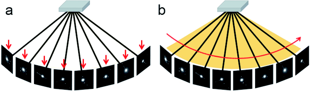 | ||
| Fig. 2 Illustration of step-wise and continuous rotation methods. (a) The step-wise rotation methods collect each ED frame at a certain angle. The advantage is that it is possible to track the crystal and perform re-centering and height adjustment. (b) The continuous rotation methods collect ED frames continuously. The advantages are that integrated diffraction intensities can be obtained and data collection is much faster than that for step-wise rotation. | ||
3D electron diffraction data are collected at arbitrary orientations of a crystal, and most of the ED frames are off the zone axes which largely minimizes the chance of multiple scattering in the crystal.34,59 The RED data processing program can process 3D electron diffraction data collected by both step-wise and continuous rotation methods, and can reconstruct the 3D reciprocal lattice (Fig. 3) from which the unit cell parameters and space group can be determined.37 Because cRED data collection resembles SCXRD data collection, existing software for data processing developed for SCXRD can be directly used. Many X-ray crystallographic software packages, such as XDS,60,61 DIALS,62,63 and MOSFLM64 have been adapted to integrate and extract intensity information from cRED data. The intensities are subsequently treated as kinematical input for ab initio structure solution via direct methods, charge flipping, etc.
 | ||
| Fig. 3 The graphical user interface of the RED data processing program. It shows the reconstructed 3D reciprocal lattice for a zeolite, obtained from 1472 individual ED frames. The hk0, hk1 and hk−1 layers are marked in green, red and blue, respectively.37 Copyright, International Union of Crystallography. | ||
cRED data processing and structure determination of BSA@ZIF-CO3-1
We applied cRED to determine the structure of BSA@ZIF-CO3-1. The first step was to determine the unit cell parameters and space group. The 3D reciprocal lattice was reconstructed from the cRED data by the RED data processing program37 and is shown in Fig. 4. All diffraction spots can be indexed by a single primitive lattice, confirming the single crystal nature of the BSA@ZIF-CO3-1 biocomposite. The unit cell parameters were determined to be a = 10.31 Å, b = 12.51 Å, c = 4.65 Å, α = 88.8°, β = 89.5°, γ = 89.6°. The intensity distribution of reflections in the 3D reciprocal lattice indicates that the crystal is orthorhombic with Laue class mmm (Fig. 4). The unit cell angles α, β, and γ are close to 90°, which also confirms the orthorhombic crystal system. The reflection conditions can be deduced from the two-dimensional (2D) slices cut at the hk0, 0kl, and h0l planes; 0kl: k = 2n; h0l: h = 2n; h00: h = 2n; 0k0: k = 2n, which correspond to two possible space groups: Pba2 (no. 32), and Pbam (no. 55). A broad sphere is observed in addition to the sharp diffraction spots, presumably due to the contribution of the BSA molecules. This indicates that BSA molecules are encapsulated in the ZIF crystal. | ||
| Fig. 4 (a–c) 2D slices cut from the reconstructed 3D reciprocal lattice of BSA@ZIF-CO3-1 showing the (a) hk0, (b) 0kl, and (c) h0l planes. The reflection conditions can be deduced to be 0kl: k = 2n; h0l: h = 2n; h00, h = 2n; 0k0: k = 2n. (d) 3D reciprocal lattice of BSA@ZIF-CO3-1. All diffraction spots can be indexed by a single lattice, indicating the single crystal nature. A broad ring is observed in all ED patterns, which probably comes from the encapsulated BSA molecules. | ||
The cRED dataset of BSA@ZIF-CO3-1 was further processed by using the XDS package,60,61 with which the unit cell parameters were refined and the intensities of reflections were integrated. The cRED data reached a resolution of 1.00 Å and a completeness of 79.7%, which is sufficient for ab initio structure solution by direct methods. The framework structure of BSA@ZIF-CO3-1 was solved by direct methods using the program SHELXT-2014 (ref. 65 and 66) and atomic scattering factors of electrons. Both space groups, Pba2 and Pbam, were tested. While many atoms were too close to each other in the structure solution using Pbam, the structure determined using Pba2 was reasonable. The positions of all non-H atoms, including Zn, C, N and O, could be found directly. The assignment of the atom types was done according to chemical knowledge.
A good structure refinement requires high data completeness (>90%). In order to increase the data completeness, two cRED datasets from crystals with different initial orientations were merged. The merged data reached a completeness of 94.5%. During the merging step, it is important to ensure that the intensities of common reflections between the datasets have a high similarity. This is assessed via correlation coefficients CC1/2 of the common reflections between the datasets.67 Due to the increased number of reflections after data merging, the Rint value increased from 0.174 to 0.280. The final refinement was done by using SHELXL-2014, and converged to R1 = 0.156. The details of data collection and structure refinement are summarized in Table 1. The crystallographic information file (CIF) is deposited in the Cambridge Structural Database (CSD) with the CCDC code 1979160.†
| cRED data | Synchrotron SCXRD data55 | |
|---|---|---|
| No. datasets merged | 2 | 1 |
| Wavelength (Å) | 0.02508 Å | 0.68890 Å |
| Crystal size (μm3) | 0.5 × 0.5 × 0.3 | 40 × 13 × 7 |
| Resolution (Å) | 1.00 | 0.79 |
| Crystal system | Orthorhombic | Orthorhombic |
| Space group | Pba2 (no. 32) | Pba2 (no. 32) |
| Unit cell a, b, c (Å) | 10.510(2), 12.234(2), 4.6660(9) | 10.536(9), 12.314(10), 4.659(4) |
| Volume (Å3) | 600.0(2) | 604.5(8) |
| Completeness (%) | 94.5 | 98.3 |
| No. reflections in cRED | 1638 | 4239 |
| No. unique reflections | 575 | 1169 |
| No. observed reflections (I > 2 sigma(I)) | 320 | 1040 |
| R 1 (I > 2 sigma(I)) | 0.156 | 0.043 |
| R 1 (all reflections) | 0.225 | 0.049 |
| Goof | 1.272 | 1.022 |
The structure of BSA@ZIF-CO3-1 is shown in Fig. 5. In addition to Zn(II) cations and mIM ions, carbonate ions CO32− are also found in the structure, which is evident from the FTIR and Raman spectra as well.54 The structure is the same as that of ZIF-CO3-1 previously determined by SCXRD.55 ZIF-CO3-1 was previously synthesized from Zn(NO3)2·6H2O and HmIM in the presence of CO2, which was either introduced as CO2 gas or generated in situ via hydrolysis of N,N-dimethylformamide (DMF). The CO2 was incorporated in the framework as a carbonate ion. The captured CO2 can be selectively released by acidifying the ZIF material. The ZIF-CO3-1 framework can be regenerated in water on exposure to CO2.55 In our synthesis, neither CO2 gas nor DMF was used. The incorporated carbonate was presumably derived from the CO2 dissolved in the deionized water.56,68 To support this hypothesis, we performed the synthesis of the biocomposite under an inert atmosphere with degassed water. Under these conditions, no BSA@ZIF-CO3-1 was obtained. Instead, a mainly amorphous product with a minor sod ZIF-8 phase was found.
 | ||
| Fig. 5 The structural model of BSA@ZIF-CO3-1 viewed along (a) the c-axis, and (b) the a-axis. Blue spheres: N; red spheres: O; gray spheres: C; cyan spheres: Zn atoms. | ||
The asymmetric unit consists of one Zn(II) cation, one mIM, and half of a carbonate ion. Each Zn(II) cation binds to two mIM ions to form a chain along the b-axis (Fig. 5b). The chains are further connected by the carbonates to form a 3D framework (Fig. 5). The three oxygen atoms from each carbonate bind to four Zn(II) cations from four different chains (Fig. 5a). They play a crucial role in the formation of the 3D ZIF framework. As expected, the encapsulated BSA molecules are not ordered and cannot be located by cRED. However, it is interesting to compare the structural model with that of ZIF-CO3-1 determined by SCXRD, and see whether the encapsulation of proteins affects the atomic structure.
Comparison of refinement results and structural models obtained by cRED and SCXRD
Electron diffraction suffers from multiple scattering which makes the intensities of reflections dynamical. However, in structure determination by cRED using software developed for SCXRD, the intensities are treated as kinematical. As a result, structure refinements against cRED data often lead to relatively high R1 values compared with those refined against SCXRD data. In addition, the electron optics of the TEM and errors in goniometer rotation as well as the sample height may introduce geometrical distortions in the cRED data, which affect the unit cell determination. It is therefore important to compare the unit cell parameters, the results of crystallographic structure refinement and finally the structural models obtained by cRED and SCXRD.55 These comparisons are given in Fig. 6 and Tables 1–3. | ||
| Fig. 6 Comparison between the structural model of BSA@ZIF-CO3-1 refined from cRED data and that of ZIF-CO3-1 from SCXRD data. (a) The structures are stacked together, viewed along the c-axis. (b) An enlarged figure showing the mIM linker and Zn(II) cations, illustrating the accuracy of the model obtained from the cRED data. Blue spheres: N; red spheres: O; gray spheres: C; cyan spheres: Zn atoms. | ||
One of the obvious advantages of cRED is that only very small crystals are required. As shown in Table 1, the crystals of BSA@ZIF-CO3-1 examined by cRED were 0.5 × 0.5 × 0.3 μm3 in size, which is ca. 50000 times smaller than the crystal of ZIF-CO3-1 (40 × 13 × 7 μm3 in size) studied by SCXRD using a synchrotron source.55 The resolution of the cRED data is 1.00 Å, lower than that of the SCXRD data (0.79 Å). The lower resolution of the cRED data was not caused by beam damage, but by the lower crystallinity of BSA@ZIF-CO3-1, as also shown in its PXRD pattern (Fig. 1). The lower crystallinity is probably caused by the encapsulation of the BSA molecules.
The combined cRED dataset has a data completeness of 94.5% with 575 unique reflections, while the SCXRD dataset has a completeness of 98.3% with 1169 unique reflections. The unit cell parameters obtained by cRED are very close to those determined by SCXRD, and only differ by 0.03(1) (0.3%), 0.08(1) (0.6%) and 0.007(5) (0.2%) Å for a, b and c, respectively. This shows that the unit cell parameters obtained by cRED can be as accurate as those obtained by SCXRD, and the encapsulation of BSA did not change the unit cell parameters.
Even though the R1 value for the structure refinement of BSA@ZIF-CO3-1 against the cRED data (0.225) is much higher compared to that of ZIF-CO3-1 against SCXRD data (0.049), the two structural models are very similar, as shown in Fig. 6 and Table 2. The position of the heavy Zn atom deviates by 0.06(1) Å, while the positions of the light N, C, and O atoms deviate by 0.07(3) Å on average. The C7, O1 and O2 positions corresponding to the carbonate differ on average by 0.03(2) Å for the two models. The largest deviation of 0.13(5) Å occurs for the methyl group (C6). The deviations are comparable to those of more stable materials such as zeolite ZSM-5 (0.07(3) Å with 0.87 Å resolution) and FeSeO3F (0.03(1) Å with 0.78 Å resolution).53 The bond lengths and angles of the two models also show good agreement (Table 3). The average deviation is 0.04(3) Å for the bond lengths and 4(3)° for the bond angles. The anisotropic atomic displacement parameters are also reasonable. This shows that despite the lower crystallinity of BSA@ZIF-CO3-1 and high R1 values, the structural model obtained from cRED data is consistent with that of ZIF-CO3-1 obtained by SCXRD. This suggests that the high R1 values are mainly caused by dynamical effects. The encapsulation of BSA did not alter the framework structure of ZIF-CO3-1.
| Atom | x, y, z coordinates from cRED | x, y, z coordinates from SCXRD | Difference (Å) | ||||
|---|---|---|---|---|---|---|---|
| a The origin of the structural model obtained from cRED data was placed to be the same as that of the model from SCXRD data, using the bridging O2 as a reference. | |||||||
| Zn1 | 0.0453(10) | 0.1357(9) | 0.947(4) | 0.05069(5) | 0.13664(4) | 0.94752(16) | 0.06(1) |
| N2 | −0.089(3) | 0.246(2) | 1.000(7) | −0.0818(5) | 0.2476(4) | 1.0047(10) | 0.08(3) |
| N3 | 0.229(3) | 0.172(2) | 1.039(7) | 0.2299(5) | 0.1726(4) | 1.0227(9) | 0.08(3) |
| C1 | 0.289(3) | 0.259(2) | 0.918(6) | 0.2964(4) | 0.2548(4) | 0.9157(15) | 0.09(3) |
| C4 | 0.309(3) | 0.112(3) | 1.206(9) | 0.3136(7) | 0.1154(5) | 1.1915(16) | 0.09(4) |
| C5 | −0.078(3) | 0.335(2) | 1.169(8) | −0.0715(6) | 0.3372(7) | 1.1814(18) | 0.09(3) |
| C6 | 0.231(5) | 0.341(3) | 0.715(15) | 0.2428(7) | 0.3383(6) | 0.7192(15) | 0.13(5) |
| C7 | 0.0000 | 0.0000 | 1.410(12) | 0.0000 | 0.0000 | 1.4283(17) | 0.09(6) |
| O1 | 0.041(3) | 0.087(3) | 1.531(8) | 0.0396(4) | 0.0847(3) | 1.5444(8) | 0.07(4) |
| O2a | 0.0000 | 0.0000 | 1.140(10) | 0.0000 | 0.0000 | 1.1411(11) | 0.00 |
| Atoms 1,2 | d 1,2 (Å) from cRED | d 1,2 (Å) from SCXRD | Deviation in d 1,2 (Å) |
|---|---|---|---|
| a Symmetry transformations used to generate equivalent atoms: ax, y, −1 + z; b0.5 + x, 0.5 − y, z; c−0.5 + x, 0.5 − y, z; d−x, −y, z. | |||
| Zn1–N2 | 1.97(3) | 1.972(5) | 0.00(3) |
| Zn1–N3 | 2.02(3) | 1.970(5) | 0.05(3) |
| Zn1–O2 | 1.95(2) | 1.982(3) | 0.03(2) |
| Zn1–O1a | 2.03(4) | 1.988(4) | 0.05(4) |
| C1–N3 | 1.36(2) | 1.328(7) | 0.03(2) |
| C1–N2b | 1.34(2) | 1.349(6) | 0.01(2) |
| C4–N3 | 1.36(3) | 1.376(9) | 0.02(3) |
| C5–N2 | 1.35(2) | 1.381(8) | 0.03(2) |
| C4–C5b | 1.36(3) | 1.344(10) | 0.02(3) |
| C1–C6 | 1.51(5) | 1.487(8) | 0.02(5) |
| O1–C7 | 1.28(4) | 1.247(5) | 0.03(4) |
| O2–C7 | 1.26(6) | 1.338(9) | 0.08(6) |
| Average difference in d 1,2 (Å): 0.04(3) | |||
| Atoms 1,2,3 | Angle 1,2,3 (°) from cRED | Angle 1,2,3 (°) from SCXRD | Deviation in angle 1,2,3 (°) |
|---|---|---|---|
| N2–Zn1–N3 | 120.5(12) | 119.9(2) | 1(1) |
| N2–Zn1–O2 | 110.4(12) | 109.63(16) | 0(1) |
| N2–Zn1–O1a | 107.8(15) | 108.00(18) | 0(2) |
| N3–Zn1–O2 | 108.8(10) | 111.60(15) | 3(1) |
| N3–Zn1–O1a | 106.8(15) | 107.26(18) | 0(2) |
| O2–Zn1–O1a | 100.6(15) | 98.11(18) | 3(2) |
| N2b–C1–N3 | 107(3) | 111.7(5) | 5(3) |
| C1c–N2–C5 | 107(3) | 106.0(5) | 1(3) |
| C1–N3–C4 | 112(3) | 105.4(5) | 7(3) |
| N3–C4–C5b | 103(3) | 109.6(6) | 7(3) |
| N2–C5–C4c | 112(3) | 107.3(6) | 5(3) |
| N3–C1–C6 | 126(3) | 123.9(5) | 2(3) |
| N2b–C1–C6 | 127(3) | 124.4(5) | 3(3) |
| O1–C7–O1d | 128(6) | 128.6(7) | 1(6) |
| O1–C7–O2 | 116(3) | 115.7(4) | 0(3) |
| Average difference in angle 1,2,3 (°): 4(3) | |||
Conclusions
Here, we demonstrate the ab initio structure determination of a biocomposite ZIF, BSA@ZIF-CO3-1, by applying continuous rotation electron diffraction (cRED). We also show that the unit cell parameters can be accurately determined using cRED data. This is important for phase analysis and detection of possible structural changes in MOFs. The presence of BSA molecules in the crystal is indicated by a broad sphere in the 3D reciprocal space reconstructed from the cRED data, showing that the molecules are disordered. While it is not possible to locate the BSA molecules, the structure of ZIF-C could be solved and refined using the cRED data. We found that the structural model of ZIF-C obtained from the biocomposite BSA@ZIF-CO3-1 is the same as that of ZIF-CO3-1 obtained by SCXRD. The encapsulation of the BSA in the ZIF does not cause significant changes in the framework structure. We show that despite the high R values originating from multiple scattering, accurate atomic structures can be obtained by cRED. The average deviation between the two models is 0.06(1) Å for Zn(II) and 0.07(3) Å for the light atoms. The combination of fast data collection and accurate structure determination by 3D ED opens new opportunities for studying the dynamical and cooperative structural changes in MOFs and other framework materials.Conflicts of interest
There are no conflicts to declare.Acknowledgements
This work was supported by the Swedish Research Council, with the project No. 2017-04321 (X. Z.) and 2016-04625 (Z. H). P. F. acknowledges TU Graz for the Lead Project (LP-03) and the European Union’s Horizon 2020 Programme (FP/2014-2020)/ERC Grant Agreement No. 771834 – POPCRYSTAL.Notes and references
- O. M. Yaghi, G. Li and H. Li, Nature, 1995, 378(6558), 703–706 CrossRef CAS.
- S. Kitagawa, R. Kitaura and S. Noro, Angew. Chem., Int. Ed., 2004, 43(18), 2334–2375 CrossRef CAS.
- H. Furukawa, K. E. Cordova, M. O’Keeffe and O. M. Yaghi, Science, 2013,(6149), 341 Search PubMed.
- J.-R. Li, J. Sculley and H.-C. Zhou, Chem. Rev., 2012, 112(2), 869–932 CrossRef CAS.
- Y. Cui, B. Li, H. He, W. Zhou, B. Chen and G. Qian, Acc. Chem. Res., 2016, 49(3), 483–493 CrossRef CAS.
- J. Duan, W. Jin and S. Kitagawa, Coord. Chem. Rev., 2017, 332, 48–74 CrossRef CAS.
- N. S. Bobbitt, M. L. Mendonca, A. J. Howarth, T. Islamoglu, J. T. Hupp, O. K. Farha and R. Q. Snurr, Chem. Soc. Rev., 2017, 46(11), 3357–3385 RSC.
- C. Doonan, R. Riccò, K. Liang, D. Bradshaw and P. Falcaro, Acc. Chem. Res., 2017, 50(6), 1423–1432 CrossRef CAS.
- P. Horcajada, R. Gref, T. Baati, P. K. Allan, G. Maurin, P. Couvreur, G. Férey, R. E. Morris and C. Serre, Chem. Rev., 2012, 112(2), 1232–1268 CrossRef CAS.
- K. S. Park, Z. Ni, A. P. Côté, J. Y. Choi, R. Huang, F. J. Uribe-Romo, H. K. Chae, M. O’Keeffe and O. M. Yaghi, Proc. Natl. Acad. Sci. U. S. A., 2006, 103(27), 10186–10191 CrossRef CAS.
- A. D. Katsenis, A. Puškarić, V. Štrukil, C. Mottillo, P. A. Julien, K. Užarević, M.-H. Pham, T.-O. Do, S. A. J. Kimber and P. Lazić, et al. , Nat. Commun., 2015, 6(1), 1–8 Search PubMed.
- Z. Akimbekov, A. D. Katsenis, G. P. Nagabhushana, G. Ayoub, M. Arhangelskis, A. J. Morris, T. Friščić and A. Navrotsky, J. Am. Chem. Soc., 2017, 139(23), 7952–7957 CrossRef CAS.
- R. Chen, J. Yao, Q. Gu, S. Smeets, C. Baerlocher, H. Gu, D. Zhu, W. Morris, O. M. Yaghi and H. Wang, Chem. Commun., 2013, 49(82), 9500–9502 RSC.
- S. Kitagawa and K. Uemura, Chem. Soc. Rev., 2005, 34(2), 109–119 RSC.
- A. Schneemann, V. Bon, I. Schwedler, I. Senkovska, S. Kaskel and R. A. Fischer, Chem. Soc. Rev., 2014, 43(16), 6062–6096 RSC.
- C. Serre, C. Mellot-Draznieks, S. Surblé, N. Audebrand, Y. Filinchuk and G. Férey, Science, 2007, 315(5820), 1828–1831 CrossRef CAS.
- C. Serre, F. Millange, C. Thouvenot, M. Noguès, G. Marsolier, D. Louër and G. Férey, J. Am. Chem. Soc., 2002, 124(45), 13519–13526 CrossRef CAS.
- S.-H. Lo, L. Feng, K. Tan, Z. Huang, S. Yuan, K.-Y. Wang, B.-H. Li, W.-L. Liu, G. S. Day and S. Tao, et al. , Nat. Chem., 2020, 12(1), 90–97 CrossRef.
- J. A. Mason, J. Oktawiec, M. K. Taylor, M. R. Hudson, J. Rodriguez, J. E. Bachman, M. I. Gonzalez, A. Cervellino, A. Guagliardi and C. M. Brown, et al. , Nature, 2015, 527(7578), 357–361 CrossRef CAS.
- S. Yuan, L. Zou, H. Li, Y.-P. Chen, J. Qin, Q. Zhang, W. Lu, M. B. Hall and H.-C. Zhou, Angew. Chem., Int. Ed., 2016, 55(36), 10776–10780 CrossRef CAS.
- J. Su, S. Yuan, H.-Y. Wang, L. Huang, J.-Y. Ge, E. Joseph, J. Qin, T. Cagin, J.-L. Zuo and H.-C. Zhou, Nat. Commun., 2017, 8(1), 1–8 CrossRef CAS.
- P. Z. Moghadam, J. F. Ivy, R. K. Arvapally, A. M. d. Santos, J. C. Pearson, L. Zhang, E. Tylianakis, P. Ghosh, I. W. H. Oswald and U. Kaipa, et al. , Chem. Sci., 2017, 8(5), 3989–4000 RSC.
- S. Dissegna, K. Epp, W. R. Heinz, G. Kieslich and R. A. Fischer, Adv. Mater., 2018, 30(37), 1704501 CrossRef.
- A. Kirchon, L. Feng, H. F. Drake, E. A. Joseph and H.-C. Zhou, Chem. Soc. Rev., 2018, 47(23), 8611–8638 RSC.
- G. C. Shearer, S. Chavan, S. Bordiga, S. Svelle, U. Olsbye and K. P. Lillerud, Chem. Mater., 2016, 28(11), 3749–3761 CrossRef CAS.
- F. Vermoortele, B. Bueken, G. Le Bars, B. Van de Voorde, M. Vandichel, K. Houthoofd, A. Vimont, M. Daturi, M. Waroquier and V. Van Speybroeck, et al. , J. Am. Chem. Soc., 2013, 135(31), 11465–11468 CrossRef CAS.
- O. Karagiaridi, W. Bury, J. E. Mondloch, J. T. Hupp and O. K. Farha, Angew. Chem., Int. Ed., 2014, 53(18), 4530–4540 CrossRef CAS.
- H. Zheng, Y. Zhang, L. Liu, W. Wan, P. Guo, A. M. Nyström and X. Zou, J. Am. Chem. Soc., 2016, 138(3), 962–968 CrossRef CAS.
- C. R. Groom, I. J. Bruno, M. P. Lightfoot and S. C. Ward, Acta Crystallogr., Sect. B: Struct. Sci., Cryst. Eng. Mater., 2016, 72(2), 171–179 CrossRef CAS.
- A. Belsky, M. Hellenbrandt, V. L. Karen and P. Luksch, Acta Crystallogr., Sect. B: Struct. Sci., 2002, 58(Pt 3 Pt 1), 364–369 CrossRef.
- S. Gražulis, D. Chateigner, R. T. Downs, A. F. T. Yokochi, M. Quirós, L. Lutterotti, E. Manakova, J. Butkus, P. Moeck and A. Le Bail, J. Appl. Crystallogr., 2009, 42(4), 726–729 CrossRef.
- D. L. Dorset and H. A. Hauptman, Ultramicroscopy, 1976, 1(3–4), 195–201 CrossRef CAS.
- D. L. Dorset, Acta Crystallogr., Sect. A: Found. Crystallogr., 1998, 54(6), 750–757 CrossRef CAS.
- T. E. Weirich, R. Ramlau, A. Simon, S. Hovmöller and X. Zou, Nature, 1996, 382(6587), 144–146 CrossRef CAS.
- U. Kolb, T. Gorelik, C. Kübel, M. T. Otten and D. Hubert, Ultramicroscopy, 2007, 107(6–7), 507–513 CrossRef CAS.
- D. Zhang, P. Oleynikov, S. Hovmöller and X. Zou, Z. Kristallogr., 2010, 225, 94–102 CAS.
- W. Wan, J. Sun, J. Su, S. Hovmöller and X. Zou, J. Appl. Crystallogr., 2013, 46(6), 1863–1873 CrossRef CAS.
- E. Mugnaioli, T. Gorelik and U. Kolb, Ultramicroscopy, 2009, 109(6), 758–765 CrossRef CAS.
- P. Boullay, L. Palatinus and N. Barrier, Inorg. Chem., 2013, 52(10), 6127–6135 CrossRef CAS.
- D. Shi, B. L. Nannenga, M. G. Iadanza and T. Gonen, eLife, 2013, 2, e01345 CrossRef.
- M. O. Cichocka, J. Ångström, B. Wang, X. Zou and S. Smeets, J. Appl. Crystallogr., 2018, 51(6), 1652–1661 CrossRef CAS.
- M. Gemmi, M. G. I. La Placa, A. S. Galanis, E. F. Rauch and S. Nicolopoulos, J. Appl. Crystallogr., 2015, 48(3), 718–727 CrossRef CAS.
- B. L. Nannenga, D. Shi, A. G. W. Leslie and T. Gonen, Nat. Methods, 2014, 11(9), 927–930 CrossRef CAS.
- I. Nederlof, E. van Genderen, Y.-W. Li and J. P. Abrahams, Acta Crystallogr., Sect. D: Biol. Crystallogr., 2013, 69(7), 1223–1230 CrossRef CAS.
- S. Yuan, J.-S. Qin, H.-Q. Xu, J. Su, D. Rossi, Y. Chen, L. Zhang, C. Lollar, Q. Wang and H.-L. Jiang, et al. , ACS Cent. Sci., 2018, 4(1), 105–111 CrossRef CAS.
- S. Roy, Z. Huang, A. Bhunia, A. Castner, A. K. Gupta, X. Zou and S. Ott, J. Am. Chem. Soc., 2019, 141(40), 15942–15950 CrossRef CAS.
- F. J. Carmona, C. R. Maldonado, S. Ikemura, C. C. Romão, Z. Huang, H. Xu, X. Zou, S. Kitagawa, S. Furukawa and E. Barea, ACS Appl. Mater. Interfaces, 2018, 10(37), 31158–31167 CrossRef CAS.
- M. Feyand, E. Mugnaioli, F. Vermoortele, B. Bueken, J. M. Dieterich, T. Reimer, U. Kolb, D. de Vos and N. Stock, Angew. Chem., Int. Ed., 2012, 51(41), 10373–10376 CrossRef CAS.
- N. Portolés-Gil, A. Lanza, N. Aliaga-Alcalde, J. A. Ayllón, M. Gemmi, E. Mugnaioli, A. M. López-Periago and C. Domingo, ACS Sustainable Chem. Eng., 2018, 6(9), 12309–12319 CrossRef.
- D. Denysenko, M. Grzywa, M. Tonigold, B. Streppel, I. Krkljus, M. Hirscher, E. Mugnaioli, U. Kolb, J. Hanss and D. Volkmer, Chem.–Eur. J., 2011, 17(6), 1837–1848 CrossRef CAS.
- B. Wang, T. Rhauderwiek, A. K. Inge, H. Xu, T. Yang, Z. Huang, N. Stock and X. Zou, Chem.–Eur. J., 2018, 24(66), 17429–17433 CrossRef CAS.
- Y. Yun, W. Wan, F. Rabbani, J. Su, H. Xu, S. Hovmöller, M. Johnsson and X. Zou, J. Appl. Crystallogr., 2014, 47(6), 2048–2054 CrossRef CAS.
- Y. Wang, T. Yang, H. Xu, X. Zou and W. Wan, J. Appl. Crystallogr., 2018, 51(4), 1094–1101 CrossRef CAS.
- F. Carraro, M. Velasquez, E. Astria, W. Liang, L. Twight, C. Parise, M. Ge, Z. Huang, R. Ricco and X. Zou, et al. , Chem. Sci., 2020, 11, 3397–3404 RSC.
- S. A. Basnayake, J. Su, X. Zou and K. Balkus, Inorg. Chem., 2015, 54(4), 1816–1821 CrossRef CAS.
- P. H. Kemp, Water Res., 1971, 5(8), 611–619 CrossRef CAS.
- S. Smeets, B. Wang, M. O. Cichocka, J. Ångström and W. Wan, Zenodo, 2019, DOI:10.5281/zenodo.1090388.
- B. Wang, X. Zou and S. Smeets, IUCrJ, 2019, 6(5), 854–867 CrossRef CAS.
- X. D. Zou, Z. M. Mo, S. Hovmoller, X. Z. Li and K. H. Kuo, Acta Crystallogr., Sect. A: Found. Crystallogr., 2003, 59(6), 526–539 CrossRef CAS.
- W. Kabsch, Acta Crystallogr., Sect. D: Biol. Crystallogr., 2010, 66(2), 125–132 CrossRef CAS.
- W. Kabsch, Acta Crystallogr., Sect. D: Biol. Crystallogr., 2010, 66(2), 133–144 CrossRef CAS.
- G. Winter, D. G. Waterman, J. M. Parkhurst, A. S. Brewster, R. J. Gildea, M. Gerstel, L. Fuentes-Montero, M. Vollmar, T. Michels-Clark and I. D. Young, et al. , Acta Crystallogr., Sect. D: Struct. Biol., 2018, 74(2), 85–97 CrossRef CAS.
- M. T. B. Clabbers, T. Gruene, J. M. Parkhurst, J. P. Abrahams and D. G. Waterman, Acta Crystallogr., Sect. D: Struct. Biol., 2018, 74(6), 506–518 CrossRef CAS.
- T. G. G. Battye, L. Kontogiannis, O. Johnson, H. R. Powell and A. G. W. Leslie, Acta Crystallogr., Sect. D: Biol. Crystallogr., 2011, 67(4), 271–281 CrossRef CAS.
- G. M. Sheldrick, Acta Crystallogr., Sect. A: Found. Crystallogr., 2008, 64(1), 112–122 CrossRef CAS.
- G. M. Sheldrick, Acta Crystallogr., Sect. A: Found. Adv., 2015, 71(1), 3–8 CrossRef.
- P. A. Karplus and K. Diederichs, Science, 2012, 336(6084), 1030–1033 CrossRef CAS.
- O. S. Wolfbeis, B. Kovács, K. Goswami and S. M. Klainer, Microchim. Acta, 1998, 129(3–4), 181–188 CrossRef CAS.
Footnote |
| † CCDC 1979160. For crystallographic data in CIF or other electronic format see DOI: 10.1039/d0fd00015a |
| This journal is © The Royal Society of Chemistry 2021 |