 Open Access Article
Energy performance and climate dependency of technologies for fresh water production from atmospheric water vapour
Robin
Peeters
 ,
Hannah
Vanderschaeghe
 ,
Jan
Rongé
 and
Johan A.
Martens
 *
*
KU Leuven, Centre for Surface Chemistry and Catalysis, Celestijnenlaan 200f – bus 2461, 3001 Leuven, Belgium. E-mail: johan.martens@kuleuven.be
First published on 26th June 2020
Abstract
Extraction of water vapour from atmospheric air and condensing it to liquid water for human usage is an imaginative solution to the water scarcity problem. Atmospheric water vapour is a large and readily accessible fresh water source able to fulfil human water needs. Many systems that draw water vapour from the air with water collecting surfaces, desiccant materials such as zeolites, silica gels, MOFs, polymers and salts and aids such as membranes have been proposed. Much progress has been made in increasing water harvesting efficiency, reducing cost and improving applicability especially in the extreme atmospheric conditions of arid regions. But all these systems are energy intensive and this energy demand for water production is an important element of the water-energy nexus. In this paper the intrinsic energy requirements of water vapour capturing processes in different atmospheric conditions are quantified as the specific water yield (L kW−1 h−1). Distinction is made between passive systems that use natural phenomena like solar energy directly, and active systems with human transformation of the energy vector. The generation of thermoelectric energy involves water use and may even lead to overall water consumption instead of production. Technologies involving air cooling to provoke condensation of the water vapour reach specific water yields of 1–4 L kW−1 h−1 but their application is strongly dependent on atmospheric conditions. A specific water yield of 0.1–1 L kW−1 h−1 is commonly achieved for an ad/absorption–desorption cycle with a desiccant material. Depending on climate conditions, either passive systems with desiccants or active cooling of condensation surfaces is energy wise the optimum choice. The intrinsic energy requirements of atmospheric water harvesting are more than hundred times larger than seawater desalination. Fundamentally new concepts are needed to make atmospheric water an affordable fresh water source.
Water impactWater-from-air technologies have the potential to overcome water scarcity at any geographic location. Existing technologies relying on absorption, adsorption or condensation of water vapour contained in the atmosphere are very energy demanding and complicate the water-energy nexus. New emerging concepts in materials science pave the way to new less energy demanding sustainable water production technologies. |
Introduction
Human society critically depends on the availability of fresh water. Fresh water unfortunately represents only a small fraction of the water available on earth. Most of the water is saline. According to the global water distribution on Earth (Fig. 1), saline water in seas and oceans accounts for ca. 97.5% of the 1.4 × 10¹⁸ ton of water on our planet. Only 2.5% of all water is fresh water. Close to 70% of it is frozen in glaciers, ice caps, and permafrost and is not readily available for humans. Another 30% is located in underground lakes. The most useful part of the fresh water on earth representing only 0.4% of the total is divided over lakes (67.4%), soils (12.2%), swamps (8.5%), rivers (1.6%) and atmospheric water vapour (9.6%). A small amount of ca. 0.8% is contained in living organisms.1–3 These figures show that although our planet has plenty of water, fresh water resources and especially the readily available ones such as lakes, rivers and accessible ground water are only a tiny part of the global water resources.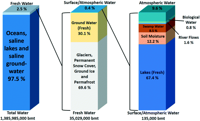 | ||
| Fig. 1 Estimated global water distribution.1 | ||
Water on Earth is subjected to a hydrological cycle in which water continuously changes geographical location by evaporation or sublimation, atmospheric transport, and deposition elsewhere by condensation or freezing. This hydrological cycle interconverts saline and fresh water. The hydrological transportation cycle moves a quantity of 45![[thin space (1/6-em)]](https://www.rsc.org/images/entities/char_2009.gif) 500 billion metric ton (bmt) of water yearly.3 The residence time of water in the stages of this cycle varies from a short average stay of 9 days in the atmosphere to thousands of years in oceans, seas and underground lakes.3,4 The global annual water withdrawal by human activity amounts to ca. 4000 bmt per year, much smaller than the mass of water engaged in the hydrological cycle. Water withdrawn from surface and underground fresh water sources is either consumed or returned to the source short after usage. The consumed part is evaporated or transported to elsewhere in the world in goods and food in which it is contained.2,3 Human interventions for water production accelerate the hydrological cycle as it reduces the water residence time in fresh water states such as ground water. Human water use, even with increasing demand in the future by a growing human population will not disturb the global natural hydrological cycle given its magnitude. Ultimately all water withdrawn by human activity is rendered to the hydrological cycle. The water supply problem arises from the uneven spreading of the hydrological cycle on earth. In many places on a local scale the natural water supply does not match the fresh water demand at all times.2,3,5
500 billion metric ton (bmt) of water yearly.3 The residence time of water in the stages of this cycle varies from a short average stay of 9 days in the atmosphere to thousands of years in oceans, seas and underground lakes.3,4 The global annual water withdrawal by human activity amounts to ca. 4000 bmt per year, much smaller than the mass of water engaged in the hydrological cycle. Water withdrawn from surface and underground fresh water sources is either consumed or returned to the source short after usage. The consumed part is evaporated or transported to elsewhere in the world in goods and food in which it is contained.2,3 Human interventions for water production accelerate the hydrological cycle as it reduces the water residence time in fresh water states such as ground water. Human water use, even with increasing demand in the future by a growing human population will not disturb the global natural hydrological cycle given its magnitude. Ultimately all water withdrawn by human activity is rendered to the hydrological cycle. The water supply problem arises from the uneven spreading of the hydrological cycle on earth. In many places on a local scale the natural water supply does not match the fresh water demand at all times.2,3,5
Surface water accounts for about two third of the fresh water withdrawn by humans, and water from underground reservoirs for the other third.2 The volume of water withdrawal according to different types of human activities in 2014 and a prediction for 2040 are presented in Fig. 2. The agriculture sector currently is by far the main fresh water user, with a volume of ca. 2800 bmt, representing a share of ca. 70%.2,6 The water intensity in this sector is evident considering e.g. the water demand of the production of a kilogram of beef cattle which requires about 15![[thin space (1/6-em)]](https://www.rsc.org/images/entities/char_2009.gif) 000 L water.7,8 In 2014, the water volume for municipal usage, energy generation and industry were about equal (Fig. 2). The energy sector requires water for primary energy production and especially for cooling in thermally driven electricity production. In the chemical industry, water serves as a solvent, and it is a source of H and O atoms for chemicals and materials.2
000 L water.7,8 In 2014, the water volume for municipal usage, energy generation and industry were about equal (Fig. 2). The energy sector requires water for primary energy production and especially for cooling in thermally driven electricity production. In the chemical industry, water serves as a solvent, and it is a source of H and O atoms for chemicals and materials.2
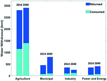 | ||
| Fig. 2 Water withdrawal in different sectors split into a consumed and returned fraction in billion metric ton (bmt) in 2014 and a forecast for 2040. Data extracted from the IEA (2016).2 | ||
The share of withdrawn water returned to the source is dependent on the application (Fig. 2). Irrigation in agriculture is an application where an important share of the water is not returned locally. In the municipal, industrial and power and energy applications, the share of returned water is larger. Nevertheless, overall the consumed amounts are substantial, and this volume is expected to increase by the year 2040 (Fig. 2). An increase by 10% of water withdrawal and a 20% rise in water consumption is expected to occur in the period from 2014 to 2040.2 Municipal water use is primarily dependent on the living standard. Developing countries are facing a strong rise in water needs for the municipal sector.2,6,9
With a growing human population water scarcity is a growing global concern and it is an obstacle for sustainable development. Water scarcity occurs when water resources are below 1000 m3per capita per year.2,5 Currently, water shortage affects about one billion people worldwide and more than three billion people are expected to face this problem by 2025.2 A growing world population, more intensive water usage per capita, desertification and an increasing salt content of fresh water aggravate the water scarcity problem.10,11 The most severe and extreme conditions occur at the local scale, and the ongoing climate change deepens the severity of these local problems.6,12
Water management is complex because all users compete for the same water resources.6 Water is an atypical commodity since scarcity of this good is not always reflected in its price. Artificial low pricing leads to unsustainable and inefficient water usage.2,11 Because of government subsidies water prices are often artificially low, like for energy. Countries with the lowest water and energy prices rank the highest in terms of water consumption and tend to have the least sustainable water production. The strong correlation between water and energy demand complicates the problem even more. The water to be returned to the natural hydrological cycle is in most cases polluted and needs wastewater treatment. Water purification is also energy demanding. Increasing volumes entail enhanced energy consumption and consequently, additional water usage in cooling processes.2 Mastering of this water-energy nexus is essential to achieve sustainable resource management.
There are three ways to resolve local fresh water shortage. First, when the supply from local fresh water sources is insufficient, water transportation over long distances from areas with water abundance is an obvious solution. Second, seawater is an inexhaustible water source (Fig. 1). Desalination of seawater and transportation with pipelines inland is an example of this solution.9,13,14
Finally, an important observation is that atmospheric water is largely sufficient to cover the human fresh water needs (Fig. 1). Liquefaction of water vapour captured locally from atmospheric air is a way to avoid the need of long distance transportation, because it is ubiquitous. Water vapour in the atmosphere is rather clean, and after condensation an attractive source of fresh water, similar to natural precipitation. The atmosphere is an inexhaustible source of water because of the hydrological cycle which replenishes the atmosphere swiftly with water vapour.14 The idea of a decentralised water supply system relying on water extraction from the air has been appealing for decades. Some authors forecasted a bright future for this technology.15–17 The main obstacle for widespread implementation of water-from-air technology is the high energy demand, although at locations with abundant solar energy this is seen as a minor concern.16,18
In this review a thermodynamic analysis of the energy requirement of water production from air is provided. The boundary conditions depending on geographical location can vary substantially and the variability of the water content of atmospheric air and climatological conditions are part of the analysis. Implementing water-from-air technology would have a large impact on the water-energy nexus.
Parameters of water vapour in atmospheric air
Relative humidity (Φ), absolute humidity (ω) and dew-point temperature (Td) are the essential properties of atmospheric air to be used as source of water. Air is a gas mixture, composed of nitrogen, oxygen and argon gas as major components (in this order), and water vapour in variable contents. The relative humidity (Φ) is the ratio of the partial pressure of water vapour (Pw) over the saturation pressure (Ps) (eqn (1)).19,20 | (1) |
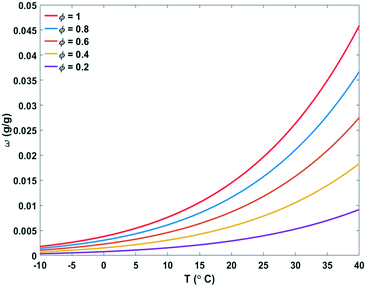 | ||
| Fig. 3 Absolute humidity (ω) and relative humidity (Φ) of air depending on temperature (T). Unsaturated air becomes saturated by lowering the temperature or by increasing the absolute humidity.20 | ||
The mathematical relation between relative humidity (Φ), absolute humidity (ω), total air pressure (P) and temperature (T) is given in eqn (2). The dew-point Td can be obtained from this equation by solving for T and setting Φ = 1 for a given absolute humidity and air pressure.20
 | (2) |
 | (3) |
![[thin space (1/6-em)]](https://www.rsc.org/images/entities/char_2009.gif) 000 Pa, i.e. at 1 bar.
000 Pa, i.e. at 1 bar.| P = Pa + Pw | (4) |
| H = Ha + ωHwv | (5) |
| Ha = Cp,aT | (6) |
| Hwv = Hwv(0 °C) + Cp,wvT | (7) |
Principles of water extraction from air
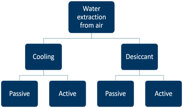
Atmospheric water generators can be divided into categories (Fig. 4). Water vapour can be extracted from the air either by cooling and condensing moisture out of the air, or else, by using a desiccant material. Each category is subdivided into a passive and active way to apply the water extraction method. The term passive indicates water is captured with the help of natural phenomena and without an energy delivery system. In the active case, an external energy vector is implemented to assist the water extraction process. The two most important principles are active cooling and passive water extraction by water vapour ad- or absorption on a desiccant.In the next sections the energy requirements of the different concepts are discussed. A theoretical performance evaluation will be based on the specific water yield SYwater (L kW−1 h−1) which represents the volume of liquid water which can be produced with an energy input of 1 kW h.
Technologies for water extraction from the air
Passive cooling technologies
Dew and fog harvesting are examples of passive cooling. In this section, the advantages and disadvantages of water collection through artificial dew and fog formation and the way to generate the required spontaneous cooling are discussed.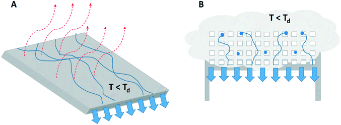 | ||
| Fig. 5 A visual presentation of the process of A) dew harvesting by droplet formation and dripping off a surface cooled below the dew-point by passive radiative cooling (red arrows) and B) fog harvesting where fog droplets (in blue) hit a mesh structure, coalesce and detach from the mesh by gravity.23,24,29 | ||
Any surface outdoor emits energy by radiation of electromagnetic waves in the infrared wavelength region to the sky.25 The available cooling power lies between 25 and 100 W m−2 on cloudless nights. A theoretical maximum water production of 0.8 L m−2 per day under most optimal conditions has been estimated.24,26 Consequently, a large surface area exposed to the sky is needed to collect artificial dew in significant amounts.26
The dew harvesting process faces the problem of inconsistent production caused by the critical condition of sufficient radiative cooling to reach a surface temperature below the dew-point. In addition, wind may interfere with the condensation process. Air flow provides a larger flow of water vapour toward the cold surface, but depending on the temperature of the wind, it also can counteract the radiative cooling. Wind can lift dew drops from the surface and reduce this way the harvesting.26,27 The inconsistency of water production is the main reason why the technique is applied only in specific regions with suitable climate for dew formation.28 The energy efficiency is less relevant for this system since no artificial energy input is needed.
Fog collection is the capturing of the already existing liquid water droplets of air aerosol on a mesh material (Fig. 5B). The droplets grow by coalescence on the mesh and are finally detached from the mesh and collected by gravity.29 The amount of fog that can be harvested depends on relative humidity, absolute humidity, wind velocity and the frequency of fog occurrence.29 Fog harvesting, like dew collection, is a relatively inexpensive, easy and definitely helpful approach in combatting water scarcity, but it is critically depending on climatologic conditions.30 The water collection capacity is depending on external factors rendering the water yield unpredictable.
Special surfaces have been designed for dew harvesting. Thickett et al. illustrated condensation rate improvements during dew harvesting by a micro patterned coating. Water condenses on the hydrophilic coating part and flows consecutively over the hydrophobic area when the droplet detaches from the surface.33 Patterned polymers applied as a condenser coating were shown to promote water vapour condensation rates by 57%.34 The principle is bio-inspired as the same principle is used by the Stenocara beetle in the Namib Desert.33 Beysens et al. reached a 20% increase in dew yield by application of a condenser foil of TiO2 and BaSO4 microspheres in polyethylene.27
Fog serves as a water source for plants and animals such as e.g. in the Atacama Desert in Chile. In these arid areas there is almost no rainfall. On coastal locations at altitudes of 600–1200 m in Chile fog stays in the air for a long time. In those areas, fog extraction can yield water at rates of 1 to 15 L m−2 per day. A maximum of 6.3 L m−2 per day was captured by a polypropylene coated mesh by Cáceres et al.29 An average fog collection of 4.6 L m−2 per day was reported in South Africa.35 Commonly used mesh types are made of nylon or Teflon.36 Park et al. optimised the mesh design to improve fog collection. Based on an extrapolation of reported experimental data at a site in Chile, a production of 12 L m−2 per day is estimated.30
Capturing fog requires less space compared to dew. Fog capture nets can be placed vertically which reduces the overall lateral space requirements.
When fog or dew is common at a specific location it can be a convenient way of providing water to small communities, but for agriculture purposes, the collected quantities are too low.37 Temporal water storage is needed to equilibrate supply and demand when using a dew, fog or even rainwater capturing approach.32
Conductive heat loss to the underground is an alternative way of cooling a condensation surface. In a device operating according to this principle, air is forced to enter an underground metal coil connected to a reservoir for collecting the condensate. The metal coil is in thermal contact to the underground.38,39 The minimum required temperature difference between the underground and atmospheric air derived from the temperature dependence of the relative humidity (Fig. 3) is presented in Table 1.
| Φ amb [%] | T amb [°C] | T amb − Td [°C] |
|---|---|---|
| 80 | 25 | 3.7 |
| 80 | 15 | 3.4 |
| 60 | 25 | 8.3 |
| 60 | 15 | 7.7 |
| 40 | 25 | 14.5 |
| 40 | 15 | 13.5 |
Air at T = 15–25 °C needs to be cooled by ca. 14 °C at Φ = 40%, 8 °C at Φ = 60% and 3.5 °C at Φ = 80% to initiate condensation. This seems to be a small temperature difference, but it is difficult to maintain. Underground heat conduction is slow, and inefficient to dissipate the condensation heat. The temperature of the metal coil will be increased by the water condensation process. The temperature difference between air and underground condensation surface vanishes rapidly.
Consequently, the underground temperature needs to be below that of the condensation coil to keep the condensation coil below the critical temperature needed for water vapour condensation. Literature data on temperature differences between atmospheric air at ground level and underground at 2 m deepness are available for a location in Lecce, Italy.40 Locations with different thermal conductivity of the underground are compared. The temperature difference shows seasonal fluctuations, as expected. The temperature difference between air and underground reaches a maximum of about 8 °C in July. Air at relative humidity below 60% will never reach saturation under these conditions. At 80% relative humidity, temperature differences of 3.5 °C will only be reached in certain months.40 Active cooling of the condensation coils appears to be needed to reach the desired temperature differences.
Active cooling technologies
In this section, active air cooling technologies for water extraction from air are presented. The thermodynamics of these processes and the impact of the climate on the specific water yield and energy efficiency are analysed. Theoretical limitations of the specific water yield depending on ambient temperature and relative and absolute humidity are presented. Energy efficiencies of practical devices based on the reverse Carnot cycle, thermoelectric coolers, self-filling water bottles and membrane assisted water condensation technologies are estimated.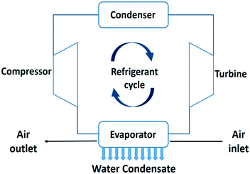 | ||
| Fig. 6 Process flow diagram of an air cooler and water condensation unit using a refrigerant evaporation–condensation cycle.20 | ||
This water extraction concept is based on a reverse Carnot cycle of a coolant. The coefficient of performance of the cooling unit (COPcooling) is defined in eqn (8), with Tc the temperature of the cold reservoir and Th the temperature of the hot reservoir. The hot reservoir is typically at ambient temperature, Tamb.20
 | (8) |
Thermoelectric coolers (TEC) are an alternative to the evaporation–condensation cycle of a coolant. This electricity based technology forces heat transport by application of a voltage difference between a semiconductor pn-junction. The electric current causes cooling on one side of the semiconductor assembly, and heating on the other side.44 TEC based cooling processes are generally less energy efficient, but the absence of a recirculating fluid is a practical advantage.45 In-depth analysis of cooling technologies is beyond the scope of this review.43,46–48
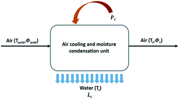
The general process scheme of an active cooling device to condense water vapour out of air is presented in Fig. 7. The theoretical maximum amount of liquid water that can be recovered from air for a given power supply in a 100% efficient process without heat recovery is given by SYwater, a convenient physical quantity to estimate the influence of the climate on the operation of an air cooling system:
 | (9) |
![[L with combining dot above]](https://www.rsc.org/images/entities/i_char_004c_0307.gif) c is the rate of water production (L h−1) and Ṗc, the total power supply (kW).
c is the rate of water production (L h−1) and Ṗc, the total power supply (kW). ![[L with combining dot above]](https://www.rsc.org/images/entities/i_char_004c_0307.gif) c and Ṗc values are obtained from eqn (10) and (11), respectively.
c and Ṗc values are obtained from eqn (10) and (11), respectively.![[L with combining dot above]](https://www.rsc.org/images/entities/i_char_004c_0307.gif) c = ρa c = ρa![[V with combining dot above]](https://www.rsc.org/images/entities/i_char_0056_0307.gif) a(ωamb − ωc) a(ωamb − ωc) | (10) |
![[V with combining dot above]](https://www.rsc.org/images/entities/i_char_0056_0307.gif) a, the volumetric air flow rate (m3 h−1). The power supply Ṗc has two contributions, viz. the energy needed for cooling and water condensation, and the ventilator energy, Ṗv:
a, the volumetric air flow rate (m3 h−1). The power supply Ṗc has two contributions, viz. the energy needed for cooling and water condensation, and the ventilator energy, Ṗv: | (11) |
![[V with combining dot above]](https://www.rsc.org/images/entities/i_char_0056_0307.gif) a the volumetric air flow expressed in (m3 s−1).
a the volumetric air flow expressed in (m3 s−1).Qc = ρa![[V with combining dot above]](https://www.rsc.org/images/entities/i_char_0056_0307.gif) a(Hamb − Hc − (ωamb − ωc)Cp,wTc) a(Hamb − Hc − (ωamb − ωc)Cp,wTc) | (12) |
The condensation temperature Tc has a strong impact on the specific water yield. This is illustrated by comparing two cases in Fig. 8. The first case deals with a humid hot climate characterized by high relative humidity of 80% at a temperature of 25 °C. The second case refers to a desert climate with low relative humidity of 30% at a temperature of 30 °C. Temperatures below 0 °C in the air cooling and moisture condensation unit were not considered because these would involve the complication of ice formation. Practically, it would complicate the water production. Ventilator power values Ṗv and air flow rates ![[V with combining dot above]](https://www.rsc.org/images/entities/i_char_0056_0307.gif) a were taken from axial ventilator specifications.49
a were taken from axial ventilator specifications.49
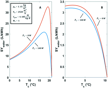 | ||
| Fig. 8 Specific water yield of active cooling technologies against the condensation temperature in A) a humid climate (Φ = 80%, T = 25 °C) and B) a dry climate (Φ = 30%, T = 30 °C). | ||
In the hot humid climate case the dew-point Td is ca. 21 °C (Fig. 8A). The optimal condensation temperature for energy efficient water capturing from air is lower than the dew-point. The specific water yield under these conditions shows a clear maximum at 17 °C (Fig. 8A). In the situation of Fig. 8A the maximum specific water yield (SYmax,water), amounts to 21 L kW−1 h−1. When the ventilator power Ṗv (eqn (11)) is omitted the optimum specific water yield is 32.6 L kW−1 h−1. The situation in a dry climate is different (Fig. 8B). There is a shallow optimum energy efficiency around 3 °C. The yield of liquid water per kW h is small and does not surpass 3.3 L kW−1 h−1 (Fig. 8B). This is mainly a result of the high sensible heat removal requirements.50 The contribution of Ṗv is negligible in this case.
In both climates (Fig. 8), water production ![[L with combining dot above]](https://www.rsc.org/images/entities/i_char_004c_0307.gif) c can be raised by reducing the condensation temperature Tc at the cost of increasing the power supply and operating at lower energy efficiency.
c can be raised by reducing the condensation temperature Tc at the cost of increasing the power supply and operating at lower energy efficiency.
The impact of ambient temperature, absolute humidity and relative humidity on the energy efficiency of water production from air by cooling and condensation was analysed in more detail. The maximum specific water yield for a given climate condition was estimated at the corresponding optimal condensation temperature Tc,opt (eqn (13)).
| SYmax,water = SYwater(Tc,opt) | (13) |
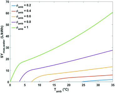 | ||
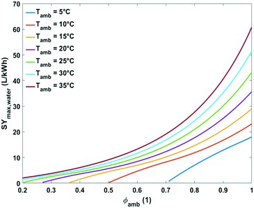
| Fig. 9 Plot of maximum specific water yield as a function of ambient temperature at different relative humidity levels for water extraction from the air by active cooling. | ||
At the lowest possible ambient temperatures for each case the maximum specific water yields are very low. One of the reasons is that the absolute water content of cold air is low. In addition, the most optimal condensation temperature in this instance lies below 0 °C which is impractical. The minimal ambient air temperature necessary for avoiding water freezing in the cooling section of the device at optimal energetic performance was estimated at 3, 7, 13 and 24 °C for relative humidity of 80, 60, 40 and 20%, respectively (Fig. 9).
Above these critical temperatures, the specific water yield increases significantly with increasing ambient temperature. The higher the relative humidity, the more significant the increase (Fig. 9).
Comprehensive plots showing the influence of absolute humidity at different relative humidity values and relative humidity at different ambient temperatures on maximum specific water yield are presented in Fig. 10 and 11, respectively. The specific water yield is little influenced by absolute humidity (Fig. 10). Relative humidity governs the energy intensity to extract water from the air with active cooling technology. The maximum specific water yield increases with relative humidity in an exponential way (Fig. 11).
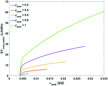 | ||
| Fig. 10 Plot of maximum specific water yield against absolute humidity at different relative humidity levels for water extraction from the air by active cooling. | ||
Some performances of devices are given in Table 2. Provided the relevant data were available, the efficiency (eqn (14)) of reported devices was estimated based on reported specific water yield and an estimated theoretical maximum, defined in eqn (13):
 | (14) |
Portable self-filling water bottles are miniaturised versions of the air cooling and moisture condensation technique. Air driven by a fan is sent inside the bottle where the moisture condenses onto thermoelectric cooling surfaces. The device is powered by a small photovoltaic (PV) panel to minimize size and weight which is essential for a portable bottle.54 A power input of 313 W is required to produce 0.5 L h−1 when only condensation heat needs to be removed and when taking a maximum COPcooling value of 1 for a TEC device.22,45,55 At full irradiation, a PV panel typically delivers 180 W m−2, therefore around 1.7 m2 of solar panel is required to supply enough power.
The specific water yield of TEC based air cooling is estimated to be in the range of 0.14–1.1 L kW−1 h−1.55–58
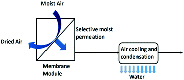 | ||
| Fig. 12 Membrane assisted water condensation setup for water extraction from air.10 | ||
The addition of a membrane module (Fig. 12) has been reported to double the specific water yield. The specific water yield of the modelled membrane dehumidifier setup reached 6.18 L kW−1 h−1 with a 5000 m2 membrane surface area.10 A liquid membrane with hygroscopic salts on a carbon black nanoparticle support has been reported effective in this application.61 Polymer electrolyte membranes are used for electrochemical based air dehumidification, an alternative to the pressure driven membrane dehumidification process. In this process a net water flux over the membrane is created by splitting water electrochemically into oxygen gas and protons at the anode side of the membrane and combining these protons again with the oxygen gas at the cathode side to make water. In addition, water moves through the membrane by the effect of electro-osmosis. Back diffusion lowers the performance of this set-up.62
Hot humid climates like in tropical regions offer the best use cases for this way of producing water. Water scarcity rarely occurs in such climates and the need of water-from-air technology is limited. Close to 100% relative humidity, active cooling may not be needed as dew and fog formation frequently occur under these conditions, and these are easier to collect than water vapour. At the other extreme, in dry climates the dew-point of humid air is below 0 °C which makes the cooling concept impractical because of the need of defrosting the condenser for collecting the harvested water. The condensation temperature could be enhanced above freezing temperature by implementation of a membrane module to increase the relative humidity prior to condensation. The membrane/condenser combination significantly improves the specific water yield. The reduction of energy consumption in the cooling unit can balance the additional investment in a membrane module.
Passive desiccant technologies
Trapping water in solid and liquid desiccants is an alternative to condensation by cooling. Liquid desiccants take up water by absorption. Solid desiccants adsorb water molecules in their porous matrix. Especially in dry and arid regions where the water condensation temperature is too low for practical application, the use of desiccants is an attractive alternative. In this section, the thermodynamics of water-from-air technologies with desiccants are reviewed. The use of the day–night cycle for reversing the water sorption process is discussed.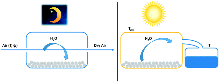 | ||
| Fig. 13 Night and day cycle of passive water extraction from air with a desiccant (grey spheres). Water adsorbs at night from cold air on desiccant material and desorbs by solar heating during the day. Water vapour desorbing from the adsorbent is condensed in a separate container.63 | ||
The determination of the water extraction capacity from adsorption and desorption branches of the adsorption isotherm are explained in Fig. 14. During the night the desiccant is saturated with water vapour according to the isotherm pertaining to the cold temperature, Tads. During the day, the volume holding the saturated desiccant is heated by sunlight to Tdes, which also lowers the relative humidity. This causes desorption according to the adsorption isotherm at the desorption temperature. The difference between both states (qads at Tads) and (qdes at Tdes) defines the extractable amount of water in a night and day cycle.66 The adsorption isotherm of a desiccant at Tads and Tdes defines the suitability of an adsorbent to serve atmospheric water harvesting.
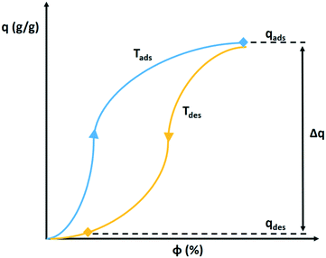 | ||
| Fig. 14 Hypothetical adsorption and desorption isotherm of water vapour on a solid desiccant. The extractable amount of water Δq corresponds to the difference in adsorbed amount at the relative humidity during night at cold temperature Tads and during the day at high temperature Tdes.66 | ||
The shifting of the adsorption isotherm on the relative humidity axis with temperature is dependent on the isosteric heat of adsorption.67 A large isosteric heat of adsorption results in a large shift and a large amount of water that can be produced in the cycle.
The theoretical maximum specific water yield of passive desiccant based systems was estimated for the process and its parameters depicted in Fig. 13. If included, a ventilator with the same specifications as for the previously discussed active air cooling systems was considered (see legend of Fig. 8). The fan delivers air to the desiccant during the night and transports the hot humid air to the condenser during the day. All water of the inlet air is considered to be adsorbed. The adsorption heat is assumed to be dissipated and no energy input is considered to be needed for this step. During the day, the temperature is raised by solar heating. The condenser at the end of the process (Fig. 13) is operated at constant ambient temperature and its energy need is neglected in the thermodynamic analysis.
The heat of desorption is dependent on the desiccant material, temperature and uptake at which the process is operated, reflected in the adsorption isotherm. A water desorption enthalpy of 3.3 kJ g−1 is assumed here, which corresponds to an average value for zeolites and MOF materials at high relative humidity. The desorption heat can be significantly higher at extremely low relative humidities.68,69 The day and night temperatures are considered to be constant for simplicity. The desorption temperature is selected in the range of 40–80 °C.70–72
The specific water yield of a desiccant based process (eqn (15)) is defined as
 | (15) |
![[L with combining dot above]](https://www.rsc.org/images/entities/i_char_004c_0307.gif) d (L h−1), equals the water volume captured during the night.
d (L h−1), equals the water volume captured during the night.![[L with combining dot above]](https://www.rsc.org/images/entities/i_char_004c_0307.gif) d = ρa d = ρa![[V with combining dot above]](https://www.rsc.org/images/entities/i_char_0056_0307.gif) aωamb aωamb | (16) |
Ṗd = (ΔHdes + Cp,w(Tdes − Tatm))![[L with combining dot above]](https://www.rsc.org/images/entities/i_char_004c_0307.gif) d + Ṗv d + Ṗv | (17) |
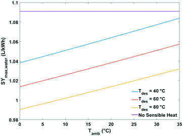 | ||
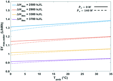
| Fig. 15 Maximum specific water yield of a passive solid desiccant based water-from-air extraction device against ambient temperature. The curves pertain to different desorption temperatures. | ||
The heat of water desorption from the adsorbent has the strongest impact on the specific water yield (Fig. 16). Using adsorbents with a lower heat of desorption enhances the specific water yield. Ventilator power requirements are negligible relative to the heat of desorption.
 | (18) |
| Ref. | Geographic location | Desiccant material | Water harvested per cycle (L kg−1) and (L m−2) | SYwater (L kW−1 h−1) | η d (%) | |
|---|---|---|---|---|---|---|
| a SYmax,water = 1.09 L kW−1 h−1 (ΔHdes = 3300 kJ L−1, Ṗv = 0 W, no sensible heat). b Φ amb = 36–54%, Tamb = 25–35 °C, solar flux: 0.2–0.8 kW m−2. c Daily total radiation: 17.8 MJ m−2. d Φ amb = 40–80%, Tamb = 25–30 °C, solar flux: 0.3–0.88 kW m−2. e T amb = 20–33 °C. f Φ amb = 26–34%, Tamb = 20–32 °C, solar flux: 1.1 kW m−2. g Φ amb = 30%, Tamb = 30 °C, solar flux: 0.6–0.8 kW m−2. h Data of first cycle batch-process, solar flux: 0.525 kW m−2. i Φ amb = 60–70%, Tamb = 26 °C, average solar flux: 1.06 kW m−2. j Φ amb = 25–35%, Tamb = 30 °C, average solar flux: 0.603 kW m−2. | ||||||
| 14 | Egypt | CaCl2 (liquid) | 0.52 | 1.12 | 0.24b | 22 |
| 73 | Shanghai | CaCl2 in MCM-41 matrix (solid) | 0.54 | 1.34 | 0.27c | 25 |
| 74 | India | CaCl2 in sawdust (solid) | 0.18 | 0.5 | 0.16d | 15 |
| 25 | Egypt | CaCl2 (liquid) | — | 0.63 | 0.19e | 17 |
| 64 | Tempe, Arizona | MOF-801 (solid) | 0.28 | 0.34 | 0.15f | 14 |
| 76 | Shanghai | LiCl in MIL-101(Cr) (solid) | 0.45 | 0.4 | 0.37g | 34 |
| 77 | Thuwal | LiCl in hollow carbon spheres (solid) | 0.61 | 0.50 | 0.71h | 65 |
| 78 | Thuwal | PAM-CNT-CaCl2 hydrogel | 0.57 | 2 | 0.75i | 69 |
| 75 | Hail City | CaCl2 (anhydrous) | 0.13 | 0.47 | 0.12j | 11 |
Calcium chloride solutions either unsupported or supported on solids like the ordered mesoporous silica material MCM-41 and sawdust have been investigated.14,25,73,74 MOF-801 is a porous crystalline metal organic framework consisting of zirconium fumarate.64 A tubular solar still filled with CaCl2 was reported to produce water at a yield of 0.47 L m−2 in extreme climate conditions at 25–35% relative humidity.75 Metal–organic framework MIL-101(Cr) encapsulating LiCl has been successfully demonstrated in a water harvesting device.76 A large specific water yield was reached with LiCl encapsulated in hollow carbon spheres. The carbon collects solar heat efficiently and conducts it directly to the desiccant.77 Carbon nanotubes (CNT) behaved similarly in polyacrylamide-CNT-CaCl2 composite material.78 The addition of gravel to a desiccant material to help store thermal energy has also shown to improve the specific water yield.79
The water harvesting with these systems is in the range of 0.1–0.6 L kg−1, and 0.3–2 L m−2 (Table 3). The thermodynamic efficiencies of these passive solar heating devices are in the range of 10–70%. Direct comparison of the performances of the different desicants is not possible since the experimental conditions were different.14,25,64,73,74 Heating of the condenser surface by sunlight, heat losses to the surroundings and an excess of available solar energy relative to adsorbed water quantity can lead to drops in energy efficiency.75,77,80
Strong synergy between poly-NIPAM thermo-responsive polymer and chloride-doped polypyrrole (PPy-Cl) was recently achieved in a super moisture-absorbent gel (SMAG).82
Water vapour is adsorbed on the hygroscopic PPy-Cl phase and transferred to the super-hydrophilic poly-NIPAM, which can store large amounts of liquid water. The water capacity amounts to 6.7, 3.4, and 0.7 g g−1 at a relative humidity of 90, 60, and 30%, respectively. A temperature rise above hydrophilic/hydrophobic switching temperature of the SMAG (40 °C) leads to shrinkage and expulsion of liquid water. In cyclic operation of SMAG up to 50% of the water content of the saturated SMAG can be collected. Specific water yields of 0.21, 3.71 and 9.28 L kW−1 h−1 were achieved at relative humidities of 30, 60 and 90%, respectively. At low relative humidity, the specific water yield of SMAG (0.21 L kW−1 h−1) is in the range of CaCl2 systems and MOFs (Table 3). The performance of SMAG in passive conditions at high relative humidity is spectacular and potentially surpasses the performance of active cooling (discussed higher), but these excellent SMAG performances in real conditions outdoor still needs further investigation.82
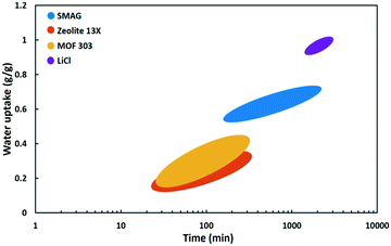 | ||
| Fig. 17 Water uptake as a function of time at Φ = 30% of SMAG (polymer),82 zeolite 13X,87 MOF-303 (ref. 71) and LiCl (salt). | ||
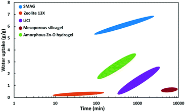 | ||
| Fig. 18 Wate uptake as a function of time at Φ = 90% of SMAG (polymer),82 zeolite 13X,87 hydrogel,85 mesoporous silica gel86 and LiCl (salt). | ||
At 90% relative humidity (Fig. 18) the SMAG has by far the highest capacity (6.7 g g−1), reached in about 2000 minutes. After 100 minutes the water uptake reaches already 5.4 g g−1.82 LiCl salt keeps on absorbing water vapour and reaches a water content of ca. 2.5 g g−1 after 3000 minutes. A nanoporous super hygroscopic hydrogel based on an amorphous oxygen and zinc matrix is able to absorb 3.6 g g−1 after 720 min.85 The water adsorption capacity of zeolite 13X is limited. Zeolites are known for their high affinity for water, but the capacity is limited to the pore volume, which for zeolites does not exceed 0.4 mL g−1.87 Silica gel is a well-known desiccant. It has high capacity, but the adsorption kinetics are extremely slow. In the example of a mesoporous silica gel in Fig. 18, after 10![[thin space (1/6-em)]](https://www.rsc.org/images/entities/char_2009.gif) 000 minutes there is hardly 0.7 g g−1 adsorbed.86
000 minutes there is hardly 0.7 g g−1 adsorbed.86
| Ref. | Desiccant material | Regeneration temperature (°C) | Fraction desorbed (%) |
|---|---|---|---|
| 72 | Silica type 3A | 90 | 95 |
| 71, 88 | Zeolite 13X | 120; 600 | 83; 100 |
| 71 | MOF-303 | 85 | 100 |
| 65, 89 | MOF-801 | 85 | 100 |
| 82 | SMAG | 40; 160 | 40; 100 |
| 68 | MgSO4 | 80 | 31 |
| 73 | CaCl2 in MCM-41 matrix | 80 | 90 |
| 92 | CaCl2 in alginate matrix | 100; 150 | 90; 100 |
| 68 | CaCl2 | 80 | 31 |
| 68 | FeCl3 | 80 | 57 |
| 93 | LiCl impregnated in cloth | 85 | 100 |
| 85 | Amorphous Zn–O hydrogel | 55 | 99 |
Estimation of the maximum specific water yield when using liquid desiccants is more complicated than for a solid adsorbent. Concentrated solutions of inorganic salt are typical examples of liquid absorbents.90 Such solutions keep on absorbing water such that in a practical timeframe of a night and day cycle thermodynamic absorption equilibrium is never reached. It may explain some contradicting statements in literature. Some authors state that liquid desiccants are able to capture more water on weight basis than solid adsorbents and are more productive.70 Aqueous desiccants would have advantages over solid desiccants when solar heating is used for regeneration because the regeneration temperature of liquid desiccants is generally lower than for solid adsorbents.61,70,91 Other authors claim solid adsorbents to be the best choice.64,73 The regeneration requirements of liquid and solid desiccants are relatively similar.
Active desiccant technologies
Passive desiccant systems rely on the day-night cycle and produce water discontinuously.71 Continuous water production is made possible by implementing an artificial energy supply. This section provides a description of such active water capturing devices with desiccants. The principles of the use of desiccants are similar to the passive systems. The difference resides in the regeneration which is activated by an auxiliary energy source. The maximum specific water yield of the active desiccant technology will therefore be comparable with the energy requirements of the passive desiccant case. | ||
| Fig. 19 Process flow diagram of the active desiccant technology based on the desiccant wheel design.94 | ||
Some modifications of this principle have been proposed. Instead of a wheel a two-bed system can be used with the beds alternating between adsorption and regeneration mode.90 A discontinuous process is another alternative.95 The desiccant wheel is not suited for handling liquid desiccants. In that case pumping equipment is installed to transport the desiccant material from absorption to regeneration section of the unit.94 Complex systems with a liquid desiccant have been analysed with mathematical models.96,97
Moving from a passive to an active desiccant based system has its trade-offs. The desiccant is used more efficiently in the active system, which reduces the desiccant material costs for a given water production rate. Active systems are technically more complicated, and require an external energy supply. The footprint of active desiccant based systems is smaller than for passive systems, but for providing the auxiliary energy, solar panels and solar collectors occupy additional space. The principles of active water extraction using a desiccant have already been put to practice long time ago in the field of air conditioning. A review of the early days of desiccant dehumidification technology is provided in a review of desiccant dehumidification technology by A. Pesaran.94
The technology is based on an adsorption/desorption cycle by using a desiccant wheel.99 The middle section produces electricity by photovoltaic panels. The regeneration heat is produced in the heat absorbing panels positioned left and right of it. The panel produces water only during daytime.100 The major advantage of this standalone device is its applicability in isolated and remote areas where grid power is unavailable.
From the data provided in different environmental conditions, the specific water yield is estimated at 0.14–0.32 L kW−1 h−1.100 These values are in the range of passive desiccant based devices with classic adsorbents (Table 3).
Similar specific water yields of 0.3–1 L kW−1 h−1 depending on environmental parameters have been reported for related devices. Internal heat recovery increases the dehumidifier performance.101,102 Wang et al. reached an SYwater of 0.84 L kW−1 h−1 by using LiCl enclosed in an active carbon felt matrix as adsorbent and an electric heater for the discontinuous desorption stage.95 The high efficiency can be explained by the humid conditions under which this excellent performance was achieved in combination with an efficient heater. An active desiccant based device reported by Hanikel et al. with MOF-303 adsorbent has been demonstrated in the Mojave Desert. Even under those challenging climate conditions a specific water yield of 0.19 L kW−1 h−1 could be reached.71
Water from air and the water-energy nexus
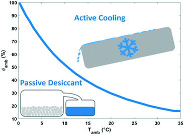
The energy demand of water-from-air technologies is significant, and the potential of water harvesting form the atmosphere is part of the water-energy nexus. The climate dictates the technology to be advised. Dew and fog harvesting show potential in areas with periods with 100% relative humidity. When this condition is not met, other water-from-air technologies have to be considered. From the analysis of the different concepts in this review, passive desiccant technologies and active cooling emerged as most promising technologies. The climatological conditions favouring active cooling versus passive desiccant technology depending on relative humidity and ambient temperature are indicated in Fig. 20. Passive desiccant based systems with desorption temperature of 80 °C (Fig. 15) are considered; and active cooling according to the description in Fig. 9. Active cooling is the preferred choice in hot and wet climates, a generally recommended guideline in dehumidification technology.103 This conclusion was also reached previously by Gido et al.37 In dry and hot regions especially vulnerable to water scarcity, desiccant technologies are the best and only choice when considering the atmosphere as a water source.Fig. 21 summarises the specific water yield reached for different types of water-from-air technologies relative to the maximum specific water yield. Relatively high specific water yields can only be reached with active cooling. Opting for desiccant technology in arid regions will lead to low specific water yields. A specific water yield of 0.1–4 L kW−1 h−1 is characteristic for water-from-air technology. This is very low compared to conventional water production techniques like reverse osmosis desalination, which reaches specific water yields of 250 L kW−1 h−1.104
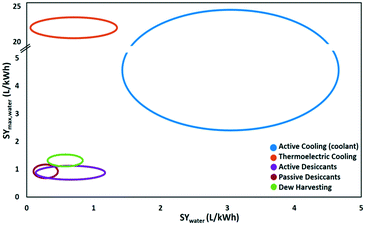 | ||
| Fig. 21 The maximum specific water yield and the achieved specific water yield of five different water-from-air technologies. | ||
The limited productivity according to the state-of-the-art (∼1 L m−2, Table 3), limits the application potential of passive desiccant water extraction to small communities.70 Applications with high water demand like agriculture are problematic.
The active desiccant case could overcome the scaling problem for water production when use is made of grid electricity. In that case electricity generation should not involve water consumption. Thermoelectric power plants consume on average 1.25 L kW−1 h−1 (ref. 105) which exceeds even the specific water yield to be expected (Table 3). Innovation in adsorbent materials and concepts for water-from-air technologies is needed. The advent of thermo-responsive polymers and their enhanced specific water yields reached at laboratory scale is promising.
Conclusion
The maximum specific water yield (L kW−1 h−1) is a consistent parameter to evaluate water-from-air technologies and indicate the preferred climate conditions for their operation.The use of dew and fog harvesting is advantageous when the air carries airborne liquid water droplets. But in humid climate with frequent dew and fog, water scarcity is seldom a problem. Unpredictable and low water output per surface area are major drawbacks of this inexpensive technology. A continuous water output is achieved with the active cooling approach by using forced air convection over a condenser. Active cooling is the most energy efficient way to extract water from the air in mid to high relative humidity regions and warm climates. In this approach the maximum specific water yield decreases exponentially with decreasing relative humidity. The cooling principle cannot be applied in low relative humidity climates because of dew-points below 0 °C causing freezing of the collected water. An active cooling system can be favourably assisted by a membrane module to enhance the relative humidity artificially. A more common approach in dry climates is the application of desiccant materials. Research in this area has mostly been concentrated on new material development. This led to the introduction of several new desiccant materials like MOFs which show lower desorption temperatures, improved adsorption kinetics and better applicability in extremely arid regions with a relative humidity around 30%. Salts like CaCl2 and LiCl have been shown to be efficient in these harsh conditions as well. The specific water yields achieved with desiccants is relatively low and the theoretical limits are within reach. Despite the recent advances in desiccant materials and process engineering the intrinsic energy intensity remains a major obstacle. The introduction of fundamentally new concepts is needed to cause a step change in energy performance. Some thermo-responsive polymers display hydrophilic to hydrophobic phase transitions at temperatures when water is still liquid. A promising specific water yield of ca. 9 L kW−1 h−1 at 90% relative humidity has been reported, surpassing current cooling and desiccant based technologies. The performance under more challenging conditions of low relative humidity remains to be demonstrated. There is plenty of water in the atmosphere, but harvesting it in an energy efficient way remains one of the grand scientific challenges. Introducing fundamentally new concepts may be key in making this technology a viable solution to combat water scarcity.
Conflicts of interest
There are no conflicts to declare.Acknowledgements
This publication has received funding from the European Research Council (ERC) under the European Union's Horizon 2020 research and innovation programme (grant agreement No. [834134]), and long-term structural funding from the Flemish Government (Methusalem funding).Notes and references
- I. A. Shiklomanov, in Water in Crisis A Guide to the World's Fresh Water Resources, ed. P. H. Gleick, Oxford University Press, 1993, pp. 13–24 Search PubMed.
- IEA, Water- Energy Nexus, 2016 Search PubMed.
- T. Oki and S. Kanae, Global Hydrological Cycles and World Water Resources, Science, 2006, 313, 1068–1072 CrossRef CAS PubMed.
- R. J. Van Der Ent and O. A. Tuinenburg, The residence time of water in the atmosphere revisited, Hydrol. Earth Syst. Sci., 2017, 21, 779–790 CrossRef.
- A. Brown and M. D. Matlock, A Review of Water Scarcity Indices and Methodologies, Sustain. Consort., 2011, p. 19 Search PubMed.
- W. A. Jury and H. Vaux, The role of science in solving the world's emerging water problems, Proc. Natl. Acad. Sci. U. S. A., 2005, 102, 15715–15720 CrossRef CAS PubMed.
- M. M. Mekonnen and A. Y. Hoekstra, The green, blue and grey water footprint of crops and derived crop products, 2010, vol. 1 Search PubMed.
- F. R. Rijsberman, Water scarcity: Fact or fiction?, Agric. Water Manag., 2006, 80, 5–22 CrossRef.
- A. Y. Hoekstra, A. K. Chapagain, M. M. Aldaya and M. M. Mekonnen, The water footprint assessment manual: setting the global standard, 2011 Search PubMed.
- D. Bergmair, S. J. Metz, H. C. de Lange and A. A. van Steenhoven, System analysis of membrane facilitated water generation from air humidity, Desalination, 2014, 339, 26–33 CrossRef CAS.
- L. Guppy and K. Anderson, Water Crisis Report, 2017 Search PubMed.
- A. A. Harpold and P. D. Brooks, Humidity determines snowpack ablation under a warming climate, Proc. Natl. Acad. Sci. U. S. A., 2018, 115, 1215–1220 CrossRef CAS PubMed.
- Bureau of International Information Program, Global Water Issues, 2011 Search PubMed.
- H. E. Gad, A. M. Hamed and I. I. El-Sharkawy, Application of a solar desiccant/collector system for water recovery from atmospheric air, Renewable Energy, 2001, 22, 541–556 CrossRef CAS.
- Y. Tu, R. Wang, Y. Zhang and J. Wang, Progress and Expectation of Atmospheric Water Harvesting, Joule, 2018, 1–24 Search PubMed.
- A. A. Salehi, M. Ghannadi-Maragheh, M. Torab-Mostaedi, R. Torkaman and M. Asadollahzadeh, A review on the water-energy nexus for drinking water production from humid air, Renewable Sustainable Energy Rev., 2020, 120, 109627 CrossRef.
- H. Jarimi, R. Powell and S. Riffat, Review of sustainable methods for atmospheric water harvesting, Int. J. Low-Carbon Technol., 2020, 1–24 Search PubMed.
- A. LaPotin, H. Kim, S. R. Rao and E. N. Wang, Adsorption-Based Atmospheric Water Harvesting: Impact of Material and Component Properties on System-Level Performance, Acc. Chem. Res., 2019, 52, 1588–1597 CrossRef CAS PubMed.
- R. E. Gabler, J. F. Petersen, L. M. Trapasso and D. Sack, in Physical Geography, 9th edn, 2008, pp. 144–148 Search PubMed.
- Y. A. Cengel and M. A. Boles, Thermodynamics an engineering approach, McGraw-Hill, 5th edn, 2006 Search PubMed.
- O. A. Alduchov and R. E. Eskridge, Improved Magnus Form Approximation of Saturation Vapor Pressure, J. Appl. Meteorol., 1996, 35, 601–609 CrossRef.
- F. P. Incropera, D. P. Dewitt, T. L. Bergman and A. S. Lavine, Principles of Heat and Mass Transfer, 7th edn, 2013 Search PubMed.
- S. H. Jeon, K. H. Hwang, H. J. Seo, J. S. Lee, J. H. Yu, W. S. Jung, J. H. Boo and S. H. Yun, Selective control of wetting on various substrates, Mater. Res. Bull., 2014, 58, 32–34 CrossRef CAS.
- M. Muselli, D. Beysens, M. Mileta and I. Milimouk, Dew and rain water collection in the Dalmatian Coast, Croatia, Atmos. Res., 2009, 92, 455–463 CrossRef.
- M. A. Talaat, M. M. Awad, E. B. Zeidan and A. M. Hamed, Solar-powered portable apparatus for extracting water from air using desiccant solution, Renewable Energy, 2018, 119, 662–674 CrossRef CAS.
- O. Clus, P. Ortega, M. Muselli, I. Milimouk and D. Beysens, Study of dew water collection in humid tropical islands, J. Hydrol., 2008, 361, 159–171 CrossRef.
- D. Beysens, I. Milimouk, V. Nikolayev, M. Muselli and J. Marcillat, Using radiative cooling to condense atmospheric vapor: A study to improve water yield, J. Hydrol., 2003, 276, 1–11 CrossRef CAS.
- S. M. Berkowicz, D. Beysens, I. Milimouk, B. G. Heusinkveld, M. Muselli, E. Wakshal and A. F. G. Jacobs, in The Third International Conferene on Fog, Fog Collection and Dew, Pretoria, 2004 Search PubMed.
- L. Cáceres, B. Gómez-Silva, X. Garró, V. Rodríguez, V. Monardes and C. P. McKay, Relative humidity patterns and fog water precipitation in the Atacama Desert and biological implications, J. Geophys. Res.: Biogeosci., 2007, 112, 1–11 Search PubMed.
- K. C. Park, S. S. Chhatre, S. Srinivasan, R. E. Cohen and G. H. McKinley, Optimal design of permeable fiber network structures for fog harvesting, Langmuir, 2013, 29, 13269–13277 CrossRef CAS PubMed.
- B. Khalil, J. Adamowski, A. Shabbir, C. Jang, M. Rojas, K. Reilly and B. Ozga-Zielinski, A review: dew water collection from radiative passive collectors to recent developments of active collectors, Sustain. Water Resour. Manag., 2016, 2, 71–86 CrossRef.
- G. Sharan, A. K. Roy, L. Royon, A. Mongruel and D. Beysens, Dew plant for bottling water, J. Cleaner Prod., 2017, 155, 83–92 CrossRef.
- S. C. Thickett, C. Neto and A. T. Harris, Biomimetic surface coatings for atmospheric water capture prepared by dewetting of polymer films, Adv. Mater., 2011, 23, 3718–3722 CrossRef CAS PubMed.
- O. Al-Khayat, J. K. Hong, D. M. Beck, A. I. Minett and C. Neto, Patterned Polymer Coatings Increase the Efficiency of Dew Harvesting, ACS Appl. Mater. Interfaces, 2017, 9, 13676–13684 CrossRef CAS PubMed.
- J. Olivier, Fog harvesting: An alternative source of water supply on the West Coast of South Africa, GeoJournal, 2004, 61, 203–214 CrossRef.
- H. G. Andrews, E. A. Eccles, W. C. E. Schofield and J. P. S. Badyal, Three-dimensional hierarchical structures for fog harvesting, Langmuir, 2011, 27, 3798–3802 CrossRef CAS PubMed.
- B. Gido, E. Friedler and D. M. Broday, Assessment of atmospheric moisture harvesting by direct cooling, Atmos. Res., 2016, 182, 156–162 CrossRef.
- Indiegogo, WaterSeer, (accessed 12 November 2019), https://www.indiegogo.com/projects/waterseer#/.
- TreeHugger, Wind-powered device can produce 11 gallons per day of clean drinking water from the air, (accessed 10 December 2019), https://www.treehugger.com/clean-technology/waterseer-can-produce-11-gallons-day-clean-drinking-water-air.html Search PubMed.
- P. M. Congedo, C. Lorusso, M. G. de Giorgi and D. Laforgia, Computational fluid dynamic modeling of horizontal air-ground heat exchangers (HAGHE) for HVAC systems, Energies, 2014, 7, 8465–8482 CrossRef.
- E. Granryd, Hydrocarbons as refrigerants - an overview, Int. J. Refrig., 2001, 24, 15–24 CrossRef CAS.
- J. M. Calm, The next generation of refrigerants - Historical review, considerations, and outlook, Int. J. Refrig., 2008, 31, 1123–1133 CrossRef CAS.
- R. J. Dossat, Principles Of Refrigeration, John Wiley & Sons Inc., New York and London, 1961 Search PubMed.
- R. M. Atta, Solar Water Condensation Using Thermoelectric Coolers, Int. J. Water Resour. Arid Environ., 2011, 1, 142–145 Search PubMed.
- S. B. Riffat and X. Ma, Improving the coefficient of performance of thermoelectric cooling systems: A review, Int. J. Energy Res., 2004, 28, 753–768 CrossRef.
- J. Steven Brown and P. A. Domanski, Review of alternative cooling technologies, Appl. Therm. Eng., 2014, 64, 252–262 CrossRef CAS.
- B. R. Hughes, H. N. Chaudhry and S. A. Ghani, A review of sustainable cooling technologies in buildings, Renewable Sustainable Energy Rev., 2011, 15, 3112–3120 CrossRef.
- A. A. Iqbal and A. Al-Alili, Review of Solar Cooling Technologies in the MENA Region, J. Sol. Energy Eng., 2019, 141, 010801 CrossRef.
- Blaub. Vent., Industrial Ventilation, (accessed 12 November 2019), https://blaubergventilatoren.de/uploads/download/blcatalogueind201701en.pdf.
- B. Gido, E. Friedler and D. M. Broday, Liquid-Desiccant Vapor Separation Reduces the Energy Requirements of Atmospheric Moisture Harvesting, Environ. Sci. Technol., 2016, 50, 8362–8367 CrossRef CAS PubMed.
- Green Energy Efficient Homes, Energy efficient dehumidifiers, (accessed 12 November 2019), http://www.green-energy-efficient-homes.com/energy-efficient-dehumidifiers.html.
- EPA Energy Star, ENERGY STAR Certified Dehumidifiers (accessed 24 April 2018), https://www.energystar.gov/productfinder/product/certified-dehumidifiers/results.
- Quest 105, 155, 205 Dual, (accessed 12 November 2019), https://www.questclimate.com/pdf/Quest-105-155-205-Dual-Spec-Sheet.pdf.
- Indiegogo, Fontus - The Self Filling Water Bottles, (accessed 12 November 2019), https://www.indiegogo.com/projects/fontus-the-self-filling-water-bottles-sport-camping#/.
- A. H. Shourideh, W. Bou Ajram, J. Al Lami, S. Haggag and A. Mansouri, A comprehensive study of an atmospheric water generator using Peltier effect, Therm. Sci. Eng. Prog., 2018, 6, 14–26 CrossRef.
- F. Tan and S. Fok, Experimental Testing and Evaluation of Parameters on the Extraction of Water from Air Using Thermoelectric Coolers, J. Test. Eval., 2013, 41, 96–103 Search PubMed.
- C. Udomsakdigool, J. Hirunlabh, J. Khedari and B. Zeghmati, Design optimization of a new hot heat sink with a rectangular fin array for thermoelectric dehumidifiers, Heat Transfer Eng., 2007, 28, 645–655 CrossRef CAS.
- J. G. Vián, D. Astrain and M. Domínguez, Numerical modelling and a design of a thermoelectric dehumidifier, Appl. Therm. Eng., 2002, 22, 407–422 CrossRef.
- Water from Air- Make Water straight from the Air - Pure drinking water, (accessed 12 November 2019), https://www.waterfromair.co.za/.
- Watergen, GEN–M: Medium Scale, (accessed 12 November 2019), https://us.watergen.com/wp-content/uploads/2019/11/GEN-M.pdf.
- A. Kudasheva, Y. J. Liu and A. Ito, Aqueous salt solution liquid membranes, supported by nanoparticles, for water extraction from the atmosphere via air dehumidification, J. Chem. Technol. Biotechnol., 2018, 93, 2851–2859 CrossRef CAS.
- R. Qi, D. Li and L. Z. Zhang, Performance investigation on polymeric electrolyte membrane-based electrochemical air dehumidification system, Appl. Energy, 2017, 208, 1174–1183 CrossRef CAS.
- Y. Alayli, N. E. Hadji and J. Lebond, A New Process for the extraction of water from air, Desalination, 1987, 67, 227–229 CrossRef CAS.
- H. Kim, S. R. Rao, E. A. Kapustin, L. Zhao, S. Yang, O. M. Yaghi and E. N. Wang, Adsorption-based atmospheric water harvesting device for arid climates, Nat. Commun., 2018, 9, 1191 CrossRef PubMed.
- H. Kim, S. Yang, S. R. Rao, S. Narayanan, E. A. Kapustin, H. Furukawa, A. S. Umans, O. M. Yaghi and E. N. Wang, Water harvesting from air with metal-organic frameworks powered by natural sunlight, Science, 2017, 356, 430–434 CrossRef CAS PubMed.
- F. Fathieh, M. J. Kalmutzki, E. A. Kapustin, P. J. Waller, J. Yang and O. M. Yaghi, Practical water production from desert air, Sci. Adv., 2018, 4, eaat3198 CrossRef PubMed.
- S. Poyet and S. Charles, Temperature dependence of the sorption isotherms of cement-based materials: Heat of sorption and Clausius-Clapeyron formula, Cem. Concr. Res., 2009, 39, 1060–1067 CrossRef CAS.
- R. Li, Y. Shi, L. Shi, M. Alsaedi and P. Wang, Harvesting Water from Air : Using Anhydrous Salt with Sunlight, Environ. Sci. Technol., 2018, 52, 5398–5406 CrossRef CAS PubMed.
- H. Kim, H. J. Cho, S. Narayanan, S. Yang, H. Furukawa, S. Schiffres, X. Li, Y. B. Zhang, J. Jiang, O. M. Yaghi and E. N. Wang, Characterization of Adsorption Enthalpy of Novel Water-Stable Zeolites and Metal-Organic Frameworks, Sci. Rep., 2016, 6, 1–8 CrossRef PubMed.
- M. H. Mohamed, G. E. William and M. Fatouh, Solar energy utilization in water production from humid air, Sol. Energy, 2017, 148, 98–109 CrossRef CAS.
- N. Hanikel, M. S. Prévot, F. Fathieh, E. A. Kapustin, H. Lyu, H. Wang, N. J. Diercks, T. G. Glover and O. M. Yaghi, Rapid Cycling and Exceptional Yield in a Metal-Organic Framework Water Harvester, ACS Cent. Sci., 2019, 5, 1699–1706 CrossRef CAS PubMed.
- K. C. Ng, H. T. Chua, C. Y. Chung, C. H. Loke, T. Kashiwagi, A. Akisawa and B. B. Saha, Experimental investigation of the silica gel-water adsorption isotherm characteristics, Appl. Therm. Eng., 2001, 21, 1631–1642 CrossRef CAS.
- J. G. Ji, R. Z. Wang and L. X. Li, New composite adsorbent for solar-driven fresh water production from the atmosphere, Desalination, 2007, 212, 176–182 CrossRef CAS.
- M. Kumar and A. Yadav, Experimental investigation of solar powered water production from atmospheric air by using composite desiccant material ‘CaCl2/saw wood’, Desalination, 2015, 367, 216–222 CrossRef CAS.
- M. Elashmawy, Experimental study on water extraction from atmospheric air using tubular solar still, J. Cleaner Prod., 2020, 249, 119322 CrossRef.
- J. Xu, T. Li, J. Chao, S. Wu, T. Yan, W. Li, B. Cao and R. Wang, Efficient Solar-Driven Water Harvesting from Arid Air with Metal–Organic Frameworks Modified by Hygroscopic Salt, Angew. Chem., Int. Ed., 2020, 59, 2–11 CrossRef.
- R. Li, Y. Shi, M. Wu, S. Hong and P. Wang, Improving atmospheric water production yield: Enabling multiple water harvesting cycles with nano sorbent, Nano Energy, 2020, 67, 104255 CrossRef CAS.
- R. Li, Y. Shi, M. Alsaedi, M. Wu, L. Shi and P. Wang, Hybrid Hydrogel with High Water Vapor Harvesting Capacity for Deployable Solar-Driven Atmospheric Water Generator, Environ. Sci. Technol., 2018, 52, 11367–11377 CrossRef CAS PubMed.
- M. Elashmawy, Improving the performance of a parabolic concentrator solar tracking-tubular solar still (PCST-TSS) using gravel as a sensible heat storage material, Desalination, 2020, 473, 114182 CrossRef.
- A. E. Kabeel, S. W. Sharshir, G. B. Abdelaziz, M. A. Halim and A. Swidan, Improving performance of tubular solar still by controlling the water depth and cover cooling, J. Cleaner Prod., 2019, 233, 848–856 CrossRef.
- K. Matsumoto, N. Sakikawa and T. Miyata, Thermo-responsive gels that absorb moisture and ooze water, Nat. Commun., 2018, 9, 2315 CrossRef PubMed.
- F. Zhao, X. Zhou, Y. Liu, Y. Shi, Y. Dai and G. Yu, Super Moisture-Absorbent Gels for All-Weather Atmospheric Water Harvesting, Adv. Mater., 2019, 31, 1806446 CrossRef PubMed.
- S. J. Lee, N. Ha and H. Kim, Superhydrophilic-Superhydrophobic Water Harvester Inspired by Wetting Property of Cactus Stem, ACS Sustainable Chem. Eng., 2019, 7, 10561–10569 CrossRef CAS.
- S. Srivastava and A. Yadav, Water generation from atmospheric air by using composite desiccant material through fixed focus concentrating solar thermal power, Sol. Energy, 2018, 169, 302–315 CrossRef CAS.
- D. K. Nandakumar, Y. Zhang, S. K. Ravi, N. Guo, C. Zhang and S. C. Tan, Solar Energy Triggered Clean Water Harvesting from Humid Air Existing above Sea Surface Enabled by a Hydrogel with Ultrahigh Hygroscopicity, Adv. Mater., 2019, 31, 1–7 CrossRef PubMed.
- X. Li, Z. Li, Q. Xia and H. Xi, Effects of pore sizes of porous silica gels on desorption activation energy of water vapour, Appl. Therm. Eng., 2007, 27, 869–876 CrossRef.
- Y. K. Ryu, S. J. Lee, J. W. Kim and C. H. Lee, Adsorption Equilibrium and Kinetics of H2O on Zeolite 13X, Korean J. Chem. Eng., 2001, 18, 525–530 CrossRef CAS.
- Ş. Ç. Sayilgan, M. Mobedi and S. Ülkü, Effect of regeneration temperature on adsorption equilibria and mass diffusivity of zeolite 13x-water pair, Microporous Mesoporous Mater., 2016, 224, 9–16 CrossRef.
- M. V. Solovyeva, L. G. Gordeeva, T. A. Krieger and Y. I. Aristov, MOF-801 as a promising material for adsorption cooling: Equilibrium and dynamics of water adsorption, Energy Convers. Manage., 2018, 174, 356–363 CrossRef CAS.
- A. Sultan, Absorption/regeneration non-conventional system for water extraction from atmospheric air, Renewable Energy, 2004, 29, 1515–1535 CrossRef CAS.
- N. Fumo and D. Y. Goswami, Study of an aqueous lithium chloride desiccant system: Air dehumidification and desiccant regeneration, Sol. Energy, 2002, 72, 351–361 CrossRef CAS.
- P. A. Kallenberger and M. Fröba, Water harvesting from air with a hygroscopic salt in a hydrogel–derived matrix, Commun. Chem., 2018, 1, 1–6 CrossRef CAS.
- M. M. Rafique, P. Gandhidasan and H. M. S. Bahaidarah, Liquid desiccant materials and dehumidifiers - A review, Renewable Sustainable Energy Rev., 2016, 56, 179–195 CrossRef CAS.
- A. A. Pesaran, A review of desiccant dehumidification technology, 1993 Search PubMed.
- J. Y. Wang, R. Z. Wang, L. W. Wang and J. Y. Liu, A high efficient semi-open system for fresh water production from atmosphere, Energy, 2017, 138, 542–551 CrossRef.
- N. A. A. Qasem, M. A. Ahmed and S. M. Zubair, The impact of thermodynamic balancing on performance of a desiccant-based humidification-dehumidification system to harvest freshwater from atmospheric air, Energy Convers. Manage., 2019, 199, 112011 CrossRef CAS.
- M. A. Ahmed, S. M. Zubair, M. A. Abido and H. M. Bahaidarah, An innovative closed-air closed-desiccant HDH system to extract water from the air: A case for zero-brine discharge system, Desalination, 2018, 445, 236–248 CrossRef CAS.
- Zero Mass (EU-ME), Source, (accessed 12 November 2019), https://www.zeromasswater.com/eu-me/source/.
- C. A. Friesen, G. H. Friesen, H. Lorzel and J. E. Goldberg, US Pat., US20180043295A1, 2018 Search PubMed.
- Zero Mass water, Hydropanels How does SOURCE work?, (accessed 12 November 2019), https://www.zeromasswater.com/wp-content/uploads/2017/10/Technical_1-Pager_v4.pdf.
- Krantz, Desiccant dehumidifier, (accessed 12 November 2019), https://www.krantz.de/fileadmin/user_upload/FM_Krantz/Produktfinder/Produktdokumente/Filter-_und_Absperrsysteme/3_Zubehoer/English/E3.8_desiccant-dehumidifier-mdc_06-2015-kr.pdf.
- K. S. Yang, J. S. Wang, S. K. Wu, C. Y. Tseng and J. C. Shyu, Performance evaluation of a desiccant dehumidifier with a heat recovery unit, Energies, 2017, 10, 2006 CrossRef.
- Condair, DEHUMIDIFICATION Planning guidelines for technical building services and specialist planners, (accessed 12 November 2019), https://www.condair.dk/m/0/planningbrochure-dehumidification-161018-en.pdf.
- F. A. Memon and S. Ward, Alternative Water Supply Systems, IWA Publishing, 2014 Search PubMed.
- U. Lee, J. Han and A. Elgowainy, Water Consumption Factors for Electricity Generation in the United States, 2016 Search PubMed.
| This journal is © The Royal Society of Chemistry 2020 |


