
 Open Access Article
 This Open Access Article is licensed under a Creative Commons Attribution-Non Commercial 3.0 Unported Licence
Emerging investigator series: engineering membrane distillation with nanofabrication: design, performance and mechanisms†
Rui
Huang
ab,
Zhiquan
Liu
c,
Yun Chul
Woo
 de,
Wenhai
Luo
fg,
Stephen R.
Gray
h and
Ming
Xie
*a
de,
Wenhai
Luo
fg,
Stephen R.
Gray
h and
Ming
Xie
*a
aDepartment of Chemical Engineering, University of Bath, Bath, BA2 7AY, UK. E-mail: mx406@bath.ac.uk
bSchool of Environment, Harbin Institute of Technology, Harbin 150090, China
cKey Laboratory for Water Quality and Conservation of the Pearl River Delta, Ministry of Education, Institute of Environmental Research at Greater Bay, Guangzhou University, Guangzhou 510006, China
dDepartment of Land, Water, and Environment Research, Korea Institute of Civil Engineering and Building Technology (KICT), 283, Goyang-Daero, Ilsanseo-Gu, Goyang-Si, Gyeonggi-Do 10223, Republic of Korea
eDepartment of Civil and Environment Engineering, University of Science and Technology (UST), 217, Gajeong-Ro, Yuseong-Gu, Daejeon, 34113, Republic of Korea
fSustainable Energy Systems Engineering Group, School of Engineering, Macquarie University, Sydney, NSW 2109, Australia
gBeijing Key Laboratory of Farmland Soil Pollution Prevention and Remediation, College of Resources and Environmental Sciences, China Agricultural University, Beijing 100193, China
hInstitute for Sustainable Industries and Liveable Cities, Victoria University, Melbourne, 8001, Australia
First published on 11th May 2020
Abstract
Anti-fouling and durability are two important parameters that are closely associated with the development and deployment of membrane distillation (MD). In this study, we reported a nanoimprinted, omniphobic polytetrafluoroethylene (PTFE) membrane with a hierarchical rough structure for the MD process. A highly ordered, circular surface pattern was first imparted to a PTFE membrane substrate via a nanoimprint technique. An ultrathin TiO2 layer was deposited onto the nanoimprinted membrane to create a spherical hierarchical rough structure via atomic layer deposition as well as an initiator for chemical fluorination of the membrane. The resultant, nanofabricated membrane exhibited a water contact angle of 155° and a contact angle above 100° against a range of low surface tension liquids. In addition, the nanofabricated membrane displayed a high and stable water flux of around 34 L m−2 h−1 for more than 24 hours, and nearly complete salt rejection with the presence of surfactants. Most importantly, the water flux recovery rate of the resultant membrane was more than 91.3% after three fouling–cleaning cycles, demonstrating excellent fouling reversibility. The new strategy proposed here that combines the nanoimprint technique and superhydrophobic modification sheds light on developing MD membranes with considerable durability and anti-fouling performance.
Water impactMembrane distillation (MD) holds promise for sustainable brine management. To achieve this goal, we presented a facile and green approach for MD membrane design combining nanofabrication and chemical modification. The resultant MD membrane demonstrated anti-wetting and high fouling reversibility in the treatment of brine waste containing surfactants and foulants. |
1. Introduction
Nowadays, the water crisis has become an increasing concern all over the world due to severe water pollution and freshwater scarcity.1–3 Although around 70% of the earth is covered by water, fresh water only accounts for 0.3%.4 Therefore, it is imperative to develop reliable and economic technologies to treat seawater as an alternative source. Membrane distillation (MD), developed in recent decades, is a promising technology for seawater desalination and particularly for brine management and zero liquid discharge.5–7 It is driven by the vapour pressure difference existing between porous membrane surfaces, in which only vapour molecules are able to pass through the membrane.8 Moreover, the heat energy that drive the MD process could come from industrial waste heat.9 Thus, MD is emerging as a viable technology for the desalination of seawater.Membrane wetting is a primary barrier to widespread industrial use of MD, which is caused by partial or complete blocking of pores by liquid-phase water on the feed side.10,11 As a result, membranes for MD are usually fabricated using hydrophobic polymers, such as polyvinylidene fluoride (PVDF),12 polypropylene (PP),13 and polytetrafluoroethylene (PTFE),14 to prevent wetting. Increasing membrane surface hydrophobicity could reduce the capillary attraction of water into membrane pores, thereby mitigating pore wetting.15 Inspired by the feature of lotus leaves or sharkskin, superhydrophobic membranes were first tailored by constructing a hierarchical rough structure combined with a hydrophobic surface.16–18 Hydrophobic surfaces with a hierarchical rough structure can provide air pockets that decrease the total contact area between the membrane and water.19 Grafting or depositing low surface energy materials, such as fluoroalkyl-chains, onto a membrane surface is another common method to increase hydrophobicity.20
Increasing the surface hydrophobicity could, however, exacerbate membrane fouling. Because of strong hydrophobic–hydrophobic interactions, hydrophobic foulants can easily attach to the hydrophobic membrane surface and enter the membrane pores, hindering vapour trasportation.21 To overcome this contradiction, researchers have developed Janus membranes with asymmetric wettability in more recent years.22,23 The outermost layer of Janus membranes is superhydrophilic, and is designed to prevent mass transfer of foulants like micro oil drops. For example, Zhu et al.24 developed a hydrophobic PVDF fibrous membrane substrate with a hydrophilic SiO2/PAN skin layer, demonstrating its stable performance in the treatment of high-salinity water containing a high concentration of lubricating oil. Nevertheless, these Janus membranes are much more difficult to tailor. Most of them suffer poor vapour transmission efficiency.22,25 Thus, a simple method to construct both anti-wetting and anti-fouling MD membranes for the efficient desalination is required.
Nanoimprint, a simple and versatile nanofabrication technique, has been proposed for membrane fabrication,26,27 which endows membrane surfaces with highly ordered features and thus can mitigate membrane fouling. Our previous study has proven that a PTFE membrane with a periodical line pattern could significantly mitigate membrane fouling in the MD process,28 due to significantly low adhesion force between foulants and the patterned MD membrane surface. However, the durability of pristine PTFE nanoimprinted membranes was still unsatisfactory. Therefore, combining the nanoimprint technique with superhydrophobic modification would have great potential to address wetting and fouling problems in the MD process.
Herein, we presented a nanoimprinted, omniphobic membrane via the nanoimprint technique, atomic layer deposition and fluorination, with the expectation to mitigate both membrane wetting and fouling. The fabricated membrane had a periodical circle pattern with a hierarchical rough structure and low surface energy. The morphologies and chemical properties of the membrane were systematically characterized. Sodium dodecyl sulfate (SDS) and humic acid were chosen as the model contaminants to evaluate the durability and anti-fouling performance of the membrane. The green and facial method used here may be a potential candidate for brine management with complex composition and varying foulants.
2. Materials and methods
2.1 Nanofabrication for membrane distillation
Nanofabrication was employed to engineer a commercially available PTFE membrane (Durapore, 0.4 μm pore size, 280 μm thickness) with nanoimprint, atomic layer deposition of TiO2 and fluorination by FTES (1H,1H,2H,2H-perfluorooctyltriethoxysilane) in tandem (Fig. 1). The resultant membrane in the aforementioned procedure was denoted as C-PTFE, ALD and FTES, respectively.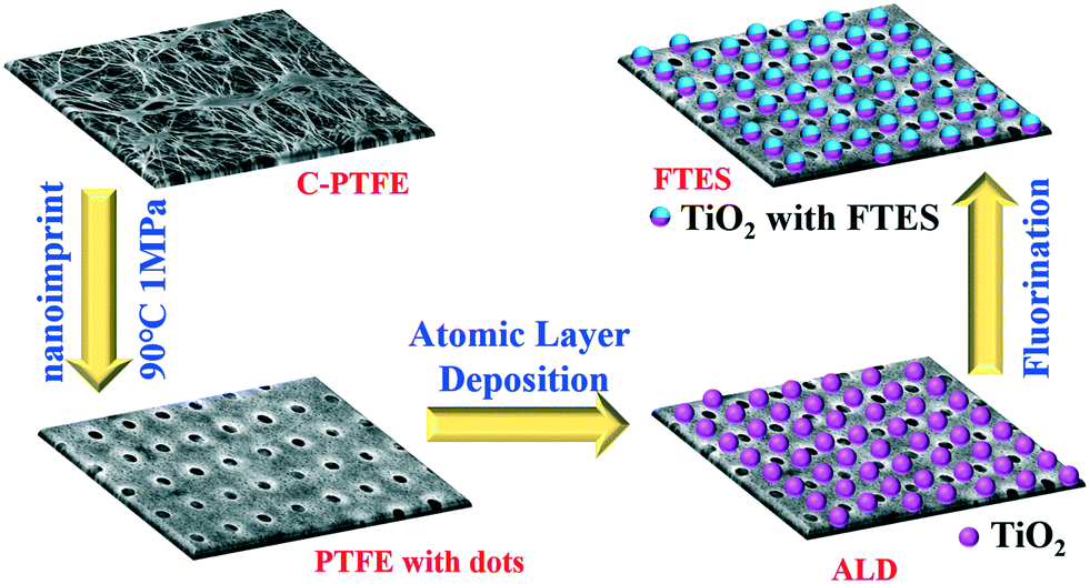 | ||
| Fig. 1 Schematic illustration of design and procedures for fabricating the nanoimprint PTFE membrane with a fluorinated TiO2 deposition layer. | ||
ALD, as a thin film deposition technique, can control the thickness of thin films at the angstrom level based on sequential self-limiting, gas–solid surface reactions.29 From a deposition chemistry perspective, ALD proceeds via two half-reactions where reactants (precursors) are pulsed into a reactor alternately and cycle-wise, while CVD is a continuous process where all reactants are supplied at the same time to grow the film. Another feature of ALD is that it is capable of low-temperature processing30 compared to CVD deposition techniques, thereby being suitable for processing polymeric membranes.
The PTFE membrane was first imparted with a surface pattern with a nanoimprinter (EVG 510, Thallner GmbH, Germany). Specifically, the PVDF membrane was placed on a nickel substrate to ensure an even temperature. The silicon mask used possessed a dot pattern with a circle diameter of 6 μm and a spacing (edge-to-edge) of 6 μm (Fig. S1, ESI†). The silicon mask was cleaned with acetone prior to the fabrication to clean off any debris from previous use. Patterning was carried out at 90 °C with a pressure of 1 MPa for 120 s, and the silicon mask was separated from the membrane samples at 35 °C. The pressure (i.e., piston force) and temperature were closely monitored during the nanoimprint to ensure sufficient surface patterns.
After nanoimprinting, we deposited an ultrathin layer of TiO2 (around 5 nm in thickness) on the dot patterned MD membrane by atomic layer deposition (Fiji F200 ALD, Cambridge Nanotech). Tetrakis(dimethylamino)titanium (Strem Chemicals, Inc., USA), also known as TDMAT, and H2O vapour were used as titanium and oxygen precursors, respectively. An ALD growth cycle of TiO2 deposition consisted of the following steps and parameters: TDMAT pulse 0.1 s, N2 purge 8 s; H2O pulse 60 ms, N2 purge 8 s; deposition temperature at 120 °C. The total cycle of TiO2 deposition was 125, resulting in a TiO2 thickness of around 5 nm. The actual thickness of TiO2 was estimated using a reference silicon wafer with a variable angle spectroscopic ellipsometer (J.A. Woollam M-2000DI).
Utilising the ultrathin film of TiO2 on the dot patterned MD membrane, we further functionalised it with FTES (1H,1H,2H,2H-perfluorooctyltriethoxysilane). Specifically, hydroxylated FTES in toluene was prepared in 50 mL bottles through sonication and vigorous stirring for one hour, respectively. The coating procedure was performed in a glove box over 18 hours to obtain the resultant membrane, which was then washed with toluene and completely dried in an oven prior to use.
2.2 Membrane distillation apparatus and filtration protocol
Direct contact membrane distillation (DCMD) was conducted using a closed-loop bench-scale membrane test apparatus. The membrane cell was made of acrylic plastic to minimize heat loss to the surroundings. Flow channels were engraved in each of two acrylic blocks that made up the feed and permeate semi-cells. Each channel was 0.2 cm deep, 1.5 cm wide, and 1.5 cm long, and the total active membrane area was 2.25 cm2. Temperatures of feed and distillate solutions were controlled with two heaters/chillers (Polyscience, IL, USA), and were continuously recorded using temperature sensors that were inserted at the inlet and outlet of the membrane cell. Both feed and distillate streams were concurrently circulated with two gear pumps. The same crossflow rate of 30 L h−1 (corresponding to the crossflow velocity of 9 cm s−1) was applied to both feed and distillate in order to minimize the pressure difference across the MD membrane. Weight change of the distillate tank was recorded using an electronic balance (Mettler Toledo, OH, USA) with a data logger. All piping used in the DCMD test unit was covered with insulation foam to minimize heat loss.The nanofabricated MD membrane was subjected to both wetting and fouling experiments. Specifically, MD membrane wetting and fouling were simulated with a feed solution containing a 70 g L−1 NaCl solution (simulating seawater brine from reverse osmosis) with either 1 mM sodium dodecyl sulfate (SDS) or 50 mg L−1 humic acid, respectively. In addition, the MD membrane fouling–cleaning cycle was conducted three times in order to examine the fouling reversibility and cleaning efficiency by physical flushing. In the cleaning mode, the humic acid fouled MD membrane was flushed with DI water at a doubled cross flow rate (i.e., 18 cm s−1) for 20 min. After this brief, physical flushing, the fouling filtration resumed.
Feed and distillate volumes of four litres and one litre were used, respectively. The temperature of the inlet feed solution was 60 °C, while that of the distillate inlet stream was 20 °C in all experiments. A new membrane sample was used for each experiment. Permeate mass was recorded with a digital balance continuously. The conductivity of the distillate was measured with a conductivity meter (HQ14d, Hach, CO) every 5 minutes.
2.3 Characterization of the nanofabricated membrane
The nanofabricated MD membrane was comprehensively characterized in order to gain insights into the structure–performance relationship. Scanning electron microscopy (SEM), Fourier transform infrared (FTIR) spectroscopy, X-ray photoelectron spectroscopy (XPS), atomic force microscopy (AFM) and thermogravimetric analysis (TGA) were employed to analyze the morphology and thermal and physicochemical properties of the nanofabricated MD membrane.Surface and cross-section morphology of the completely dried membranes with gold coating was visualized with an EVO MA 10 (Zeiss, Germany) scanning electron microscope at an accelerating voltage of 20 kV. AFM images were acquired with an Asylum Research MFP-3D AFM operating in intermittent contact (“tapping”) mode with a BudgetSensors TAP150Al-G cantilever (fR = 123 kHz, Q = 1745 and k = 2.1 N m−1; with free-air amplitude = 100 nm and feedback set-point = 70%).
To obtain information about the composition and bonding chemistry of the MD membrane surface layer (with penetration depths from 1 to 5 nm thickness), X-ray photoelectron spectroscopy (XPS) analysis was carried out on a monochromatic aluminium Kα X-ray photoelectron spectrometer (Thermo Scientific, MA). Survey spectra were recorded 3 times per sample, over the range of 0∼1000 eV at 1 eV resolution to analyse the elemental composition. Bonding chemistry of the membrane surface layer was analysed by high resolution XPS C1s scan. A spot size of 400 μm was used to scan the region of the C1s binding energy at 20 eV pass energy. Two random spots on the duplicate membrane samples were selected. Excessive charging of samples was minimized using an electron flood gun. High resolution scans had a resolution of 0.1 eV. Calibration for the elemental binding energy was carried out based on the reference for carbon 1 s at 284.6 eV. Data were processed using standard software with a Shirley background and a relative sensitivity factor of 0.278 for C1s peaks.
Membrane surface functional groups were identified using a Fourier transform infrared (FTIR) spectrometer (Thermo Scientific Nicolet 6700) equipped with an ATR accessory consisting of a ZnSe plate (45° angle of incidence). Absorbance spectra were measured with 64 scans of each sample at a spectral resolution of 2 cm−1. Background measurements in air were performed before each membrane sample measurement. ATR-FTIR spectra were collected at two different spots for each membrane sample.
The membrane contact angle (CA) was measured by the sessile drop method using an optical subsystem (Theta Lite 100) integrated with image-processing software. A range of liquids (water, diiodomethane, ethylene glycol and ethanol) were used for contact angle measurements.31
Thermal properties of the nanofabricated MD membrane were quantified by thermogravimetric analysis (TGA) (Discovery TGA thermogravimetric analyser, SDT-Q600, United States) from 50 °C to 700 °C at a heating rate of 10 °C min−1 in N2 atmosphere. The crucible material was platinum. Each sample was dried by purging N2 for 1 min before measurement.
3. Results and discussion
3.1 Characteristics of the nanofabricated MD membrane
A close examination of the circular indentation shows elongated features in the vertical dimension, exhibiting hierarchical morphology. Besides, the AFM images of the TiO2 deposition membrane (Fig. 2E and F) show the spherical hierarchical structure, which might lead to special wettability, thereby being beneficial to MD separation. After fluorination, there is no significant difference with the ALD membrane, only scattered, tiny agglomerated particles could be observed. The FTES membrane still maintained a highly ordered dot pattern with a smoother surface (Fig. 2C).
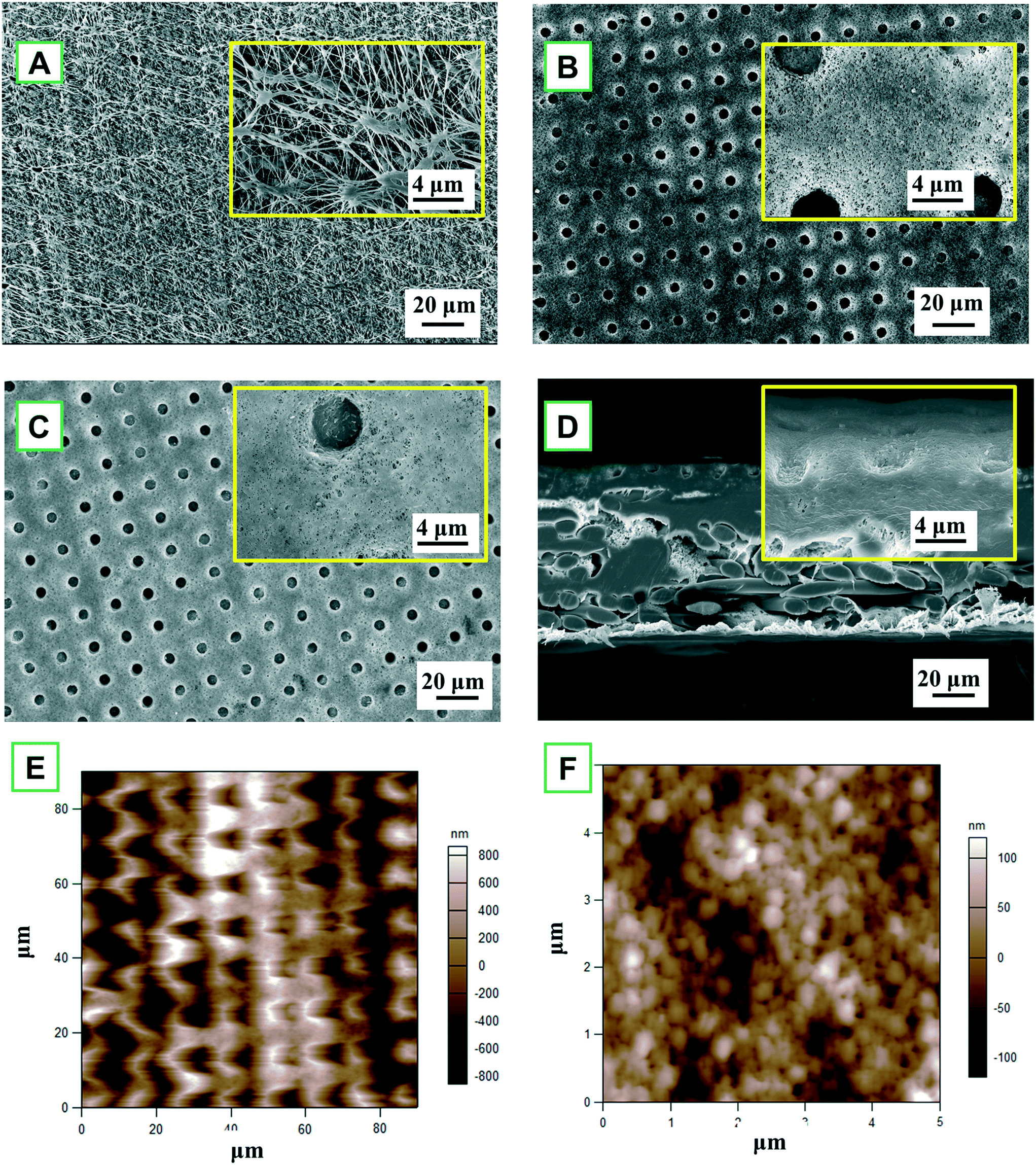 | ||
| Fig. 2 SEM images of the membrane surface: (A) pristine PTFE (C-PTFE); (B) TiO2 atomic layer deposited nanoimprinted membrane (ALD); (C) fluorinated ALD membrane (FTES); (D) cross-section of FTES. Atomic force microscopy (AFM) images of (E) the membrane surface demonstrating the dot pattern and (F) deposition layer of TiO2. | ||
Despite a series of modifications, the PTFE membrane was not compromised as evident in the cross-section of the FTES membrane (Fig. 2D), so the resultant membrane could be expected to have a satisfactory NaCl rejection in the MD filtration. Indeed, the membrane integrity of the modified membrane remains uncompromised, which was evident by a 100% NaCl rejection in the MD filtration. To summarize, after the modification, the nanofabricated PTFE membrane exhibited a periodic, circular surface pattern with a spherical hierarchical structure, and no noticeable difference in the membrane structure was observed.
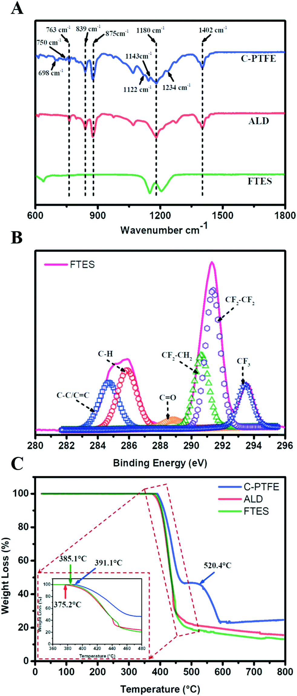 | ||
| Fig. 3 Chemical characterization of C-PTFE and ALD and FTES modified membranes. (A) ATR-FTIR spectra; (B) XPS spectra of C1s of the FTES modified membrane; (C) TGA curves. | ||
The composition of our modified membranes was further studied by thermogravimetric analysis (TGA). As shown in Fig. 3C, the weight of C-PTFE, ALD and FTES remained stable when the temperature was below 350 °C. After that, the three membranes began to lose weight at 375.2 °C (ALD), 385.1 °C (FTES) and 391.1 °C (C-PTFE), respectively. There was a consistent shift of thermal decomposition towards lower temperature of the modified membranes (both ALD- and FTES-modified membranes), which indicates enhancement in thermal stability. Higher residual mass was observed for the ALD modified membrane in comparison with the FTES modified membrane, indicating that the dispersion of TiO2 nanoparticles in the composite membrane resulted in improved thermal properties. Another feature presented in the TGA diagram was that TiO2 deposition on the membrane may catalyse more C-PTFE loss.
3.2 Wetting properties of the nanofabricated MD membrane
The surface wettability of relevant nanofabricated membranes was measured using static water and low surface tension liquid (diiodomethane, ethylene glycol and ethanol) contact angles as shown in Fig. 4. C-PTFE exhibited a high water contact angle of 135°, due to its hydrophobic nature. After the TiO2 deposition, the contact angle decreased to 112°. TiO2 can produce oxygen vacancies on its surface, which could be occupied by water molecules and produce adsorbed –OH groups. Thus, the membrane coated with TiO2 tended to have a more hydrophilic surface, as demonstrated by a lower WCA. By contrast, the fluorination by FTES endowed ALD with an extremely high water contact angle of 155°, thereby rendering a low surface energy as well as manifesting excellent hydrophobicity.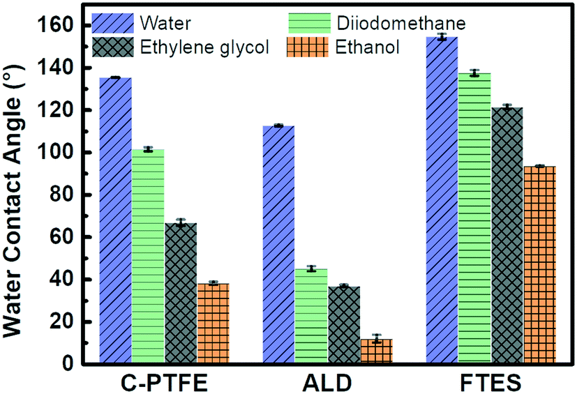 | ||
| Fig. 4 Water and low surface tension liquid (diiodomethane, ethylene glycol and ethanol) contact angles of C-PTFE and ALD and FTES modified membranes. Error bars indicate the standard deviation of three repeated measurements from two membrane samples. | ||
ALD created a hierarchically rough nanostructure. Based on the Wenzel and Cassie theory, the establishment of nano/microscale structures was essential for improving the superhydrophobicity of a membrane. The contact angles of low surface tension liquids had the same tendency as water for similar reasons. As a result, the superhydrophobic surface of FTES is expected to have robust stability for MD applications.
3.3 Nanofabricated MD membrane exhibited anti-wetting behaviour
To further examine the role of the fluorinated, hierarchically rough, nanostructure membrane surface, we compared the wetting behavior of ALD and FTES membranes to the pristine PTFE membrane using saline feed containing 1 mM SDS. The wetting phenomenon was quantified as the increase of permeate conductivity (Fig. 5). It was observed that the permeate conductivity of the pristine PTFE membrane soared sharply at the beginning, indicating the occurrence of membrane wetting. Although the pristine PTFE membrane is intrinsically hydrophobic, a declining trend in the rejection of NaCl over time was observed, which was consistent with membrane wetting during filtration. By contrast, after TiO2 ALD modification, the permeate conductivity maintained stable for 20 hours. We attribute it to its hierarchically rough nanostructure. Despite the relatively low water contact angle, the hierarchically rough nanostructure could create air pockets on the membrane surface,19 thus mitigating membrane wetting. In comparison, the FTES modified membrane was able to sustain the MD performance. The nanofabricated surface achieved by fluorination and the hierarchically rough nanostructure could successfully preserve a metastable Cassie–Baxter state (liquid–air interface) that prevents the membrane from being wetted.32–34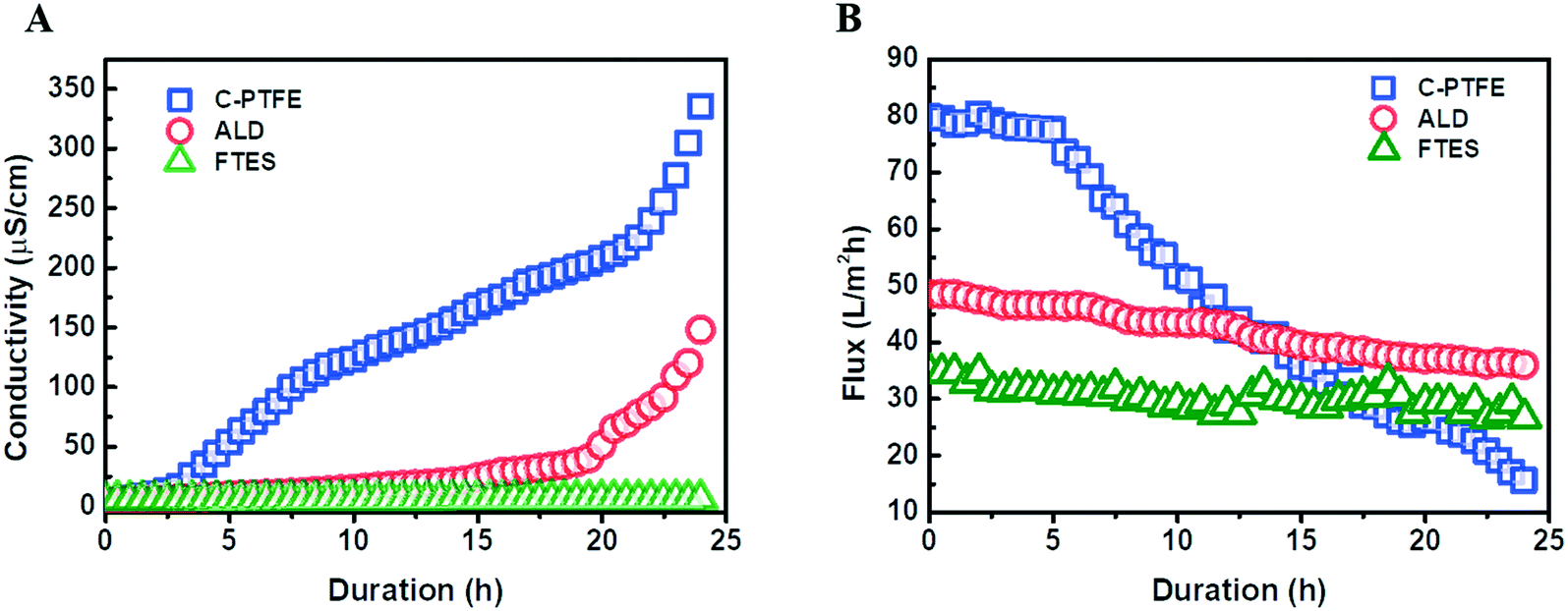 | ||
| Fig. 5 Comparison of the filtration performance of C-PTFE and ALD and FTES modified membranes: (A) permeate conductivity and (B) water flux. | ||
Profiles of water flux during the filtration also confirmed the occurrence of membrane wetting (Fig. 5B). The pristine PTFE was subjected to a rapid flux decline. More importantly, surfactants in the feed can enter the membrane pores with ease, preventing the transfer of vapor across the membrane, while the TiO2 ALD and FTES modified MD membranes could maintain a relatively steady water flux. In addition, it was noteworthy that the water flux of the FTES modified membrane (34 L m−2 h−1) was lower than that of the TiO2 ALD membrane (55 L m−2 h−1). This difference could be attributed to the fact that the increase in the thickness of the MD membrane slightly increased the resistance to water vapour transmission.
3.4 Nanofabricated MD membrane possessed high fouling reversibility
One important hindrance in the deployment of the MD membrane for challenging waste streams is membrane fouling and fouling reversibility after cleaning. The MD membrane possessing a fluorinated hierarchically rough nanostructure membrane surface was tested in three fouling–cleaning cycles where a brief (20 minutes), physical membrane flushing (doubling crossflow velocity) using DI water was carried out as membrane cleaning. A highly satisfactory water flux recovery was observed in the second and third cycles, achieving a water flux recovery of 91.3% and 97.1%, respectively (Fig. 6B). Such high water flux recoveries could be attributed to the nanostructured surface pattern on the MD membrane. A highly ordered periodic, circular surface pattern can potentially minimize the foulant–membrane interaction during the filtration. This high fouling reversibility was consistent with our previous results and recent literature.35–38 Apart from the topological perspective, the fluorinated TiO2 thin film layer on the membrane surface also renders high slip properties (low adhesion) against foulants during filtration. Indeed, the patterned surface with fluorination may alter the foulant deposition from a pinned state to suspended state.38 Similar observations were also reported in gypsum scaling in the MD process with a superhydrophobic micropillared PVDF membrane.39 Both factors contributed to the excellent fouling reversibility, which is vital for the sustainable and robust MD membrane filtration for wastewater treatment.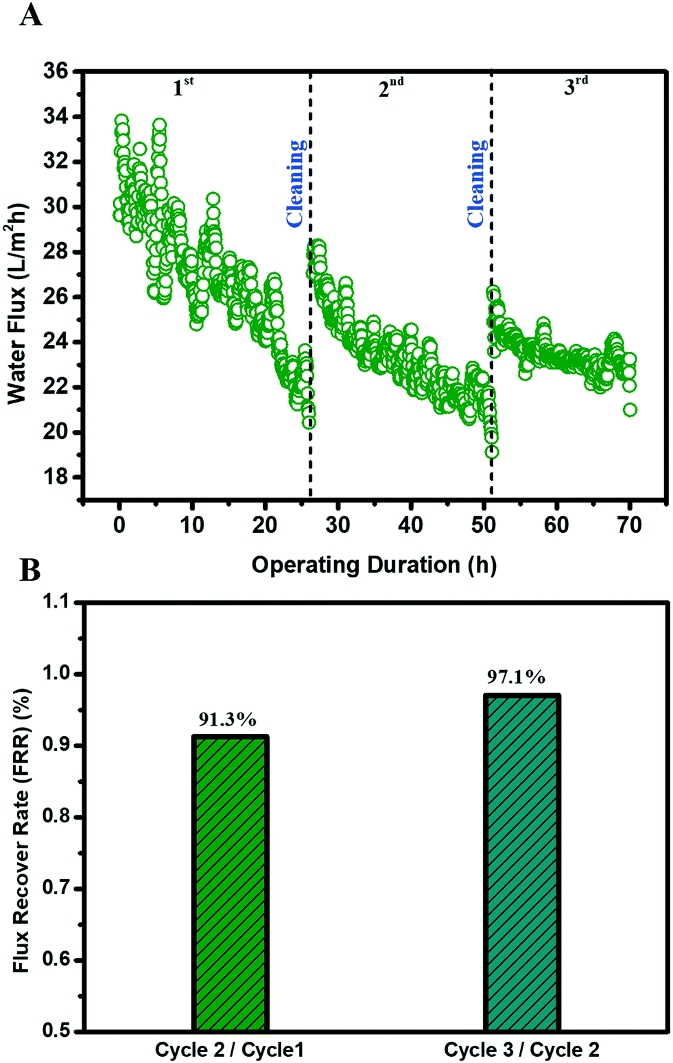 | ||
| Fig. 6 Performance of the FTES modified membrane in membrane distillation after three fouling–cleaning cycles: (A) water flux decline curve; (B) calculated water flux recovery rate after each cycle. The water flux recovery was calculated as the ratio between the initial water fluxes of two consecutive filtration cycles. | ||
4. Conclusion
Results reported here demonstrated a facile and scalable method to fabricate a nanopatterned, omniphobic PTFE membrane via nanoimprinting, atomic layer deposition (ALD), and fluorination for membrane distillation. The nanofabricated MD membrane was imparted with a highly ordered circle pattern and spherical hierarchical rough structure, thereby achieving superhydrophobicity with a water contact angle of 155° and anti-wetting potency for low surface tension liquids. As a result, the nanofabricated MD membrane manifested robust durability with a high and stable water flux of around 34 L m−2 h−1 for more than 24 hours, and near 100% salt rejection in the presence of low surface tension surfactants. More importantly, our modification imparted fouling reversibility, achieving over 91.3% water flux recovery after three fouling–cleaning cycles.Conflicts of interest
There are no conflicts to declare.Acknowledgements
This work was performed in part at the Melbourne Centre for Nanofabrication (MCN) in the Victorian Node of the Australian National Fabrication Facility (ANFF). R. H. acknowledged the support from the China Scholarship Council.References
- Y. Jiang, Environ. Sci. Policy, 2015, 54, 106–125 CrossRef.
- M. Hanna-Attisha, J. LaChance, R. C. Sadler and A. Champney Schnepp, Am. J. Public Health, 2016, 106, 283–290 CrossRef PubMed.
- F. Boltz, N. L. Poff, C. Folke, N. Kete, C. M. Brown, S. S. G. Freeman, J. H. Matthews, A. Martinez and J. Rockström, Water Security, 2019, 8, 100048 CrossRef.
- I. Aselmann and P. Crutzen, J. Atmos. Chem., 1989, 8, 307–358 CrossRef CAS.
- S. K. Hubadillah, M. H. D. Othman, T. Matsuura, M. A. Rahman, J. Jaafar, A. Ismail and S. Z. M. Amin, Sep. Purif. Technol., 2018, 205, 22–31 CrossRef CAS.
- J. Chang, J. Zuo, K.-J. Lu and T.-S. Chung, Desalination, 2019, 449, 16–25 CrossRef CAS.
- J. Guo, B. J. Deka, K.-J. Kim and A. K. An, Desalination, 2019, 468, 114054 CrossRef CAS.
- A. Alkhudhiri, N. Darwish and N. Hilal, Desalination, 2012, 287, 2–18 CrossRef CAS.
- R. D. Gustafson, S. R. Hiibel and A. E. Childress, Desalination, 2018, 448, 49–59 CrossRef CAS.
- X. An, Z. Liu and Y. Hu, Desalination, 2018, 432, 23–31 CrossRef CAS.
- M. Rezaei, D. M. Warsinger, M. C. Duke, T. Matsuura and W. M. Samhaber, Water Res., 2018, 139, 329–352 CrossRef CAS PubMed.
- K. Li, D. Hou, C. Fu, K. Wang and J. Wang, J. Environ. Sci., 2019, 75, 277–288 CrossRef PubMed.
- Y. Shao, M. Han, Y. Wang, G. Li, W. Xiao, X. Li, X. Wu, X. Ruan, X. Yan and G. He, J. Membr. Sci., 2019, 579, 240–252 CrossRef CAS.
- W. Qin, J. Zhang, Z. Xie, D. Ng, Y. Ye, S. R. Gray and M. Xie, Environ. Sci.: Water Res. Technol., 2017, 3, 119–127 RSC.
- L. Dumée, V. Germain, K. Sears, J. Schütz, N. Finn, M. Duke, S. Cerneaux, D. Cornu and S. Gray, J. Membr. Sci., 2011, 376, 241–246 CrossRef.
- M. Tang, D. Hou, C. Ding, K. Wang, D. Wang and J. Wang, Sci. Total Environ., 2019, 696, 133883 CrossRef PubMed.
- H. Li, X. Zi, W. Shi, L. Qin, H. Zhang and X. Qin, Membr. Water Treat., 2019, 10, 287–298 CrossRef PubMed.
- Y. Liao, G. Zheng, J. J. Huang, M. Tian and R. Wang, J. Membr. Sci., 2020, 601, 117962 CrossRef.
- J. Ge, D. Zong, Q. Jin, J. Yu and B. Ding, Adv. Funct. Mater., 2018, 28, 1705051 CrossRef.
- F. Guo, A. Servi, A. Liu, K. K. Gleason and G. C. Rutledge, ACS Appl. Mater. Interfaces, 2015, 7, 8225–8232 CrossRef CAS PubMed.
- Y.-X. Huang, Z. Wang, J. Jin and S. Lin, Environ. Sci. Technol., 2017, 51, 13304–13310 CrossRef CAS PubMed.
- H.-C. Yang, W. Zhong, J. Hou, V. Chen and Z.-K. Xu, J. Membr. Sci., 2017, 523, 1–7 CrossRef CAS.
- Y. Liu, T. Xiao, C. Bao, Y. Fu and X. Yang, J. Membr. Sci., 2018, 563, 298–308 CrossRef CAS.
- Z. Zhu, Z. Liu, L. Zhong, C. Song, W. Shi, F. Cui and W. Wang, J. Membr. Sci., 2018, 563, 602–609 CrossRef CAS.
- J. H. Kim, S. H. Park, M. J. Lee, S. M. Lee, W. H. Lee, K. H. Lee, N. R. Kang, H. J. Jo, J. F. Kim and E. Drioli, Energy Environ. Sci., 2016, 9, 878–884 RSC.
- S. H. Maruf, L. Wang, A. R. Greenberg, J. Pellegrino and Y. Ding, J. Membr. Sci., 2013, 428, 598–607 CrossRef CAS.
- Z. Zhan and Y. Lei, ACS Nano, 2014, 8, 3862–3868 CrossRef CAS PubMed.
- M. Xie, W. Luo and S. R. Gray, Water Res., 2017, 124, 238–243 CrossRef CAS PubMed.
- S. M. George, Chem. Rev., 2010, 110, 111–131 CrossRef CAS PubMed.
- R. L. Puurunen, J. Appl. Phys., 2005, 97, 121301 CrossRef.
- Y. Chul Woo, Y. Chen, L. D. Tijing, S. Phuntsho, T. He, J.-S. Choi, S.-H. Kim and H. Kyong Shon, J. Membr. Sci., 2017, 529, 234–242 CrossRef.
- H. Y. Erbil and C. E. Cansoy, Langmuir, 2009, 25, 14135–14145 CrossRef CAS.
- J. Lee, C. Boo, W.-H. Ryu, A. D. Taylor and M. Elimelech, ACS Appl. Mater. Interfaces, 2016, 8, 11154–11161 CrossRef CAS.
- A. Sudeepthi, L. Yeo and A. Sen, Appl. Phys. Lett., 2020, 116, 093704 CrossRef.
- Y.-J. Won, J. Lee, D.-C. Choi, H. R. Chae, I. Kim, C.-H. Lee and I.-C. Kim, Environ. Sci. Technol., 2012, 46, 11021–11027 CrossRef CAS PubMed.
- D.-C. Choi, S.-Y. Jung, Y.-J. Won, J. H. Jang, J.-W. Lee, H.-R. Chae, J. Lim, K. H. Ahn, S. Lee, J.-H. Kim, P.-K. Park and C.-H. Lee, Environ. Sci. Technol. Lett., 2017, 4, 66–70 CrossRef CAS.
- J. A. Kharraz and A. K. An, J. Membr. Sci., 2020, 595, 117596 CrossRef CAS.
- Z. Xiao, H. Guo, H. He, Y. Liu, X. Li, Y. Zhang, H. Yin, A. V. Volkov and T. He, J. Membr. Sci., 2020, 599, 117819 CrossRef CAS.
- Z. Xiao, Z. Li, H. Guo, Y. Liu, Y. Wang, H. Yin, X. Li, J. Song, L. D. Nghiem and T. He, Desalination, 2019, 466, 36–43 CrossRef CAS.
Footnote |
| † Electronic supplementary information (ESI) available. See DOI: 10.1039/d0ew00100g |
| This journal is © The Royal Society of Chemistry 2020 |