 Open Access Article
Creative Commons Attribution 3.0 Unported Licence
Dendritic silver self-assembly in molten-carbonate membranes for efficient carbon dioxide capture†
Liam A.
McNeil‡
a,
Greg A.
Mutch‡
 a,
Francesco
Iacoviello
 b,
Josh J.
Bailey
 b,
Georgios
Triantafyllou
 a,
Dragos
Neagu
 a,
Thomas S.
Miller
 b,
Evangelos I.
Papaioannou
 a,
Wenting
Hu
 a,
Dan J. L.
Brett
 b,
Paul R.
Shearing
 b and
Ian S.
Metcalfe
 *a
*a
aSchool of Engineering, Newcastle University, Merz Court, Newcastle Upon Tyne NE1 7RU, UK. E-mail: ian.metcalfe@newcastle.ac.uk
bElectrochemical Innovation Lab, Department of Chemical Engineering, UCL, London WC1E 7JE, UK
First published on 29th April 2020
Abstract
Membranes for CO2 capture should offer high permeant fluxes to keep membrane surface area small and material requirements low. Ag-supported, dual-phase, molten-carbonate membranes routinely demonstrate the highest CO2 fluxes in this class of membrane. However, using Ag as a support incurs high cost. Here, the non-equilibrium conditions of permeation were exploited to stimulate the self-assembly of a percolating, dendritic network of Ag from the molten carbonate. Multiple membrane support geometries and Ag incorporation methods were employed, demonstrating the generality of the approach, while X-ray micro-computed tomography confirmed that CO2 and O2 permeation stimulated self-assembly. We report the highest flux of Ag-supported molten-salt membranes to date (1.25 ml min−1 cm−2 at 650 °C) and ultrahigh permeability (9.4 × 10⁻¹¹ mol m−1 s−1 Pa−1), surpassing the permeability requirement for economically-competitive post-combustion CO2 capture, all whilst reducing the membrane-volume-normalised demand for Ag by one order of magnitude.
Broader contextCO2 separation will likely be required for climate change mitigation and process intensification at an unprecedented scale in the future. Processes for CO2 separation include absorption, adsorption and the use of membranes. Membranes are operated under non-equilibrium conditions, as a driving force for e.g. CO2 transport is applied across the membrane. In gas separation, this driving force typically comes from a partial pressure difference between the feed and permeate sides of the membrane. Here, we exploited such non-equilibrium conditions to stimulate the self-assembly of an Ag dendritic network within a dual-phase, supported, molten-salt membrane. The percolating dendrites endowed an inert and low-cost membrane support with electronic conductivity, in turn, enhancing CO2 permeation to a level that surpassed performance metrics required for economically-competitive CO2 separation. The self-assembly occurred in multiple membrane geometries and using different methods of Ag incorporation, which will allow the development of a range of cost-effective and scaleable membrane fabrication routes. By exploiting the non-equilibrium conditions of permeation, typically regarded as challenging for the stability of membrane materials, we have demonstrated a new and general concept for in situ membrane fabrication. |
Introduction
Materials and processes for CO2 separation are widely recognised as increasingly important for climate change mitigation.1–3 Separation of CO2 may be facilitated by sorbents in cyclic sorption/desorption processes,4,5 or continuously by using membrane separation.6 Efficient membrane processes rely on high permeability membrane materials.6,7 Dual-phase, supported, molten-salt membranes are emerging as promising next-generation devices for CO2 separation as they remain functional at operating temperatures where other common membrane materials, e.g. porous inorganics and polymers, lose selectivity and stability, respectively.3 Dual-phase membranes easily surpass the permeability-selectivity trade-off found for the majority of membranes (for polymeric membranes this is known as the Robeson upper bound),8,9 as they offer high permeability due to liquid-like diffusivities in the molten phase, and high selectivity for CO2 due to the chemical specificity of molten carbonate (MC). Such highly-tuned interactions between the permeant of interest and membrane material have been highlighted as one of the key design criteria for new efficient membranes.6 Recent process modelling has demonstrated that dual-phase membranes outperform a commercial absorption process for pre-combustion CO2 capture (where CO2 must be separated from H2). Furthermore, it has been suggested that such membranes will be competitive in post-combustion CO2 capture from coal combustion flue gases (where the membrane feed gas contains CO2, O2 and N2).10 However, there remain a number of challenges to address, specifically, determining permeation mechanisms and increasing separation performance whilst maintaining high temperature stability.3Dual-phase membranes can, in general, be categorised into two classes based on the nature of the solid support; ceramic–carbonate,11–23 and metal–carbonate.24–33 More recently, a combination of the two has been explored.34–36 Ceramic–carbonate membranes are most commonly fabricated using ceramics with oxide-ion conductivity. It is proposed in the literature that ceramic–carbonate membranes exploit reversible reaction (1) at the interface between MC, ceramic support and gas phase:
| CO2(g) + O2−(s) ⇌ CO32−(l) | (1) |
 | (2) |
The first reported metal–carbonate membranes were fabricated from porous stainless-steel infiltrated with MC,30 with CO2 and O2 fluxes stabilising at a level lower than that predicted by reaction (2). The authors suggested that the formation of an electronically-insulating LiFeO2 layer (10−3 S cm−1), through reaction with MC in the presence of O2 at the feed side, lowered the electronic conductivity of the support to a value below the ionic conductivity of MC (100 S cm−1). In this case, and if reaction (2) is sufficient to explain permeation, CO2 and O2 fluxes would be limited by the lower electronic conductivity of the support. To avoid these limitations, Ag-supported, metal–carbonate membranes were later investigated.24,26,29 Ag does not form an oxide layer when in contact with MC at high temperature and offers the highest electronic conductivity of all metals (107 S cm−1). Early Ag-supported dual-phase membranes achieved peak CO2 and O2 fluxes six times higher than stainless-steel membranes, 0.82 and 0.43 ml min−1 cm−2 at 650 °C, respectively, with the 2![[thin space (1/6-em)]](https://www.rsc.org/images/entities/char_2009.gif) :
:![[thin space (1/6-em)]](https://www.rsc.org/images/entities/char_2009.gif) 1 flux ratio imposed by reaction (2) observed.29
1 flux ratio imposed by reaction (2) observed.29
While the initial performance of Ag-supported membranes is very good, it is generally not lasting (e.g. after ∼80 hours of operation at 650 °C, CO2 flux had decreased to ∼0.70 ml min−1 cm−2).29 The high temperature stability issues are thought to be related to poor MC wettability on Ag, and sintering of Ag resulting in a reduction of porosity and ejection of MC.29 Attempts have been made to address stability issues by decreasing the average pore size of the Ag support to increase capillarity,27,33 or by coating the surface of the Ag support with a nano-layer of Al2O3 to improve MC wettability.25,26,28 Alternatively, to limit Ag sintering, a refractory layer of ZrO2 has been deposited.31 It should also be noted that Ag is soluble in MC at the operating temperatures of dual-phase membranes,39,40 through corrosion by MC in the presence of O2,41via reversible reaction (3):
| Ag0(s) ⇌ Ag+(1) + e− | (3) |
In this work we show how such an oxygen cycle, i.e. dissolution and precipitation of Ag, can be exploited advantageously to self-assemble a dendritic Ag network within low-cost Al2O3 dual-phase membrane supports. Self-assembly can be stimulated by the non-equilibrium conditions encountered during membrane operation, ultimately endowing inert membrane supports with electronic conductivity, and in turn, high CO2 and O2 fluxes. The generality of this scaleable and materials-efficient approach has been demonstrated by using multiple methods of Ag incorporation and multiple Al2O3 support geometries. High temperature stability relative to wholly Ag-supported membranes is shown to be greatly improved, due to retained contact between the highly wettable Al2O3 support and MC. Ultimately, through permeation experiments and detailed characterisation of membranes using ex situ X-ray micro-computed tomography, we demonstrate how self-assembling Ag dendrites in MC functionalise membranes so that they easily surpass the separation performance requirements for economically competitive CO2 capture. This is achieved whilst lowering the membrane-volume-normalised requirement for Ag by one order of magnitude.
Results and discussion
The Al2O3 membrane supports used in this work were of pellet and tubular geometry, with randomly-oriented and parallel-pore networks, respectively. These were infiltrated with a ternary eutectic MC mixture (melting point, Tm ≈ 400 °C) to form dual-phase membranes. Ag was added to the support, or MC, before infiltration, characterisation and/or permeation testing. Full procedural detail can be found in the Experimental Methods text, Fig. S1–S4 and Table S1, ESI.†Ag migration in dual-phase membranes
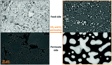
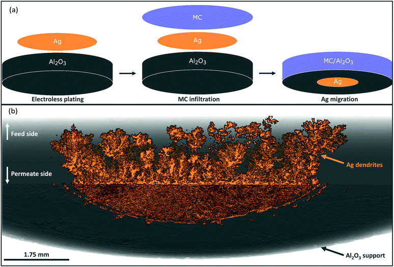
Porous pellet membrane supports were fabricated by isostatic pressing of powdered α-Al2O3 and an organic binder, followed by controlled sintering to form 20 mm diameter (∅) and 1.75 mm thick pellets with a randomly-oriented pore network of average pore diameter ∼200 nm (Fig. S5, ESI†). In the first instance, Ag was introduced to the feed side of Al2O3 pellets via electroless plating (Fig. S1, S2 and Table S1, ESI†). After plating, the pellets had gained a 14 mm ∅, ∼10 μm thick porous layer of metallic Ag (∼17 mg) on the feed side, determined by SEM analysis (Fig. 1a and Fig. S6, ESI†). The permeate side of the plated membrane did not show evidence of Ag deposition, due to masking during electroless plating (Fig. 1a and Fig. S6, ESI†).After infiltration with MC at 450 °C, during which both feed and permeate sides of the membrane were fed with a 50 mol% CO2, 25 mol% O2 and 25 mol% N2 mixture to prevent carbonate decomposition, a permeation experiment was conducted at 650 °C, in a custom-made membrane permeation apparatus (Fig. S4, ESI†). The membrane feed-side inlet was kept the same (50 mol% CO2, 25 mol% O2 and 25 mol% N2 mixture) with Ar fed to the permeate-side inlet, to generate a pCO2 difference between feed and permeate sides, i.e. the driving force for CO2 permeation. After 80 hours of operation a stable flux of 5.0 × 10⁻² ml min−1 cm−2 was achieved, a five-fold improvement on a membrane without Ag deposition (Fig. S7, ESI†).§ SEM-EDX analysis post experiment revealed that the Ag layer on the feed-side had been corroded to a significant extent, with Ag appearing on the permeate side (Fig. 1b, 2a and Fig. S8, ESI†). SEM image analysis revealed that ∼3% of the 17 mg of Ag initially deposited on the feed side had migrated to the permeate-side surface of the membrane (Fig. S9, ESI†). To determine the location and structure of the remaining ∼97% of the initially-deposited Ag, ex situ X-ray micro-computed tomography (micro-CT) analysis was conducted to visualise the internal structure of the membrane (Fig. 2b and Experimental methods, ESI†). Ag was clearly visible on the permeate-side surface, and within the bulk of the porous pellet as a dendritic structure, confined to the central ∼7 mm ∅. The location of the dendrites strongly suggested that Ag migration was driven by gas permeation, given that MC was infiltrated into the pores of the entire 20 mm ∅ Al2O3 pellet, the plated Ag layer was 14 mm ∅, and the active ∅ for permeation was ∼7 mm due to membrane sealing (Fig. 2a and Experimental methods, ESI†). This dendritic network endowed electronic conductivity to the Al2O3 support, evidenced by four-point DC measurements, elaborated upon below.
Impact of Ag incorporation on CO2 and O2 flux
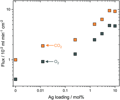
To test the generality of the approach, and reduce the complexity of the synthesis procedure, Ag was mixed as a metallic powder with the ternary eutectic carbonate powder, before infiltration into Al2O3 supports. This removed the requirement for Pd and hydrazine (reagents in electroless plating, ESI†), significantly reduced synthesis time, and allowed more straight-forward control of Ag quantity, all important considerations for scale-up. The Ag powder particles were larger than the average pore diameter of the Al2O3 pellets, so that during carbonate melting and infiltration a layer of the sparingly-soluble Ag particles was deposited on the feed-side surface. Ag mole fraction in MC was varied from 0 to 10 mol% Ag to determine the effect on stable CO2 and O2 fluxes at 650 °C; it was observed that CO2 and O2 fluxes increased with increasing Ag mole fraction (Fig. 3). At 0.25 mol% Ag, CO2 and O2 fluxes were 2.5 × 10⁻² and 1.3 × 10⁻² ml min−1 cm−2, respectively, approximately double that of the 0 mol% Ag membrane, at 1.0 × 10⁻² and 0.4 × 10⁻² ml min−1 cm−2. Within the range studied, a plateau was reached with 6 mol% Ag; fluxes of 9.5 × 10⁻² and 4.8 × 10⁻² ml min−1 cm−2 were achieved for CO2 and O2, respectively. To gain insight into CO2 and O2 transport an Arrhenius plot was constructed using the data from stable flux measurements from 650 to 750 °C with the 6 mol% Ag membrane (Fig. S10, ESI†). CO2 and O2 fluxes had apparent activation energies (Ea) of 30 kJ mol−1, indicating a coupled transport mechanism.¶Ea values were similar to a ZrO2-coated Ag membrane (28 kJ mol−1), operated at similar temperatures to the present membrane (i.e. >650 °C).31 Wholly Ag-supported membranes typically fail at temperatures >650 °C, due to the sintering and wettability issues detailed above, but have Ea values of 60–80 kJ mol−1 at <650 °C.25,26,29,31 Dendritic Ag membranes therefore offer improved high temperature stability, demonstrating stable fluxes at temperatures above that of wholly–Ag membranes.In all of the above cases it is reasonable to assume that the majority of Ag was present as a solid within the membrane at operating conditions, as the Ag loadings far exceeded the solubility limit of Ag in MC at 650 °C.39,40 However, in all cases a small amount of Ag+ was dissolved in MC and therefore, its effect on permeation fluxes needs to be discriminated from Ag in the solid networks. A 1.25 × 10⁻² mol% Ag membrane (Ag quantity below the solubility limit of Ag+ in MC) was prepared by dry impregnation of Ag onto the Al2O3 support before MC infiltration (dry impregnation was used to add such a small quantity accurately) (Fig. S11, ESI†). Dissolved Ag enhanced flux, albeit to a lesser degree than when solid Ag was present, with fluxes of 1.90 × 10⁻² and 0.92 × 10⁻² ml min−1 cm−2 for CO2 and O2, respectively (Fig. 3). Interestingly, all membranes, including the 0 and 1.25 × 10⁻² mol% Ag membranes, exhibited a ∼2![[thin space (1/6-em)]](https://www.rsc.org/images/entities/char_2009.gif) :
:![[thin space (1/6-em)]](https://www.rsc.org/images/entities/char_2009.gif) 1 CO2
1 CO2![[thin space (1/6-em)]](https://www.rsc.org/images/entities/char_2009.gif) :
:![[thin space (1/6-em)]](https://www.rsc.org/images/entities/char_2009.gif) O2 flux ratio. This suggested that the permeation mechanism in this class of membrane is more complex than that suggested by reaction (2), where an electronically-conducting support is implied as necessary for permeation to occur. It may be the case, as previously suggested in relation to an Al2O3-supported, molten-carbonate membrane,22 that this was qualitative evidence for electronic conductivity in MC.42 However, considering the present results, it is most likely that the metallic sealants employed for sealing dual-phase membranes provide transmembrane electronic conductivity. For example, visual analysis of a 0 mol% Ag membrane sealed using a silver ink showed the presence of transmembrane silver deposits and associated impact on flux during permeation experiments (Fig. S12, ESI†). Nonetheless, for our present goal, flux enhancement was most significant in the cases where Ag was present as solid dendrites, indicating that producing electronically-conductive networks is the most efficient route to achieving high transmembrane CO2 flux.
O2 flux ratio. This suggested that the permeation mechanism in this class of membrane is more complex than that suggested by reaction (2), where an electronically-conducting support is implied as necessary for permeation to occur. It may be the case, as previously suggested in relation to an Al2O3-supported, molten-carbonate membrane,22 that this was qualitative evidence for electronic conductivity in MC.42 However, considering the present results, it is most likely that the metallic sealants employed for sealing dual-phase membranes provide transmembrane electronic conductivity. For example, visual analysis of a 0 mol% Ag membrane sealed using a silver ink showed the presence of transmembrane silver deposits and associated impact on flux during permeation experiments (Fig. S12, ESI†). Nonetheless, for our present goal, flux enhancement was most significant in the cases where Ag was present as solid dendrites, indicating that producing electronically-conductive networks is the most efficient route to achieving high transmembrane CO2 flux.
Self-assembly of Ag dendrites
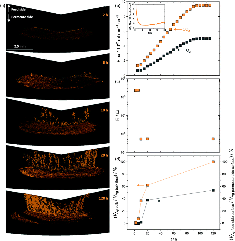
The above data clearly show that CO2 and O2 permeation stimulated Ag-network formation and that dual-phase membranes need not be wholly Ag-supported to exhibit the enhanced fluxes that result from permeation reliant upon electron conduction. The transient flux behaviour consistently observed at the beginning of permeation experiments, before an increase towards the high flux period defined as stable, strongly suggested that Ag dendrite growth occurred during this period.To investigate Ag dendrite formation, five membranes each loaded with the 6 mol% Ag carbonate mixture previously determined as an efficient loading to realise high fluxes, were quenched at various times up to and including stable flux, for micro-CT and four-point DC analysis (Fig. 4). A further five membranes, loaded with varying amounts of Ag (0.0125–6 mol% Ag), were quenched after attaining stable flux (Fig. S13, ESI†). Regardless of the quantity of Ag in the membrane, all membranes displayed a period of low flux during the first 10 hours (Fig. 4b inset and Fig. S13, ESI†), after an initial decrease in CO2 and O2 mole fraction (0–5 hours) due to clearing the permeation chamber of the 50 mol% CO2, 25 mol% O2 and 25 mol% N2 mixture fed to the feed- and permeate-side inlets during carbonate infiltration (Fig. 4b inset). Micro-CT was performed on membranes quenched by rapid cooling after 2, 6 and 10 hours of operation to investigate the low flux period, as well as on membranes from 20 and 120 hours, to investigate the regions of flux increase and stability (Fig. 4a and b). First, after 2 hours of permeation, Ag had already migrated from the feed-side surface to the permeate-side surface (Fig. 4a), in agreement with SEM images (Fig. 1b, Fig. S8 and S9, ESI†), and the initial micro-CT investigation (Fig. 2). After 6 hours, Ag dendrites had started to grow in the direction of the feed side from the permeate side, until they spanned the thickness of the membrane at 10 hours (Fig. 4a). Up to this point, no electronically-conductive Ag path connecting feed and permeate sides appeared to have formed, restricting fluxes to the low values observed during the first 10 hours (Fig. 4b inset). From 10 hours, the dendrites continued to grow, in both thickness and number, offering electronic conductivity across the membrane and increased flux of CO2 and O2viareaction (2) (Fig. 4b). After 90 hours, it was likely that the majority of the initially-deposited Ag had been corroded and redistributed as dendrites within the membrane, leading to flux stabilisation (Fig. 4b). Four-point DC analysis demonstrated that membranes operated for less than 10 hours had an electrical resistance three orders of magnitude higher than membranes operated for 10 hours or more (Fig. 4c), with calculations performed on the micro-CT 3D reconstructions indicating that a substantial quantity of Ag was present within the bulk of the membrane, from 10 hours onwards, with increasing feed to permeate-side connectivity (Fig. 4d).
Ag precipitation in molten salts to form dendritic structures under an electrochemical driving force and when the molten salt is below the Tm of the metal is well-known.43,44 In our case, self-assembly occurred due to the electrochemical gradient established within the membrane as a result of the non-equilibrium conditions of permeation. It is likely that CO32− formation (reaction (2)) consumed electrons produced by Ag dissolution at the high pO2 feed side (reaction (3)). CO32− and Ag+ ions subsequently migrated down their electrochemical potential gradient from feed to permeate side. At the permeate side, CO32− ions decomposed to release electrons, reforming Ag from Ag+, and releasing CO2 and O2 (Fig. 5). Ag first formed at the triple-phase-boundary on the low pO2 permeate side, acting as the nucleation site for continued dendrite formation back towards the feed side. Subsequent electrons released during carbonate decomposition were transported to the tip of the growing dendrite, to recombine with Ag+ from the melt, shortening the diffusional pathway of Ag+, and gradually extending the Ag dendritic network until it spanned the width of the membrane. Such dendritic Ag structures have previously been used to produce electronically-conductive composites, where the unique three-dimensional fractal geometry endowed an ultra-low electrical percolation threshold.45 Our findings demonstrate that the growth of such a dendritic network can also be used to produce self-assembling, electronically-conductive, dual-phase membranes with a substantially lower demand for Ag, elaborated upon below.
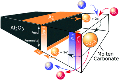 | ||
| Fig. 5 Ag dendrite self-assembly. Dissolution, migration and precipitation of Ag, driven by the non-equilibrium conditions of permeation. | ||
Parallel-pore Ag membranes
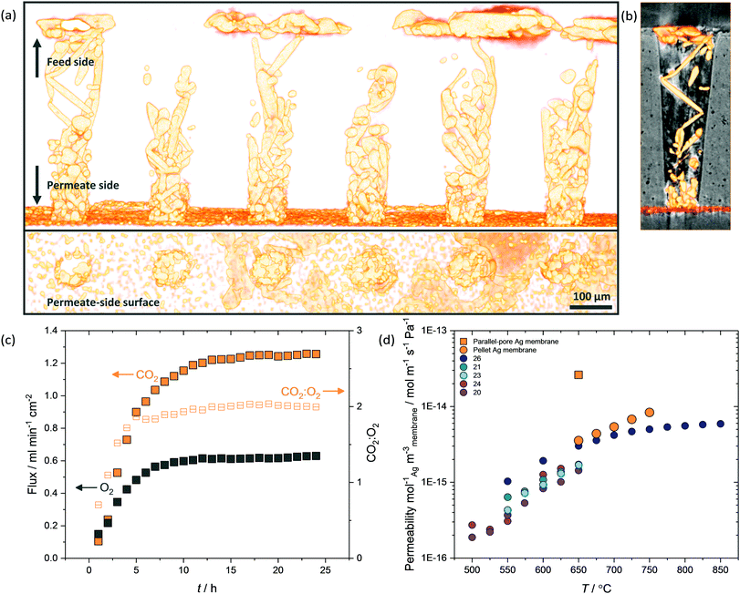
While micro-CT was used successfully to detail the temporal development of the dendritic network within pellet membranes (Fig. 4a), due to the voxel dimension (∼104 nm) being larger than the average pore diameter of the pellet supports (∼102 nm), the precise location and microstructure of Ag could not be accurately determined. Therefore, a tubular membrane was fabricated with 2000 single pores in a 500 μm thick closed end, where the single truncated-cone pores had a feed-side pore diameter of 150 μm and permeate-side pore diameter of 75 μm (Fig. S3, ESI†). These structures were imaged using higher resolution micro-CT, with voxel dimension ∼103 nm, allowing the location and microstructure of Ag within single pores to be identified (Fig. 6 and Fig. S14, S15, ESI†). Again, Ag was clearly visible as a deposited layer on the permeate side (Fig. 6a and b), having migrated from the feed side during a 25-hour permeation experiment with Ag-loaded carbonates (Fig. 6c). With a reduced thickness and tortuosity compared to pellet membranes, the formation of the dendritic Ag structure occurred on a shorter timescale (∼10 h). Growth of dendrites from permeate to feed side was inconsistent, with Ag in selected pores failing to span the thickness of the membrane (Fig. S14, ESI†). Of course, Ag structures beneath the resolution of the micro-CT may still be present, or a small number of connected electronically-conductive networks may have provided preferential fast-transport routes, sufficient to improve overall permeation to the levels observed. However, Ag was invariably found connected to the Al2O3 surface, appearing to track the curvature of the single pores (Fig. 6b and Fig. S15, ESI†). It was also clear that in the majority of single pores, Ag dendrites did not cover the entirety of the pore walls. As portions of the highly wettable Al2O3 surface remained exposed to MC,28 this could explain the ability of dendritic Ag membranes to operate at temperatures above which wholly-Ag membranes routinely fail (Fig. S10, ESI†).The parallel-pore membrane also offered the opportunity to measure permeation in a low-tortuosity and reduced-thickness dendritic Ag membrane. It is known that reducing tortuosity,46 and reducing thickness in dual-phase membranes results in higher fluxes.14 A flux of 1.25 ml min−1 cm−2 at 650 °C was achieved (Fig. 6c), a factor of 13 higher than the pellet membranes and almost two orders of magnitude higher than a parallel-pore membrane control experiment without Ag addition (Fig. S16, ESI†). Peak fluxes for the highest flux Ag-supported membranes in the literature are typically 0.8–0.9 ml min−1 cm−2 at 650 °C,26,29 with the ZrO2-coated Ag membrane achieving 0.9 ml min−1 cm−2, albeit at 850 °C,31 and an Ag membrane with a H2 containing sweep gas reaching 1.3 ml min−1 cm−2 at 700 °C.27![[thin space (1/6-em)]](https://www.rsc.org/images/entities/char_2009.gif) || Ceramic–carbonate membranes have achieved higher still CO2 fluxes employing pre-combustion feed gases (i.e. containing H2 or lacking O2 relative to our experiments) and higher temperatures.20,47
|| Ceramic–carbonate membranes have achieved higher still CO2 fluxes employing pre-combustion feed gases (i.e. containing H2 or lacking O2 relative to our experiments) and higher temperatures.20,47![[thin space (1/6-em)]](https://www.rsc.org/images/entities/char_2009.gif) || We note that, to the best of our knowledge, the CO2 flux reported here at 650 °C is the highest of any ceramic- or metal-carbonate dual-phase membrane reported to date employing a post-combustion feed gas and an Ar sweep gas.31
|| We note that, to the best of our knowledge, the CO2 flux reported here at 650 °C is the highest of any ceramic- or metal-carbonate dual-phase membrane reported to date employing a post-combustion feed gas and an Ar sweep gas.31
Permeability, which normalises the effect of membrane thickness and the driving force for permeation (i.e. pCO2 and pO2 difference between feed and permeate sides), of parallel-pore and pellet membranes was 9.4 × 10⁻¹¹ mol m−1 s−1 Pa−1 and 2.5 × 10⁻¹¹ mol m−1 s−1 Pa−1, respectively, of the same order of magnitude as Ag membranes in the literature.** However, the quantity of Ag used in our membranes was three orders of magnitude lower (e.g. 4 mg compared with ∼4 g used in Xu et al.),29 so that when permeability was normalised for the quantity of Ag used and the volume of membrane, it was clear that dendritic Ag membranes provided ultrahigh permeability at reduced cost (Fig. 6d). While it is possible that laser-drilled membrane supports will not be an economically-viable option for cost-effective scale-up, the principle of reducing the quantity of Ag is clear. A well-controlled pore forming technique such as phase inversion synthesis could be adopted to fabricate parallel-pore membranes at reduced cost, or modular membrane support geometries such as hollow fibres could be used, as Ag network growth appears to be independent of support geometry.
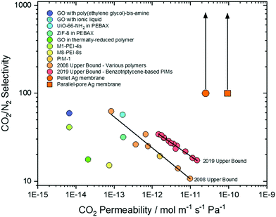
Recently, there has been an increasing recognition of membrane performance targets for post-combustion CO2 capture.48 Depending on specific mode of operation, CO2/N2 selectivity is targeted at 20–150 for pressure-driven operation (pressure ratio 5–15), or >140 when employing a sweep gas.49 This selectivity must be present in membranes with CO2 permeabilities of 10−13–10−12 mol m−1 s−1 Pa−1 to be economically-competitive with existing approaches.49,50 However, membranes generally exhibit a permeability-selectivity trade-off; for polymeric membranes, this is known as the Robeson upper bound,9,51 and as such few membranes have surpassed these targets (Fig. 7). Dual-phase membranes offer outstanding CO2/N2 selectivity (>1000) as the solubility of CO2 in molten carbonate is ∼104 higher than N2.38,52 As N2 is only detected on the permeate side of a dual-phase membrane as the result of a leak, selectivity is routinely calculated based on solubilities alone. Here, we have adopted a more conservative approach and calculated a minimum selectivity based on the limit of detection of our analytical apparatus (Experimental methods text, ESI†). Across all our permeation experiments, we thus determine a minimum CO2/N2 selectivity of ∼100, rising to ∼370 (although we note that this could be as high as >1000) (Fig. 7). Thus, our results surpass the two most recent CO2/N2 Robeson upper bounds,9,51 and a range of state-of-the-art graphene oxide,53,54 mixed-matrix,55–57 SPONG48 and polymer membranes,.9,51,58 Furthermore, dual-phase membranes are amongst a very limited range of membrane materials that can operate at >400 °C, offering exciting new separation opportunities, in e.g. hot flue gases without the need for gas cooling. It is also important to note that dual-phase membranes have recently been shown to self-heal autonomously at high temperature, providing confidence in their durability during operation.59 Finally, knowledge of permeability allows one to define a membrane thickness required to achieve a target permeance (10−7 mol m−2 s−1 Pa−1 for post-combustion CO2 capture).60 The range of state-of-the-art membranes we have selected for comparison require thicknesses of 10−5–10−7 m, whereas dual-phase membranes can achieve the target permeance at 10−4 m thickness. For this reason, the membranes we report here (∼500 μm) are approaching the permeance required for economically-competitive post-combustion CO2 capture, without the need for extreme membrane thinning and the associated costs.
Conclusions
We have prepared dual-phase, supported, molten-salt membranes which exploit self-assembling electronically-conductive dendritic Ag networks. Pellet and tubular membranes, made from low-cost Al2O3, with a range of methods for Ag incorporation were used, demonstrating generality. Through permeation-driven non-equilibrium growth of Ag dendrites, from small quantities of added Ag, low-cost, low-flux membrane materials were transformed into low-cost, high-flux membranes. These membranes achieved the permeance required for cost-effective CO2 capture from post-combustion gas streams (10−7 mol m−2 s−1 Pa−1).60 We reported the highest flux of any metal–carbonate, dual-phase membrane to date (1.25 ml min−1 cm−2 at 650 °C), and ultrahigh permeabilities (10−11 mol m−1 s−1 Pa−1), outperforming the permeability requirement for economically-competitive CO2 capture (10−13–10−12 mol m−1 s−1 Pa−1).49,50 We suggest that non-equilibrium growth of dendritic Ag networks in MC could be employed as a cost-effective strategy to prepare high performance CO2-permeable membranes, with improved high temperature stability. More generally, we propose that the non-equilibrium conditions of membrane permeation, routinely considered as deleterious for long-term stability, can instead be considered as favourable conditions to add advantageous functionality to membranes in situ.Conflicts of interest
There are no conflicts to declare.Acknowledgements
The authors wish to thank Dr Oliver B. Camus at Bath University for conducting mercury intrusion porosimetry measurements and Dr Maggie White at Newcastle University for conducting X-ray diffraction analyses. The research leading to these results has received funding from the European Research Council under the European Union's Seventh Framework Programme (FP/2007-2013)/ERC Grant Agreement Number 320725 and from the Engineering & Physical Sciences Research Council (EPSRC) via grants EP/M01486X/1, EP/P007767/1 and EP/P009050/1. X-ray access was supported by UCL and EPSRC under EP/M028100/1. L. A. M. would like to thank the Newcastle University EPSRC DTP. G. A. M. would like to thank the EPSRC for his Doctoral Prize Fellowship (EP/M50791X/1) and Newcastle University for a Newcastle University Academic Track (NUAcT) Fellowship. T. S. M. would like to thank the EPSRC for his Fellowship (EP/P023851/1). P. R. S. acknowledges the support of the Royal Academy of Engineering (CIET 1718/59). Data supporting this publication is available under a Creative Commons Attribution 4.0 International license, see DOI: 10.25405/data.ncl.9608369.Notes and references
- N. MacDowell, N. Florin, A. Buchard, J. Hallett, A. Galindo, G. Jackson, C. S. Adjiman, C. K. Williams, N. Shah and P. Fennell, Energy Environ. Sci., 2010, 3, 1645 RSC.
- M. E. Boot-Handford, J. C. Abanades, E. J. Anthony, M. J. Blunt, S. Brandani, N. Mac Dowell, J. R. Fernández, M.-C. Ferrari, R. Gross, J. P. Hallett, R. S. Haszeldine, P. Heptonstall, A. Lyngfelt, Z. Makuch, E. Mangano, R. T. J. Porter, M. Pourkashanian, G. T. Rochelle, N. Shah, J. G. Yao and P. S. Fennell, Energy Environ. Sci., 2014, 7, 130 RSC.
- M. Bui, C. S. Adjiman, A. Bardow, E. J. Anthony, A. Boston, S. Brown, P. S. Fennell, S. Fuss, A. Galindo, L. A. Hackett, H. J. Herzog, G. Jackson, J. Kemper, S. Krevor, G. C. Maitland, M. Matuszewski, I. S. Metcalfe, C. Petit, G. Puxty, J. Reimer, D. M. Reiner, E. S. Rubin, S. A. Scott, N. Shah, B. Smit, J. P. M. Trusler, P. Webley, J. Wilcox and N. MacDowell, Energy Environ. Sci., 2018, 11, 1062–1176 RSC.
- G. T. Rochelle, Science, 2009, 325, 1652–1654 CrossRef CAS PubMed.
- J. Blamey, E. J. Anthony, J. Wang and P. S. Fennell, Prog. Energy Combust. Sci., 2010, 36, 260–279 CrossRef CAS.
- H. B. Park, J. Kamcev, L. M. Robeson, M. Elimelech and B. D. Freeman, Science, 2017, 356, 1138–1148 CrossRef PubMed.
- S. Wang, X. Li, H. Wu, Z. Tian, Q. Xin, G. He, D. Peng, S. Chen, Y. Yin, Z. Jiang and M. D. Guiver, Energy Environ. Sci., 2016, 9, 1863–1890 RSC.
- L. M. Robeson, J. Membr. Sci., 1991, 62, 165–185 CrossRef CAS.
- L. M. Robeson, J. Membr. Sci., 2008, 320, 390–400 CrossRef CAS.
- R. Anantharaman, T. Peters, W. Xing and M. Fontaine, Faraday Discuss., 2016, 192, 251–269 RSC.
- X. Dong, J. Ortiz Landeros and Y. S. Lin, Chem. Commun., 2013, 49, 9654–9656 RSC.
- Z. Rui, M. Anderson, Y. Li and Y. S. Lin, J. Membr. Sci., 2012, 417–418, 174–182 CrossRef CAS.
- T. T. Norton and Y. S. Lin, Solid State Ionics, 2014, 263, 172–179 CrossRef CAS.
- M. Anderson and Y. S. Lin, J. Membr. Sci., 2010, 357, 122–129 CrossRef CAS.
- H. Ahn, D. Kim, V. M. A. Melgar, J. Kim, M. R. Othman, H. V. P. Nguyen, J. Han and S. P. Yoon, J. Ind. Eng. Chem., 2014, 20, 6–11 Search PubMed.
- O. Ovalle-Encinia, H. Pfeiffer and J. Ortiz-Landeros, J. Membr. Sci., 2018, 547, 11–18 CrossRef CAS.
- T. T. Norton, B. Lu and Y. S. Lin, J. Membr. Sci., 2014, 467, 244–252 CrossRef CAS.
- M. Zuo, S. Zhuang, X. Tan, B. Meng, N. Yang and S. Liu, J. Membr. Sci., 2014, 458, 58–65 CrossRef CAS.
- J. Tong, L. Zhang, M. Han and K. Huang, J. Membr. Sci., 2015, 477, 1–6 CrossRef CAS.
- L. Zhang, N. Xu, X. Li, S. Wang, K. Huang, W. H. Harris and W. K. S. Chiu, Energy Environ. Sci., 2012, 5, 8310–8317 RSC.
- L. Zhang, X. Li, S. Wang, K. G. Romito and K. Huang, Electrochem. Commun., 2011, 13, 554–557 CrossRef CAS.
- J. L. Wade, C. Lee, A. C. West and K. S. Lackner, J. Membr. Sci., 2011, 369, 20–29 CrossRef CAS.
- T. T. Norton, J. Ortiz-Landeros and Y. S. Lin, Ind. Eng. Chem. Res., 2014, 53, 2432–2440 CrossRef CAS.
- L. Zhang, Y. Gong, K. S. Brinkman, T. Wei, S. Wang and K. Huang, J. Membr. Sci., 2014, 455, 162–167 CrossRef CAS.
- L. Zhang, Y. Gong, J. Yaggie, S. Wang, K. Romito and K. Huang, J. Membr. Sci., 2014, 453, 36–41 CrossRef CAS.
- J. J. Tong, X. L. Lei, J. Fang, M. F. Han and K. Huang, J. Mater. Chem. A, 2016, 4, 1828–1837 RSC.
- J. Fang, J. Tong and K. Huang, J. Membr. Sci., 2016, 505, 225–230 CrossRef CAS.
- J. Tong, F. Si, L. Zhang and J. Fang, Chem. Commun., 2015, 51, 2936–2938 RSC.
- N. Xu, X. Li, M. A. Franks, H. Zhao and K. Huang, J. Membr. Sci., 2012, 401–402, 190–194 CrossRef CAS.
- S. J. Chung, J. H. Park, D. Li, J. I. Ida, I. Kumakiri and J. Y. S. Lin, Ind. Eng. Chem. Res., 2005, 44, 7999–8006 CrossRef CAS.
- P. Zhang, J. Tong, Y. Jee and K. Huang, Chem. Commun., 2016, 52, 9817–9820 RSC.
- L. Zhang, J. Tong, Y. Gong, M. Han, S. Wang and K. Huang, J. Membr. Sci., 2014, 468, 373–379 CrossRef CAS.
- J. Fang, N. Xu, T. Yang, P. Zhang, J. Tong and K. Huang, J. Membr. Sci., 2017, 523, 439–445 CrossRef CAS.
- P. Zhang, J. Tong and K. Huang, ACS Sustainable Chem. Eng., 2018, 6, 14162–14169 CrossRef CAS.
- P. Zhang, J. Tong and K. Huang, J. Mater. Chem. A, 2017, 5, 12769–12773 RSC.
- O. Ovalle-Encinia, H. Pfeiffer and J. Ortiz-Landeros, Ind. Eng. Chem. Res., 2018, 57, 9261–9268 CrossRef CAS.
- Z. Rui, M. Anderson, Y. S. Lin and Y. Li, J. Membr. Sci., 2009, 345, 110–118 CrossRef CAS.
- G. A. Mutch, L. Qu, G. Triantafyllou, W. Xing, M.-L. Fontaine and I. S. Metcalfe, J. Mater. Chem. A, 2019, 7, 12951–12973 RSC.
- G. J. Janz, A. Conte and E. Neuenschwander, Corrosion, 1963, 19, 292–294 CrossRef.
- G. J. Janz, E. Neuenschwander and A. Conte, Corros. Sci., 1963, 3, 177–180 CrossRef CAS.
- J. M. Fisher and P. S. Bennett, J. Mater. Sci., 1991, 26, 749–755 CrossRef CAS.
- H. Nafe, ECS J. Solid State Sci. Technol., 2014, 3, 23–29 CrossRef.
- T. B. Reddy, J. Electrochem. Soc., 1966, 113, 117–123 CrossRef CAS.
- A. M. S. El Din and G. Wranglén, Electrochim. Acta, 1962, 7, 79–90 CrossRef CAS.
- C. Yang, X. Cui, Z. Zhang, S. W. Chiang, W. Lin, H. Duan, J. Li, F. Kang and C. P. Wong, Nat. Commun., 2015, 6, 1–10 CAS.
- J. Ortiz-Landeros, T. Norton and Y. S. Lin, Chem. Eng. Sci., 2013, 104, 891–898 CrossRef CAS.
- X. Dong, H. C. Wu and Y. S. Lin, J. Membr. Sci., 2018, 564, 73–81 CrossRef CAS.
- G. He, S. Huang, L. F. Villalobos, J. Zhao, M. Mensi, E. Oveisi, M. Rezaei and K. V. Agrawal, Energy Environ. Sci., 2019, 12, 3305–3312 RSC.
- K. Ramasubramanian, H. Verweij and W. S. Winston Ho, J. Membr. Sci., 2012, 421–422, 299–310 CrossRef CAS.
- N. Bryan, E. Lasseuguette, M. Van Dalen, N. Permogorov, A. Amieiro, S. Brandani and M. C. Ferrari, Energy Procedia, 2014, 63, 160–166 CrossRef CAS.
- B. Comesana-Gandara, J. Chen, C. G. Bezzu, M. Carta, I. Rose, M.-C. Ferrari, E. Esposito, A. Fuoco, N. B. McKeown and J. C. Jansen, Energy Environ. Sci., 2019, 12, 2733–2740 RSC.
- M. R. Cerón, L. S. Lai, A. Amiri, M. Monte, S. Katta, J. C. Kelly, M. A. Worsley, M. D. Merrill, S. Kim and P. G. Campbell, J. Membr. Sci., 2018, 567, 191–198 CrossRef.
- S. Wang, Y. Xie, G. He, Q. Xin, J. Zhang, L. Yang, Y. Li, H. Wu, Y. Zhang, M. D. Guiver and Z. Jiang, Angew. Chem., Int. Ed., 2017, 56, 14246–14251 CrossRef CAS PubMed.
- M. Karunakaran, L. F. Villalobos, M. Kumar, R. Shevate, F. H. Akhtar and K. V. Peinemann, J. Mater. Chem. A, 2017, 5, 649–656 RSC.
- P. D. Sutrisna, J. Hou, M. Y. Zulkifli, H. Li, Y. Zhang, W. Liang, D. M. D’Alessandro and V. Chen, J. Mater. Chem. A, 2018, 6, 918–931 RSC.
- P. D. Sutrisna, J. Hou, H. Li, Y. Zhang and V. Chen, J. Membr. Sci., 2017, 524, 266–279 CrossRef CAS.
- S. Kim, J. Hou, Y. Wang, R. Ou, G. P. Simon, J. G. Seong, Y. M. Lee and H. Wang, J. Mater. Chem. A, 2018, 6, 7668–7674 RSC.
- A. K. Sekizkardes, V. A. Kusuma, G. Dahe, E. A. Roth, L. J. Hill, A. Marti, M. Macala, S. R. Venna and D. Hopkinson, Chem. Commun., 2016, 52, 11768–11771 RSC.
- M. Kazakli, G. A. Mutch, L. Qu, G. Triantafyllou and I. S. Metcalfe, J. Membr. Sci., 2020, 600, 117855 CrossRef CAS.
- T. C. Merkel, H. Lin, X. Wei and R. Baker, J. Membr. Sci., 2010, 359, 126–139 CrossRef CAS.
Footnotes |
| † Electronic supplementary information (ESI) available. See DOI: 10.1039/c9ee03497h |
| ‡ These authors contributed equally to this work. |
| § Throughout, we define stable flux as a minimum of 4 hours where the mean flux varied less than ±3%. |
| ¶ In this case, the apparent activation energy corresponds to all processes that result in a transmembrane flux of CO2 or O2, i.e. surface reactions and bulk transport processes. Although technically incorrect, as the reported activation energy represents multiple processes, the values are useful for comparing our results with other membranes in the literature. |
| || We note that reported fluxes are often the highest flux achieved during the first ∼10–20 hours of a permeation experiment, with stable fluxes at ∼80 hours some ∼10% lower than the values highlighted here. |
| ** Note that we do not account for the driving force of O2 in our calculation of permeability (and therefore permeance) as this is the procedure widely adopted with Ag-supported membranes, thus allowing us to compare. |
| This journal is © The Royal Society of Chemistry 2020 |

