
The large piezoelectricity and high power density of a 3D-printed multilayer copolymer in a rugby ball-structured mechanical energy harvester†
Xiaoting
Yuan
 a,
Xiangyu
Gao
a,
Jikun
Yang
a,
Xinyi
Shen
a,
Zhanmiao
Li
a,
Sujian
You
a,
Zehuan
Wang
a and
Shuxiang
Dong
*ab
a,
Xiangyu
Gao
a,
Jikun
Yang
a,
Xinyi
Shen
a,
Zhanmiao
Li
a,
Sujian
You
a,
Zehuan
Wang
a and
Shuxiang
Dong
*ab
aDepartment of Materials Science and Engineering College of Engineering, Peking University, Beijing, China. E-mail: sxdong@pku.edu.cn
bBeijing Key Laboratory for Magnetoelectric Materials and Devices (BKL-MEMD), China
First published on 15th October 2019
Abstract
Piezoelectric polymers are characterized by their flexibility and ease of processing into shapes, however, their piezoelectric coefficients, such as d33, are quite low (∼24 pC N−1). Here we report a 3D-printed multilayer β-phase PVDF-TrFE copolymer which does not require high temperature annealing or complicated transfer processes and exhibits a much higher effective piezoelectric coefficient (d33 ∼ 130 pC N−1 for six 10 μm layers). In order to confirm its high power density, a rugby ball-shaped energy harvester, which operates via a flextensional mechanism, was prepared using the multilayer copolymer. The experimental results show that it can produce a peak voltage of ∼88.62 Vpp and a current of 353 μA, which are 2.2 and 10 times those of a single-layer PVDF-TrFE harvester, respectively, under a pressure of 0.046 MPa. Notably, its peak output power density was as high as 16.4 mW cm−2 (according to Ppeak = (VpeakIshort)/2); while at a load of 568 kΩ, it was still 5.81 mW cm−2. The proposed copolymer processing method and flextensional mechanism in a rugby ball configuration show great potential for future micro-energy development in flexible, wearable electronic devices and wireless sensor networks.
Broader contextA 3D-printed rugby ball-structured PVDF-TrFE piezoelectric energy harvester (PEH) with high power density is investigated based on the large piezoelectric coefficient of the multilayer composite film and the enhanced electromechanical coupling that results from a flextensional mechanism. The PEH with its novel structure is prepared through a simple and low-cost process, and has flexible and mechanically durable properties with a very high power density. We demonstrate that the rugby ball PEH can produce a peak voltage of ∼88.62 Vpp and a current of 353 μA, which are respectively 2.2 and 10 times those of a single-layer flat PVDF-TrFE harvester, under a pressure of 0.046 MPa in the low-frequency range. Notably, the peak output power density (16.4 mW cm−2) from the rugby ball harvester is almost 22 times higher than that of a flat type PEH. |
1. Introduction
Harvesting energy from natural sources such as mechanical strain,1 motion,2 light,3 heat,4 and magnetic fields5 has become a research hotspot in the fields of wearable, self-powered (medical) electronics, and wireless sensor networks (WSNs) in the Internet of Things (IoT).6–8 For energy harvesting from mechanical strain and motion, conventional methods have employed piezoelectric,9 electrostatic,10 photovoltaic,11 pyroelectric12 and electromagnetic mechanisms,13 individually or coupled together;14 however, as a typical self-powered and self-sensing wearable device, a piezoelectric energy harvester (PEH) shows advantages such as a simple structure, miniaturization, and a high energy density.15,16 In the piezoelectric material family, poly(vinylidene fluoride) (PVDF) and its copolymer PVDF-TrFE are new functional polymer materials.17 PVDF is polymerized from its monomer and gives three common crystal structures indexed as the α, β and γ phases,18 of which only the β phase displays excellent pyroelectric and ferroelectric properties.19 The copolymer PVDF-TrFE gives a β phase with high crystallinity without special treatment which results in a larger piezoelectric response than that of PVDF.20 In comparison to the traditional brittle inorganic ceramic Pb(Zr,Ti)O3 (PZT) and the single crystal Pb(Mg1/3Nb2/3)O3–PbTiO3 (PMN–PT), PVDF and its copolymer are flexible, have small dielectric constants, small acoustic impedances, wide response frequencies, stable chemical properties, and can be easily processed into any shape;21,22 therefore, they are more suitable for applications in wearable electronics. However, their piezoelectric performances relative to those of inorganic piezoelectric ceramics or single crystals is still very poor.23It is known that the performances of energy harvesters are mainly determined by the piezoelectric material used and its structure. In order to improve output power, researchers have made great efforts to specify material precessions and structural designs. For example, Wang et al. designed a wind energy harvester with PVDF leaves in a veined structure. It was found that under a wind blowing at ∼11 m s−1, the induced maximum output voltage was ∼1.1 V, which was 4–6 times higher than that obtained without using a veined structure.24 Cha et al. prepared a nanoporous PVDF nanogenerator array via a lithography, template-assisted preparation method for harvesting sonic energy. They obtained a power density of 0.17 mW cm−3, with the output voltage and current enhanced to 5.2 times and 6 times, respectively, those of a film (bulk) PVDF generator under the same sonic radiation.25 Maurya et al.26 mounted a piezoelectric PVDF cantilever inside a tire, and the rotational motion induced a power output of 580 μW at the speed of 112 km h−1 (∼16 Hz).
A multilayer ceramic capacitor (MLCC) has unique advantages for electric charge storage, but it is brittle and easily damaged under an external impacting force. In order to improve the energy harvesting performance, some researchers have designed flexible, multilayer composite energy harvesters. For example, Moon Hyun Chung et al. reported a piezoelectric nanogenerator (PENG) made by spin-coating a PVDF-TrFE layer-by-layer (LbL) composited multilayer, and they observed a 5-fold enhancement of the closed-circuit output current (∼100 nA) in comparison with that of a single-layer PENG.27 Lee et al. simply bonded four PVDF layers together with epoxy resin to prepare a four-layer PVDF composite cantilever for harvesting sound pressure energy, and found that under sound wave radiation (15 Pa, ∼118 dB) at 850 Hz, the induced peak power was 0.19 μW (0.12 μW cm−2) which was 2.3 times higher than that of a single layer.28 Most studies on multilayer energy harvesters involve simply folding or bonding multiple monolayers together with epoxy resin, however, this influences the stress transfer and the induced charge. In addition, other preparation methods have been reported for enhancing the piezoelectric performance of PVDF and its copolymers. For instance, Bhavanasi et al. reported a bilayer film of PVDF-TrFE and graphene oxide (GO) (by simply casting the GO solution onto the PVDF-TrFE film) that exhibited a doubled energy harvesting performance (∼4.41 μW cm−2) compared to that of the poled PVDF-TrFE film alone (∼1.77 μW cm−2).29 Woo-Suk Jung et al.30 designed a curved multilayer generator. The peak output voltage and current density reached ∼155 V and 25 μA cm−2, respectively, when it was taped to a finger. The instantaneous output power was estimated to be ∼3.9 mW cm−2, which is the highest value ever reported from a piezoelectric polymer generator or harvester.
Apart from the material itself, the structural design is important for effectively harvesting force/strain or mechanical vibration energy. Typical structural designs include a cantilever type,31 curved composite,32 wave shape,33 and spring,34–36 which show much better energy harvesting performances than a simple flat structure. Therefore, it is necessary to develop an improved method to prepare multilayer PVDF and its copolymer, and design a structure that is more effective for harvesting energy.
Since 2012, triboelectric nanogenerators (TENGs) have also entered the field of self-powered sensing devices.37–39 For example, Z. L. Wang's group40 designed a spring TENG for harvesting vibration energy, and its peak power density at an acceleration amplitude of 23 m s−2 was found to be 4.5 μW cm−2. Recently, Wang's group41 reported a TENG composed of a cam and a movable frame for harvesting mechanical energy within a running tire, and the generated open-circuit voltage and short-circuit current at a rotational speed of 60 rpm were around 200 Vpp and 2.9 μA, respectively. The typical characteristics of a TENG include high output voltage but low output current. Since the triboelectric effect is a result of two materials in physical contact, especially in contact-sliding mode, TENGs often have poor durability.42
In our work, we introduce a simple and low-cost 3D-printing process for preparing a flexible PVDF-TrFE copolymer with multiple thin layers, and a polydimethylsiloxane (PDMS) rugby ball structure. The fabrication method allowed us to achieve an enhanced piezoelectric effect without the need for high temperature annealing or complicated transfer processes. A 3D-printing process is a simple deposition method that is well-suited to printing multiple uniform thin layers of PVDF-TrFE or metal films on various substrates without causing any mechanical damage. By optimizing the viscosity of the functional inks, the air pressure, frequency, speed and other parameters of the printing, multiple thin layers of PVDF-TrFE copolymer with excellent performance could be prepared. In order to confirm the high power density of the polymer, we further designed and fabricated a rugby ball-structured lightweight, and flexible piezoelectric energy harvester (PEH) made from the multilayer PVDF-TrFE polymer and PDMS. We found that the induced output power under dynamic pressing was significantly enhanced in comparison to those for conventional PEHs due to the enhanced electromechanical coupling.
2. Design of the rugby ball-structured PEH
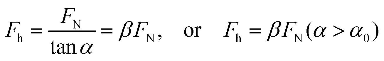
In order to harvest the mechanical energy more effectively, we designed a 3D-printed, soft, rugby ball-structured energy harvester. It uses a flextensional mechanism to convert an applied normal force into an amplified horizontal force which acts on a PVDF-TrFE multilayer composite that is wrapped around the PDMS rugby ball. Fig. 1a schematically illustrates the structure of the rugby ball-shaped energy harvester which has a ring-shaped, inactive shell exterior. The inset in Fig. 1a further illustrates the amplified configuration of the PVDF-TrFE composite film that contains six thin layers with alternate positive and negative polarizations along the radial direction. These thin layers are electrically connected in parallel to produce a large charge under pressure. Fig. 1b schematically represents the multilayer structure of the β-phase PVDF-TrFE and Ag electrode at the molecular level.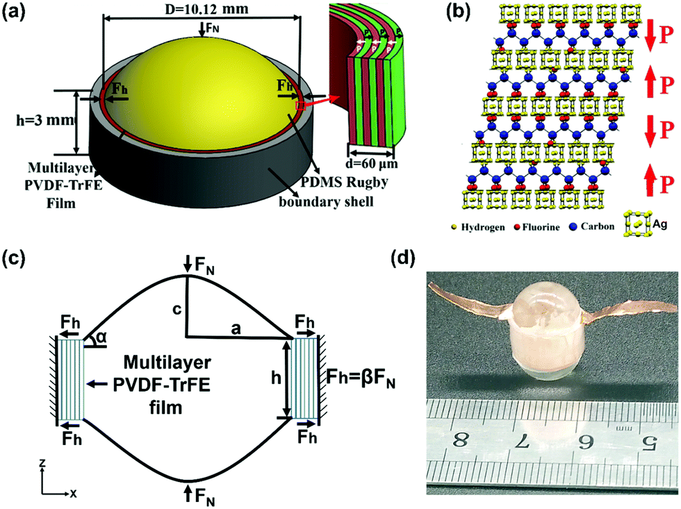 | ||
| Fig. 1 (a) A schematic diagram of the PEH. (b) A schematic diagram of the multilayer PVDF-TrFE and internal electrode layer at the molecular level; P indicates the electric polarization direction. (c) Mechanical structure analysis. (d) A photograph of the 3D-printed rugby ball-shaped multilayer PVDF-TrFE PEH. | ||
Fig. 1c illustrates the flextensional mechanism utilized by the rugby ball structure. When one pair of normal forces FN are applied to the top and bottom of the PDMS polymer rugby ball, a large elastic deformation occurs in the radial direction that converts the normal force FN into a horizontal force Fh. In turn, this acts on the PVDF-TrFE composite film with a force amplification factor β.43,44 In Fig. 1c, a is the equatorial radius (along the x-axis), c is the polar radius (along the z-axis) of the polymer rugby ball, and h is the height of the cylinder (which is also the width of the multilayer PVDF-TrFE belt). According to the diagram of component forces shown in Fig. 1c, Fh can be approximately estimated as:
 | (1) |
![[thin space (1/6-em)]](https://www.rsc.org/images/entities/char_2009.gif) α, and α (≈arctan(c/a)) is the arc angle of the rugby ball relative to the horizontal plane. In eqn (1), α0 is a threshold value, and eqn (1) is valid only when α > α0 due to the soft character of the elastomer. Fig. 2a shows the calculated values of the force amplification factor β as a function of α using eqn (1), and also the simulated values obtained with the finite element method (FEM). It is clear that the theoretically predicted values from eqn (1) coincide well with the simulated values from FEM when α > α0. Furthermore, it is interesting to note that the rugby ball structure can produce a force amplification effect only in the arc angle range of 2.3° < α < 45°, and β exhibits the maximum value around α0 (= 11.3°). Beyond the given range, the rugby ball structure loses the force amplification effect.
α, and α (≈arctan(c/a)) is the arc angle of the rugby ball relative to the horizontal plane. In eqn (1), α0 is a threshold value, and eqn (1) is valid only when α > α0 due to the soft character of the elastomer. Fig. 2a shows the calculated values of the force amplification factor β as a function of α using eqn (1), and also the simulated values obtained with the finite element method (FEM). It is clear that the theoretically predicted values from eqn (1) coincide well with the simulated values from FEM when α > α0. Furthermore, it is interesting to note that the rugby ball structure can produce a force amplification effect only in the arc angle range of 2.3° < α < 45°, and β exhibits the maximum value around α0 (= 11.3°). Beyond the given range, the rugby ball structure loses the force amplification effect.
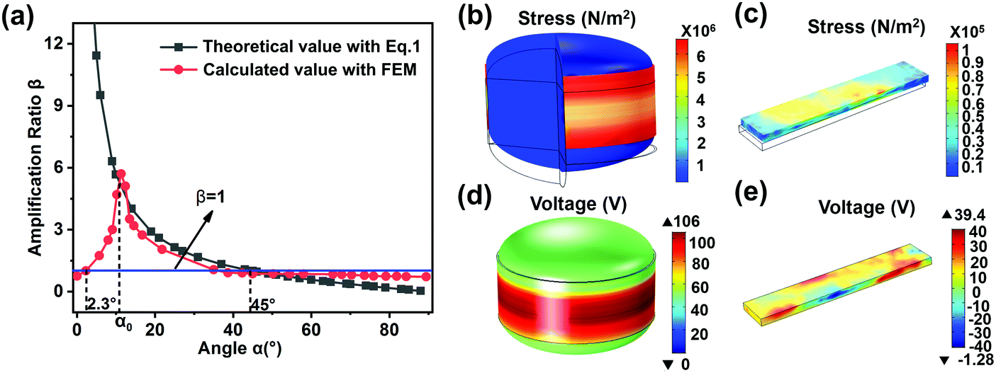 | ||
| Fig. 2 (a) The relationship between the force amplification ratio β and angle α. (b) and (d) The stress and voltage distributions on the N-layer PVDF-TrFE belt in the rugby ball structure under a normal pressure of 0.046 MPa. (c) and (e) The stress and voltage distributions on a flat PVDF-TrFE N-layer belt under a normal pressure of 0.046 MPa. | ||
FEM was also used to analyse the static mechanics and the induced electric potential of the N-layer (where N is the number of layers) PVDF-TrFE in the rugby ball-structured PEH under a given load, as shown in Fig. 2b and d. As a comparison, the stress and voltage distributions of one flat PVDF-TrFE N-layer under the same normal pressure are also presented, as shown in Fig. 2c and e. It is clear that both the stress and the induced electric potential in the rugby ball structure are much higher than those in the flat structure. In addition, the structure parameter h of the rugby ball structure influences the stress distribution on the PVDF-TrFE belt, so affecting the output voltage of the PEH. An optimum h can be found according to FEM simulation, as shown in Fig. S1(a) (ESI†).
According to the piezoelectric equation, the external stress T3 that induces an electric displacement (charge per unit area) D33 is
| D33 = d33T3 | (2) |
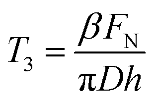 is the stress induced by Fh along the radial direction (where D is the diameter of the rugby ball and h is the width of each layer). According to eqn (2), the induced charge ΔQ, the corresponding short-circuit current peak Ipeak and the open output voltage peak Vpeak from one film under the impact force FN at low-frequency are given as:
| ΔQ = βFNd33 | (3) |
 | (4) |
 | (5) |
As for an N-layer PVDF-TrFE composite film, the induced charge ΔQ and current Ipeak under FN will be enhanced by N times, but Vpeak will remain unchanged because C0 is also increased by N times. The peak output power Ppeak can be estimated as
 | (6) |
Obviously, in comparison to a flat piezoelectric polymer, the output voltage from N-layer PVDF-TrFE in the rugby ball-shaped PEH will be enhanced by (i) the flextensional effect β of the elastic rugby ball; and (ii) N times the piezoelectric effect of the N-layer composite film. In addition, it is found that a suitable α or smaller h will help to enhance the output voltage and power due to a higher compressive stress for the same normal force FN. This phenomenon can be confirmed by using FEM. Fig. 2b and c indicate the compressive stress distributions in PVDF-TrFE polymers in the rugby ball structure and in flat PEHs under an applied normal pressure of 0.046 MPa; it is found that the compressive force transmitted from the rugby ball structure due to the flextensional mechanism is much higher than that transmitted in the flat PEH. Correspondingly, the output voltage ratio of the rugby ball to the flat PEHs is over 2, as shown in Fig. 2d and e.
3. Results and discussion
3.1 Properties of the PVDF-TrFE film and energy harvester
First, we characterized the phase structure, capacitance and ferroelectric performances of monolayer PVDF-TrFE film. The X-ray diffraction pattern in Fig. 3a indicates the crystal structure of the polarized PVDF-TrFE film. The prominent peak located at 2θ = 19.8° comes from the sum of the diffractions from the (110) and (200) planes.45 The result demonstrates that most of the crystalline phases have been transformed into the β phase; see the inset in Fig. 3a.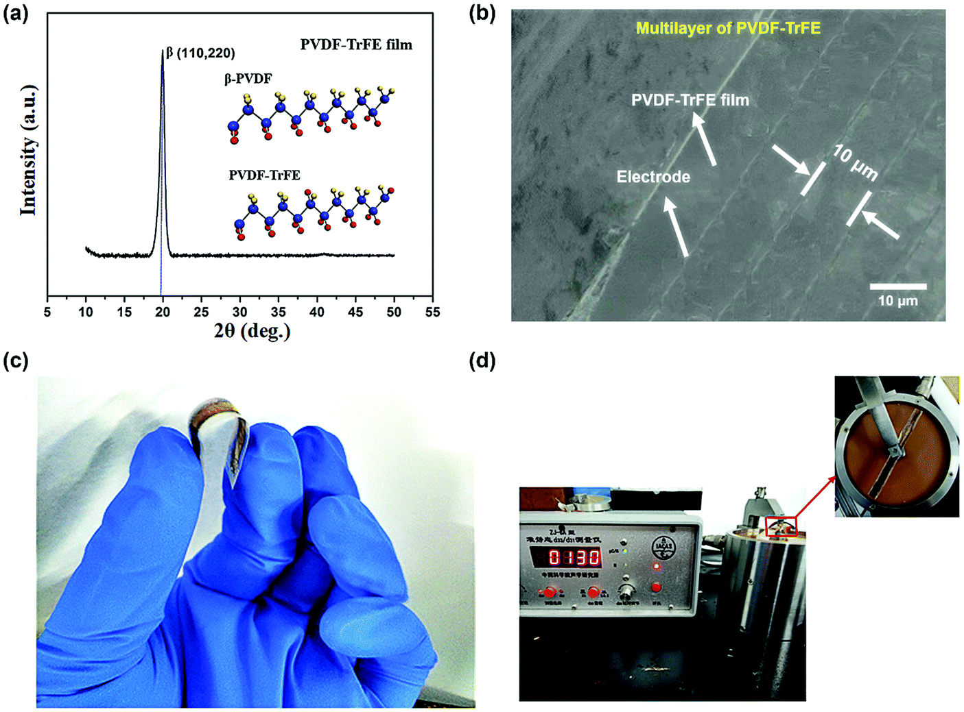 | ||
| Fig. 3 (a) X-ray diffraction pattern of PVDF-TrFE film. (b) An SEM image of a cross section of the six-layer PVDF-TrFE film. (c) A photograph showing that the PVDF-TrFE PEH is flexible, bendable, and rollable. (d) The piezoelectric coefficient d33 of the multilayer PVDF-TrFE PEH. | ||
Fig. 3b shows a cross section of the prepared 3D-printed six-layer PVDF-TrFE polymer composite, which includes the internal electrode. It can be clearly seen that the six-layer film composite and the internal electrode are combined well together. The thickness of each single PVDF-TrFE layer prepared by 3D printing is uniform (∼10 μm), indicating that this is a simple method for the preparation of the PVDF-TrFE films.
Fig. 3c shows a photograph of the prepared six-layer PVDF-TrFE polymer sample and Fig. 3d shows the measurement of its piezoelectric coefficient d33. Piezoelectricity as high as 130 pC N−1 was observed from the sample, which is six times higher than that from a single PVDF-TrFE film (d33 ∼ 22 pC N−1). The piezoelectric coefficient d33 of α-PVDF is only 3 pC N−1, and more test data from different samples are shown in Fig. S2 (ESI†). The measured capacitance of the six-layer composite is about 4.6 nF, which is also six times that of a single layer because the six layers are electrically connected in parallel. The fabricated multilayer PVDF-TrFE polymer is flexible, bendable, and even rollable, and it can be easily integrated into flexible electronic devices as a self-powered system. Mechanical tests on the PVDF-TrFE single film and multilayer composite film are shown in Fig. S3 (ESI†). Fig. S3 (ESI†) shows that the tensile strengths of the single layer and the multilayer are very similar, and although the hardness of the multilayer film is slightly increased, it does not affect the flexibility of the composite film.
3.2 Energy harvesting performance
We investigated the vibration energy harvesting performance of the prepared 3D-printed multilayer PVDF-TrFE rugby ball PEH (6-layer RPEH) using a dynamic compression platform. A dynamic compressive stress was applied to the top of the rugby ball PEH and the induced voltage signal could be observed with an oscilloscope. As a comparison, a conventional single-layer flat PEH (1-layer FPEH), a six-layer flat PEH (6-layer FPEH), a single-layer α-PVDF flat PEH (1-layer α-FPEH) and a single-layer rugby ball-structured PEH (1-layer RPEH) were prepared, and their vibration energy harvesting performances were also investigated.Fig. S4 (ESI†) shows a photograph of the test setup. Fig. 4a–d exhibit the measured voltage responses of the four types of energy harvester under a compression stress of 0.046 MPa in the low-frequency range of 1–10 Hz. The induced open-circuit voltages from the 6-layer RPEH, 1-layer RPEH, 6-layer FPEH and 1-layer FPEH were ∼88.62, 79.05, 43.54, and 39.59 Vpp (peak to peak voltage) at 10 Hz, respectively. The insets in Fig. 4 also illustrate these PEHs. It should be noted that the maximum output voltage from the 6-layer RPEH (as shown in Fig. 4d) is 2.2 times higher than that of the conventional 1-layer FPEH under the same pressure (as shown in Fig. 4a). This phenomenon can be attributed to the force amplification effect of the rugby ball structure, as explained previously. The output voltages of 1- and 6-layer RPEHs, and 1 and 6-layer FPEHs were next measured with respect to varying pressures. Fig. 4e shows the applied pressure versus the output voltage of the PEHs in the range of 0.005 to 0.05 MPa. It is clear that the output voltages increase almost linearly with increased applied pressure in the measured range. The output voltages of the 1-layer α-FPEH are also shown in Fig. 4e. These indicate that the output voltage is the result of the piezoelectric effect rather than the triboelectric effect. Again, RPEHs show higher output voltages due to the flextensional mechanism of the rugby ball structure. To test the cycling stability, a 10 Hz dynamic pressure (0.046 MPa) was applied to the 6-layer RPEH for over 10000 cycles, and the corresponding output voltages were recorded by a digital oscilloscope as shown in Fig. 4f. It is clear that the output voltage is almost constant, and that no performance degradation is observed even after 10000 cycles. In addition, as depicted in Fig. S5(a) and (b) (ESI†), the Ag electrode film retains its mechanical integrity after 10000 vibration cycles. Also, there is no damage seen in the cross section of the composite film after 10000 cycles, as shown in Fig. S5(c) (ESI†), indicating that the rugby ball structure design of the piezoelectric energy harvester is rational and reliable.
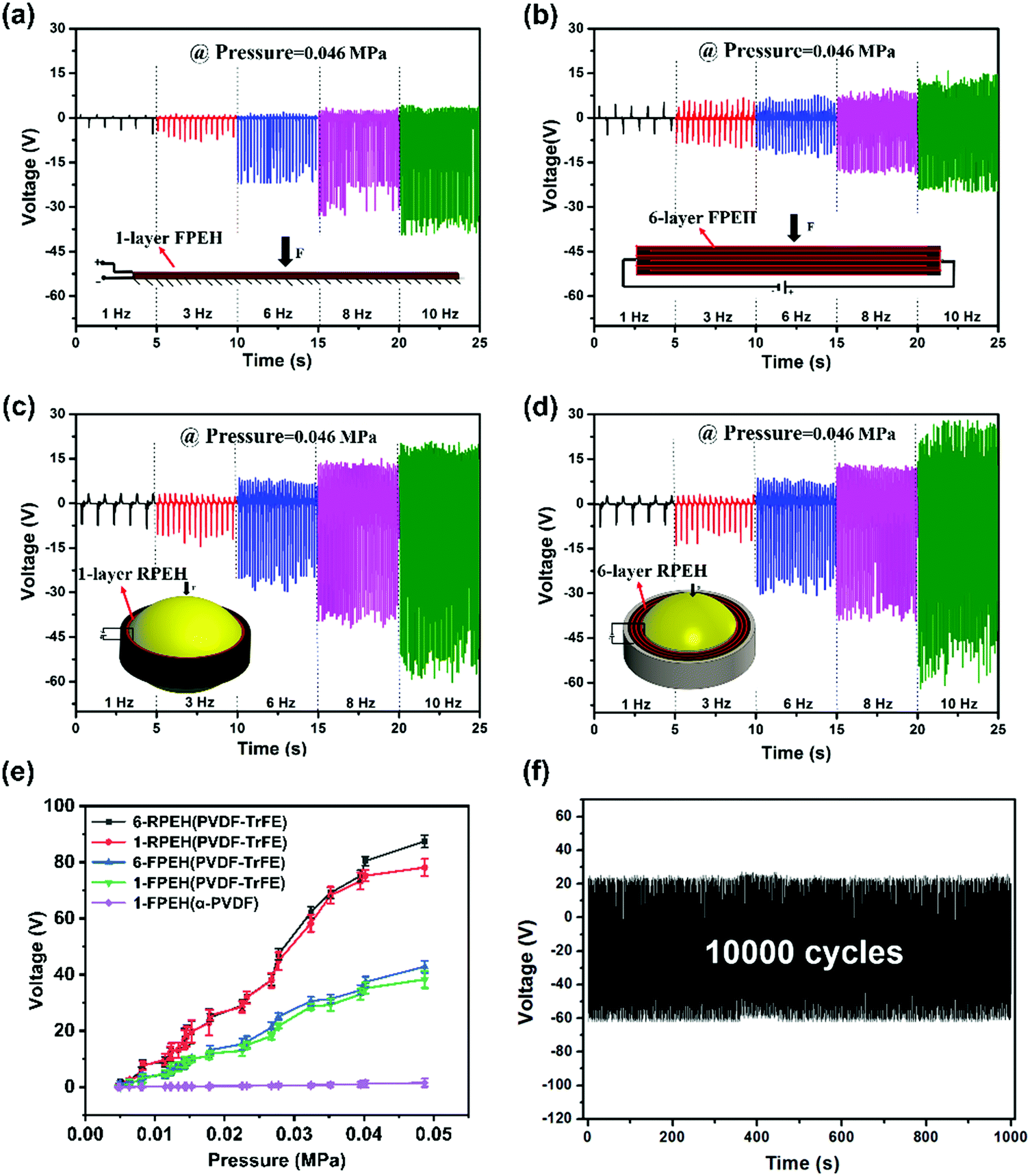 | ||
| Fig. 4 The open circuit voltage measured when a uniform compressive stress is applied at the top of (a) 1-layer FPEH, (b) 6-layer FPEH, (c) 1-layer RPEH and (d) 6-layer RPEH. (e) The output voltages of 1-layer RPEH, 6-layer RPEH, 1-layer FPEH, 6-layer FPEH and 1-layer α-FPEH as a function of dynamic pressure at 10 Hz. (f) The cycling stability of 6-layer RPEH under a dynamic pressure of 0.046 MPa at 10 Hz. | ||
Fig. 5a illustrates the output current as a function of load resistance for 1-, 2-, 4-, and 6-layer FPEHs and 1-, 2-, 4-, and 6-layer RPEHs under a dynamic compression stress of 0.046 MPa at 3.5 Hz. It was found that the 6-layer RPEH produced a maximum peak current of 353.17 μA, which is five and 10 times higher than those of a multilayer flat type harvester and a single layer flat type harvester, respectively. Note that the 1-layer RPEH has a slightly higher current output at a lower resistance in comparison to the 6-layer FPEH. This phenomenon can be attributed to the flextensional mechanism of the rugby ball configuration, which enhances the output voltage of the 1-layer RPEH to two times that of the 6-layer FPEH.
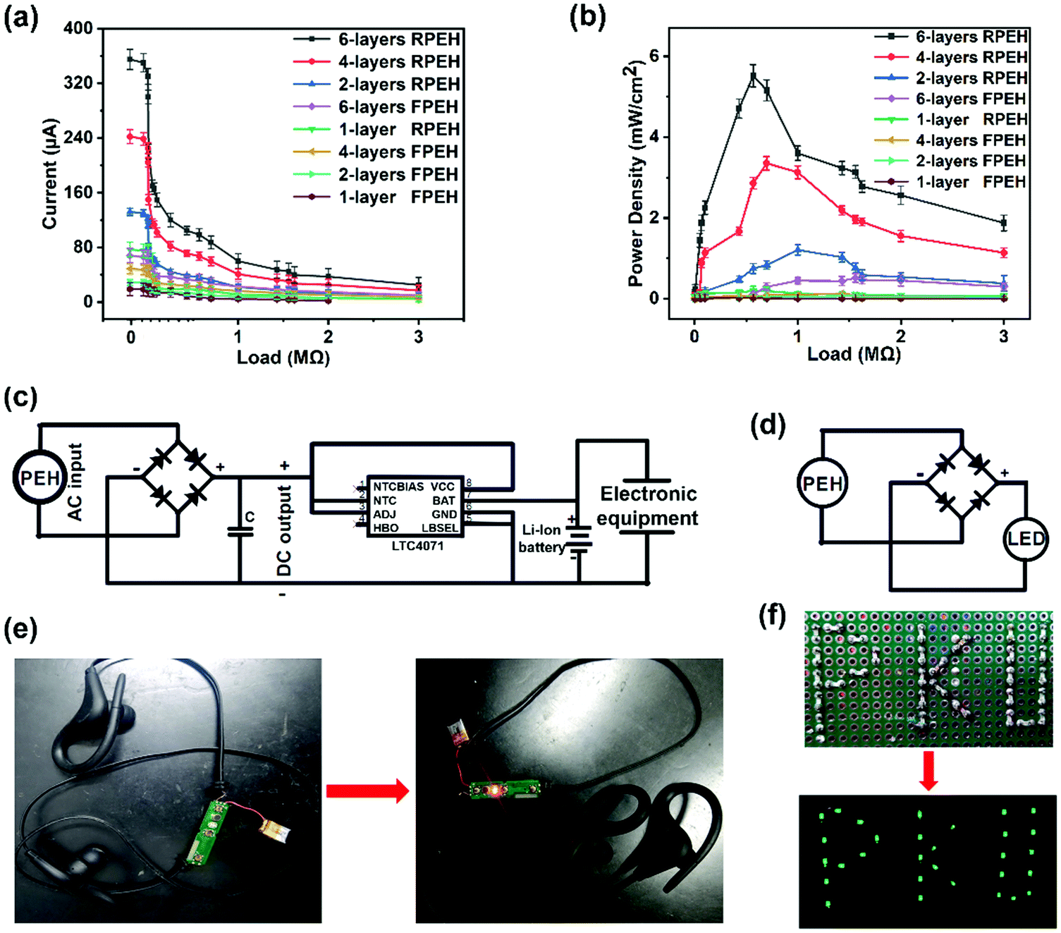 | ||
| Fig. 5 The output current (a) and power (b) of 1-, 2-, 4-, and 6-layer FPEHs, and 1-, 2-, 4-, and 6-layer RPEHs, under a dynamic compression stress of 0.046 MPa at 3.5 Hz. (c) Circuit for converting the AC voltage harvested from vibrations into DC power for charging a Li-ion battery. (d) A schematic diagram of the circuit for instantly lighting LEDs in the absence of an external capacitor. (e) A photo of the charged battery powering Bluetooth earphones. (f) 30 LEDs can be lit directly with the 6-layer RPEH. | ||
The output power of the PVDF-TrFE PEH was extracted by measuring the voltage across a load resistance ranging from 991 Ω to 3 MΩ. Fig. 5b indicates the output power as a function of load resistance for 1-, 2-, 4-, and 6-layer FPEHs and 1-, 2-, 4-, and 6-layer RPEHs at 3.5 Hz. The maximum power output of 5.81 mW cm−2 was observed from the 6-layer RPEH at a load of 568 kΩ, which is 100 times higher than that of the 1-layer FPEH. Again, the enhanced power output should be attributed to the force amplification effect of the rugby ball structure, the enhanced piezoelectric effect and the increased capacitance of the multilayer polymer, and therefore, the lower internal impedance. From Fig. 5a and b, it is apparent that the output current and power density are proportional to the number of PVDF-TrFE layers under a dynamic compression stress of 0.046 MPa at 3.5 Hz. However, our experimental results show that if the number of 3D-printed multilayers is over eight or 10, there is a risk of a short circuit. This phenomenon may be related to Rayleigh instability occurring in the 3D ink-jetting process during printing.46
To investigate the practical application of the 6-layer RPEH device, a new circuit that converts the AC voltage harvested from vibrations into DC power was designed for charging one Li-ion battery (see Fig. 5c). The fully charged battery was used to drive a Bluetooth earphone, confirming that the 6-layer RPEH device worked effectively (see Fig. 5e). The 6-layer RPEH device could also drive the direct lighting of 30 commercial green LEDs (integrated in series) without using an external capacitor (see Fig. 5d, f, and Video (ESI†) for the details).
In addition, a calculation of the peak output power from the open circuit voltage and short-circuit current (Ppeak = VpeakIpeak/2) gave a value of 16.4 mW for the 6-layer RPEH, while for the 1-layer FPEH and 6-layer FPEH, the power outputs were only 0.7 mW and 1.5 mW, respectively. According to eqn (4)–(6), the calculated peak voltage and current for the 6-layer RPEH are 94.7 V and 444.6 μA, respectively; correspondingly, the theoretical peak output power Ppeak is 19.7 mW. Clearly, the theoretically estimated values coincide well with the experimental results.
Table 1 summarizes the output voltage, current and power of the four structures. The maximum power density values were calculated according to Ppeak = VopenIshort/2. Again, it is clear that the 3D-printed 6-layer RPEH has a much higher output power, which shows that apart from the design of the multilayer PVDF-TrFE composite film itself, the flextensional mechanism induced significant force amplification in the rugby ball structure.
| Maximum voltage output [V] | Maximum current output [μA] | Maximum power density output [mW cm−2] | |
|---|---|---|---|
| 1-FPEH | 39.59 | 35.6 | 0.74 |
| 6-FPEH | 43.54 | 66.00 | 1.51 |
| 1-RPEH | 79.05 | 120.00 | 5.00 |
| 6-RPEH | 88.62 | 353.18 | 16.41 |
Table 2 presents a comparison of the power density values obtained in this work with those in other typically reported data. It is clear that the output power density (mW cm−2) of the 6-layer RPEH is much higher than those of previous reported devices.30,47–65
With the fast development of wearable electronics, wireless sensor networks (WSNs), and the Internet of Things (IoT), self-powered sensors and micro-energy harvesting from the environment is becoming critical and important, because it is becoming impossible to replace large quantities of batteries frequently after long lifetime operations. The power required to operate each sensor is typically in the micro-watt to milli-watt range, and the proposed RPEH basically meets these power needs. Furthermore, the proposed 3D-printing method used for the copolymer multilayer is an advanced technology which enables fast fabrication of micro-energy harvesters without environmental pollution. The proposed RPEH with its rugby ball-configuration design and its fabrication method show great potential for future micro-energy development due to the high power density achieved.
4. Conclusions
In summary, we found that a 3D-printed multilayer β-phase PVDF-TrFE copolymer (with six 10 μm-layers) has a large piezoelectric coefficient (d33 ∼ 130 pC N−1). A rugby ball-structured PEH made of the multilayer PVDF-TrFE composite film exhibits a high peak output voltage of 88.6 Vpp under a pressure of 0.046 MPa in the low-frequency range, which is approximately two times that of a flat single-layer PVDF-TrFE PEH. Moreover, the peak output power density (16.41 mW cm−2) from the rugby ball harvester is almost 22 times higher than that of a flat type PEH. The enhanced output voltage and power of the rugby ball-structured multilayer PEH can be attributed to the large piezoelectric coefficient of the multilayer composite film and the force amplification factor of the rugby ball structure due to a flextensional mechanism – a more effective method of transducing mechanical energy into electric energy.5. Experimental section
5.1 Materials
A mixture of acetone (Sigma-Aldrich) and dimethyl sulfoxide (DMSO; Sigma-Aldrich; 65 g L−1) was chosen as the solvent system for the polyvinylidene fluoride copolymer (PVDF-TrFE; JieChuang YongTai, Tianjin, China; mole ratio = 70:30). Dimethyl sulfoxide was added as a β-phase initiating agent and solvent, but it has a boiling point of about 189 °C. Acetone has a low boiling point (∼56 °C) but PVDF-TrFE has low solubility in acetone. The ratio of DMSO:acetone was experimentally optimized to 60:40 to facilitate quick shape retention during printing. The right print viscosity was obtained by optimizing the PVDF-TrFE mass fraction. PVDF-TrFE (0.77 g) was sonicated with DMSO (4.158 g), and acetone (2.772 g), with stirring for 5 h at 30 °C, to form a solution of ≈10 wt% for printing. To print the conductive layers, we used commercially available silver ink (CON-FX750; NANO TOP, Beijing, China) with a solid content of 70 wt%. The polymer rugby ball was made of polydimethylsiloxane (PDMS; SYLGARD 184). The PDMS main agent and curing agent were mixed in the ratio of 25:1.
5.2 Fabrication of the rugby ball-structured multilayer PEH
3D printing technology has been widely used for programme-controlled additional material manufacturing. With a 3D-printing method, it is possible to obtain even films and a precise structure in the desired area. In this work, PVDF-TrFE films, metal films and the PDMS rugby ball were all prepared by using a self-made double nozzle 3D piezoelectric printer (Peking University and Heidstar, Beijing, China). The nozzle and the motion platform were both piezoelectric. The motion platform had a high resolution (∼50 nm), and the droplet size could be accurate to 1 μm. A Nordson-EFD PICOMV-100 piezoelectric nozzle and a direct writing nozzle, respectively equipped with orifices of 50 and 60 μm, were used to alternately print PVDF-TrFE film and silver electrode film. A direct-writing system was used to print the PDMS rugby ball. PVDF-TrFE-ink droplets (50 pL) were sprayed at the ejection frequency of 40 Hz and the Ag-ink droplets were printed at the speed of 50 mm s−1. Fig. 6 shows a schematic illustration of the fabrication steps used for the multilayer RPEH. An Ag electrode layer as the bottom electrode was first 3D printed to a flexible polyimide (PI) film, and solidified at 80 °C for 20 min. Then the motion platform automatically moved below the piezoelectric nozzle to print the PVDF-TrFE film (Fig. 6a). The printed film (∼10 μm in thickness) was annealed at 135 °C for 2 h using an infrared heater; this process promoted the transformation of the PVDF-TrFE polymer to the ferroelectric crystalline phase. Multilayer PVDF-TrFE/Ag was placed inside another high-voltage cavity for corona polarization for 3 minutes, to help the electric dipoles in the polymer to align consistently in the electric field direction. The corona voltage for producing electric discharges was 15 kV, and the mesh grid voltage was set at 5 kV, corresponding to a ground mesh that was 4 cm away from the discharge needle; the gap between two mesh grids was only 1 cm. The PDMS rugby ball was printed in a circular path at 60 °C for rapid shaping (Fig. 6b). The optimized viscosities, pressures and substrate temperatures for printing the uniform PVDF-TrFE films, Ag films and PDMS rugby ball are detailed in Table 3.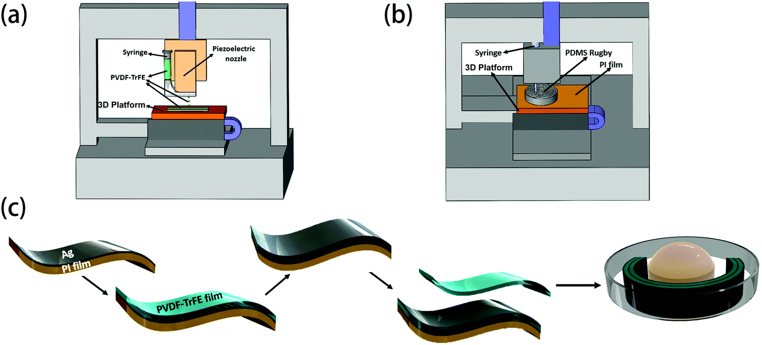 | ||
| Fig. 6 (a) A schematic diagram of the 3D-printing process for multilayer PVDF-TrFE/Ag films. (b) A schematic diagram of the 3D printing process for the PDMS rugby ball. (c) A schematic diagram of the preparation process for the rugby ball PEH. | ||
| Ink | Viscosity (cP) | Pressure (Psi) | Substrate temperature (°C) |
|---|---|---|---|
| PVDF-TrFE | 50 | 5 | 45 |
| Ag | 250 | 10 | 35 |
| PDMS | 2000 | 25 | 60 |
The prepared multilayer for energy harvester application comprised six 10 μm layers of the PVDF-TrFE composite to give overall dimensions of 63 mm in length, 3 mm in width, and 60 μm in thickness, as shown in Fig. 1a. Its crystallization, dielectric and piezoelectric performances are characterized in Fig. 3. The prepared PDMS rugby ball had an equatorial radius (x-axis) of 5 mm, a polar radius (z-axis) of 1 mm and a height of 3 mm. The multilayer PVDF-TrFE film was wrapped around the long axis of the prepared PDMS rugby ball. Finally, a solid shell (made of rigid polymer) was used to hold the rugby ball harvester. Fig. 1d shows a photograph of the prepared RPEH. During measurements, the base of the PDMS rugby ball was fixed, and its top surface was subjected to a dynamic compression force FN. The positive and negative electrodes of the multilayer PVDF-TrFE film were wired to an oscilloscope for output voltage monitoring.
5.3 Characterizations of the PVDF-TrFE film and PVDF-TrFE PEH
The crystalline phase of the PVDF-TrFE film was characterized by X-ray diffraction (X’Pert3 Powder, PANalytical X-ray diffractometer). The cross section of the prepared multilayer film was observed using scanning electron microscopy (SEM, S-4800, Hitachi, Tokyo, Japan). The electromechanical performance was tested using a quasi-static piezoelectric meter (ZJ-3D, Institute of Acoustics, Beijing, China). The capacitance and impedance were characterized using an impedance analyzer (HP 4294A, Agilent Technology, USA).A digital force gauge was used to measure the dynamic pressing force FN applied to the PVDF-TrFE PEH (Aipu Metrology Instrument Co., Ltd, Zhejiang, China). The output voltages of the PEHs were measured with a digital storage oscilloscope (DSO6014A, Agilent Technologies). The output power of the PVDF-TrFE PEH was obtained by measuring the output voltage across load resistances ranging from 991 Ω to 3 MΩ.
Conflicts of interest
There are no conflicts to declare.Acknowledgements
This work was supported by the National Natural Science Foundation of China (Grant No. 51772005 and 51072003) and the Beijing Key Laboratory for Magnetoelectric Materials and Devices.References
- K. Parida, V. Kumar, W. Jiangxin, V. Bhavanasi, R. Bendi and P. S. Lee, Adv. Mater., 2017, 29, 1702181 CrossRef PubMed.
- R. Liu, X. Kuang, J. Deng, Y. Wang, A. C. Wang, W. Ding, Y. Lai, J. Chen, P. Wang, Z. Lin, H. J. Qi, B. Sun and Z. L. Wang, Adv. Mater., 2018, 30, 1705195 CrossRef PubMed.
- M. Haras and T. Skotnicki, Nano Energy, 2018, 54, 461 CrossRef CAS.
- C. Gao, Y. Yin, L. Zheng, Y. Liu, S. Sim, Y. He, C. Zhu, Z. Liu, H. Lee, Q. Yuan and S. W. Lee, Adv. Funct. Mater., 2018, 28, 1803129 CrossRef.
- M. G. Kang, R. Sriramdas, H. Lee, J. Chun, D. Maurya, G. T. Hwang, J. Ryu and S. Priya, Adv. Energy Mater., 2018, 8, 1703313 CrossRef.
- X. Pu, M. M. Liu, X. Y. Chen, J. M. Sun, C. H. Du, Y. Zhang, J. Y. Zhai, W. G. Hu and Z. L. Wang, Sci. Adv., 2017, 3, e1700015 CrossRef.
- F. R. Fan, W. Tang and Z. L. Wang, Adv. Mater., 2016, 28, 4283 CrossRef CAS PubMed.
- A. S. M. Zahid Kausar, A. W. Reza, M. U. Saleh and H. Ramiah, Renewable Sustainable Energy Rev., 2014, 38, 973 CrossRef.
- Y. Bai, H. Jantunen and J. Juuti, Adv. Mater., 2018, 30, 1707271 CrossRef PubMed.
- F. R. Fan, W. Tang and Z. L. Wang, Adv. Mater., 2016, 28, 4283 CrossRef CAS PubMed.
- N. Ma, K. Zhang and Y. Yang, Adv. Mater., 2017, 29, 1703694 CrossRef.
- K. Zhang, S. Wang and Y. Yang, Adv. Energy Mater., 2017, 7, 1601852 CrossRef.
- J. Lustikova, Y. Shiomi, N. Yokoi, N. Kabeya, N. Kimura, K. Ienaga, S. Kaneko, S. Okuma, S. Takahashi and E. Saitoh, Nat. Commun., 2018, 9, 1–6 CrossRef PubMed.
- K. Zhang, S. Wang and Y. Yang, Adv. Energy Mater., 2017, 7, 1601852 CrossRef.
- R. J. M. Vullers, R. van Schaijk, I. Doms, C. Van Hoof and R. Mertens, Solid-State Electron., 2009, 53, 684 CrossRef CAS.
- M. Marzencki, Y. Ammar and S. Basrour, Sens. Actuators, A, 2008, 363, 145–146 Search PubMed.
- H. Kawai, Jpn. J. Appl. Phys., 1969, 8, 975 CrossRef CAS.
- R. Gregorio, J. Appl. Polym. Sci., 2006, 100, 3272 CrossRef CAS.
- B. B. Tian, X. F. Bai, Y. Liu, P. Gemeiner, X. L. Zhao, B. L. Liu, Y. H. Zou, X. D. Wang, H. Huang, J. L. Wang, S. Sun, J. L. Sun, B. Dkhil, X. J. Meng and J. H. Chu, Appl. Phys. Lett., 2015, 106, 92902 CrossRef.
- V. Cauda, S. Stassi, K. Bejtka and G. Canavese, ACS Appl. Mater. Interfaces, 2013, 5, 6430 CrossRef CAS.
- S. Bae, O. Kahya, B. K. Sharma, J. Kwon, H. J. Cho, B. Özyilmaz and J. Ahn, ACS Nano, 2013, 7, 3130 CrossRef CAS PubMed.
- K. K. Shung, J. M. Cannata and Q. F. Zhou, J. Electroceram., 2007, 19, 141 CrossRef.
- D. Vatansever, R. L. Hadimani, T. Shah and E. Siores, Smart Mater. Struct., 2011, 20, 55019 CrossRef.
- W. Wang, X. He, X. Wang, M. Wang and K. Xue, Sens. Actuators, A, 2018, 279, 467 CrossRef CAS.
- S. Cha, S. M. Kim, H. Kim, J. Ku, J. I. Sohn, Y. J. Park, B. G. Song, M. H. Jung, E. K. Lee, B. L. Choi, J. J. Park, Z. L. Wang, J. M. Kim and K. Kim, Nano Lett., 2011, 11, 5142 CrossRef CAS PubMed.
- D. Maurya, P. Kumar, S. Khaleghian, R. Sriramdas, M. G. Kang, R. A. Kishore, V. Kumar, H. Song, J. J. Park, S. Taheri and S. Priya, Appl. Energy, 2018, 232, 312 CrossRef.
- M. H. Chung, S. Yoo, H. J. Kim, J. Yoo, S. Y. Han, K. H. Yoo and H. Jeong, Sci. Rep., 2019, 5, 6581 CrossRef PubMed.
- H. Y. Lee and B. Choi, Smart Mater. Struct., 2013, 22, 115025 CrossRef.
- V. Bhavanasi, V. Kumar, K. Parida, J. Wang and P. S. Lee, ACS Appl. Mater. Interfaces, 2016, 8, 521 CrossRef CAS.
- W. Jung, M. Lee, M. Kang, H. G. Moon, S. Yoon, S. Baek and C. Kang, Nano Energy, 2015, 13, 174 CrossRef CAS.
- L. Dong, X. Han, Z. Xu, A. B. Closson, Y. Liu, C. Wen, X. Liu, G. P. Escobar, M. Oglesby, M. Feldman, Z. Chen and J. X. J. Zhang, Adv. Mater. Technol., 2018, 1800148 Search PubMed.
- L. M. Swallow, J. K. Luo, E. Siores, I. Patel and D. Dodds, Smart Mater. Struct., 2008, 17, 25017 CrossRef.
- S. You, H. Shi, J. Wu, L. Shan, S. Guo and S. Dong, J. Appl. Phys., 2016, 120, 234103 CrossRef.
- J. Ryu, J. Kim, J. Oh, S. Lim, J. Y. Sim, J. S. Jeon, K. No, S. Park and S. Hong, Nano Energy, 2019, 55, 348 CrossRef CAS.
- D. Kim, S. Hong, D. Li, H. S. Roh, G. Ahn, J. Kim, M. Park, J. Hong, T. Sung and K. No, RSC Adv., 2013, 3, 3194 RSC.
- D. Kim, H. S. Roh, Y. Kim, K. No and S. Hong, RSC Adv., 2015, 5, 10662 RSC.
- C. Wu, A. C. Wang, W. Ding, H. Guo and Z. L. Wang, Adv. Energy Mater., 2019, 9, 1802906 CrossRef.
- H. Askari, E. Hashemi, A. Khajepour, M. B. Khameseea and Z. L. Wang, Nano Energy, 2018, 53, 1003 CrossRef CAS.
- H. Askari, A. Khajepour, M. B. Khamesee, Z. Saadatnia and Z. L. Wang, Nano Today, 2018, 22, 10 CrossRef CAS.
- M. Xu, P. Wang, Y. Wang, S. L. Zhang, A. C. Wang, C. Zhang, Z. Wang, X. Pan and Z. L. Wang, Adv. Energy Mater., 2018, 8, 1702432 CrossRef.
- T. Cheng, Y. Li, Y. Wang, Q. Gao, T. Ma and Z. L. Wang, Nano Energy, 2019, 60, 137 CrossRef CAS.
- Z. L. Wang, Faraday Discuss., 2015, 176, 447 RSC.
- X. Li, M. Guo and S. Dong, IEEE Trans. Ultrason. Ferroelectr. Freq. Control, 2011, 58, 698 Search PubMed.
- X. Gao, J. Wu, Y. Yu, Z. Chu, H. Shi and S. Dong, Adv. Funct. Mater., 2018, 28, 1706895 CrossRef.
- X. Chen, J. Shao, X. Li and H. Tian, IEEE Trans. Nanotechnol., 2016, 15, 295 CAS.
- D. Tian, Y. Song and J. Lei, Chem. Soc. Rev., 2013, 42, 5184 RSC.
- W. Jung, M. Lee, S. Baek, I. K. Jung, S. Yoon and C. Kang, Nano Energy, 2016, 22, 514 CrossRef CAS.
- I. Jung, Y. Shin, S. Kim, J. Choi and C. Kang, Appl. Energy, 2017, 197, 222 CrossRef CAS.
- V. Bhavanasi, D. Y. Kusuma and P. S. Lee, Adv. Energy Mater., 2014, 4, 1400723 CrossRef.
- V. Jella, S. Ippili, J. Eom, J. Choi and S. Yoon, Nano Energy, 2018, 53, 46 CrossRef CAS.
- H. H. Singh and N. Khare, Nano Energy, 2018, 51, 216 CrossRef CAS.
- J. Fu, Y. Hou, X. Gao, M. Zheng and M. Zhu, Nano Energy, 2018, 52, 391 CrossRef CAS.
- F. Mokhtari, J. Foroughi, T. Zheng, Z. Cheng and G. M. Spinks, J. Mater. Chem. A, 2019, 78245 Search PubMed.
- X. T. S. C. Wei Zeng and A. S. H. Choy, Energy Environ. Sci., 2013, 6, 2631 RSC.
- K. Lim, J. Hupp and N. Lewis, Energy Environ. Sci., 2019, 12, 15 RSC.
- T. Park, B. Kim, Y. Kim and E. Kim, J. Mater. Chem. A, 2014, 2, 5462 RSC.
- S. Ye, C. Cheng, X. Chen, X. Chen, J. Shao, J. Zhang, H. Hu, H. Tian, X. Li, L. Ma and W. Jia, Nano Energy, 2019, 60, 701 CrossRef CAS.
- R. Ding, X. Zhang, G. Chen, H. Wang, R. Kishor, J. Xiao, F. Gao, K. Zeng, X. Chen, X. W. Sun and Y. Zheng, Nano Energy, 2017, 37, 126 CrossRef CAS.
- F. Mokhtari, J. Foroughi, T. Zheng, Z. Cheng and G. M. Spinks, J. Mater. Chem. A, 2019, 7, 8245 RSC.
- Y. Guo, X. Zhang, Y. Wang, W. Gong, Q. Zhang, H. Wang and J. Brugger, Nano Energy, 2018, 48, 152 CrossRef CAS.
- T. Huang, C. Wang, H. Yu, H. Wang, Q. Zhang and M. Zhu, Nano Energy, 2015, 14, 226 CrossRef CAS.
- Y. Fuh, P. Chen, Z. Huang and H. Ho, Nano Energy, 2015, 11, 671 CrossRef CAS.
- W. Jung, M. Kang, H. G. Moon, S. Baek, S. Yoon, Z. Wang, S. Kim and C. Kang, Sci. Rep., 2015, 5, 9309 CrossRef CAS.
- C. Lang, J. Fang, H. Shao, H. Wang, G. Yan, X. Ding and T. Lin, Nano Energy, 2017, 35, 146 CrossRef CAS.
- J. Granstrom, J. Feenstra, H. A. Sodano and K. Farinholt, Smart Mater. Struct., 2007, 16, 1810 CrossRef CAS.
Footnote |
| † Electronic supplementary information (ESI) available. See DOI: 10.1039/c9ee01785b |
| This journal is © The Royal Society of Chemistry 2020 |