 Open Access Article
Amidinate based indium(III) monohalides and β-diketiminate stabilized In(II)–In(II) bond: synthesis, crystal structure, and computational study†
Samya
Banerjee
 a,
Sayan
Dutta
 b,
Samir Kumar
Sarkar
 a,
Nico
Graw
 a,
Regine
Herbst-Irmer
 a,
Debasis
Koley
 *b,
Dietmar
Stalke
 *a and
Herbert W.
Roesky
 *a
*a
aInstitut für Anorganische Chemie, Georg-August-Universität Göttingen, 37077 Göttingen, Germany. E-mail: hroesky@gwdg.de; dstalke@chemie.uni-goettingen.de
bDepartment of Chemical Sciences, Indian Institute of Science Education and Research (IISER) Kolkata, Mohanpur 741 246, India. E-mail: koley@iiserkol.ac.in
First published on 1st October 2020
Abstract
Synthesis and bonding aspects of mononuclear bis-amidinate indium(III) monohalides L2InX (1–3), where L = PhC(NtBu)2; X is F (1), Br (2) or I (3) and β-diketiminate (NacNac) stabilized In(II) dimer (MesNacNac)2In2Br2 (4) with In–In bond are reported along with the single-crystal X-ray structures of 2–4.
Introduction
In recent years, amidinates, the NCN-analogues of the allylic group have attracted attention as ligands for main group elements.1–4 The importance of the amidinate/s supported compounds of group 13 elements are now well-established as catalysts for a number of catalytic transformations.5 Among the group 13 elements, amidinate complexes of aluminium are widely explored with various catalytic activities.5–9 Significant examples include CO2 fixation by aluminium amidinates catalysts,6,7 polymerization of ethylene by cationic amidinate aluminium alkyl complexes8 and ring-opening polymerization of rac-lactide by amidinate aluminium dialkyl complexes.9 Amidinate coordinated gallium complexes are well studied.10–13 For example, Dagorne et al. have reported neutral and cationic gallium amidinate complexes viz. {tBuC(NR)2}GaX2 where X = Cl, Me, Et, CH2Ph and R = iPr, Cy, tBu and {MeC(NiPr)2}2Ga2Me3+, respectively.10,11 Lappert and others reported Ga(L)Cl2 with L = N(SiMe3)C(Ph)N(CH2)3NMe2.12Although, amidinate complexes of aluminium and gallium are well studied,5–13 indium amidinate conjugates are rare in the literature. Zhou and Richeson synthesized indium(III) amidinate complexes, In[CyNC(Me)NCy]2Cl, In[CyNC(Me)NCy]3 and In[CyNC(CMe3)NCy]2Cl.14,15 The η3-coordination mode of amidinate to an In(I) centre is reported by Jones and co-workers.16 They also developed amidinate coordinated indium(III) monohydride.17 In 2017, Gebhard et al. have reported indium(III) complexes of the formulation [InCl(amd)2], [InMe(amd)2] and [In(amd)3] with amd = (iPrN)2CMe.18 Thus, although amidinate In(III) monohydride and monochloride is reported, amidinate based In(III) monohalide with fluoride, bromide and iodide are not explored yet. It is important to mention that these amidinate based In(III) monohalide might have exciting catalytic activity as the well-defined In(III) species are catching attention due to their distinct catalytic reactivity.19,20 Significant examples include ring-opening polymerization by the cationic and neutral In(III) compounds respectively as recently reported by Mehrkhodavandi et al.19,20
The indium–indium (In–In) single bond is reported in the literature with various indium coordinating ligands.21–24 For example, Schluter et al. used 2,4,6-tris(trifluoromethyl)phenyl as a ligand to stabilize In(II)–In(II) bond.21 Godfrey and co-workers reported In–In bond in the phosphine based In(II) complex viz. In2I4(PnPr3)2.22 Recently, a cyclic tetraindium cluster with In–In bonds are reported by Protchenko and others.23 In spite of several reports of compounds with In–In bonds, β-diketiminate (NacNac) stabilized In–In single bond is rare in the literature although NacNac is widely used to stabilize compounds of low valent elements.25
These two above discussed unexplored synthetic challenges provided us with the background of this work. Herein, we have synthesized and characterized bis(amidinate)indium(III) monohalides (1–3) with F, Br, and I as the halide and NacNac stabilized In(II) dimer with In–In bond (4). 2–4 are characterized by crystal X-ray crystallography. The structure and Bonding aspects of 1–4 are probed by computational calculations.
Results and discussion
Synthetic procedures
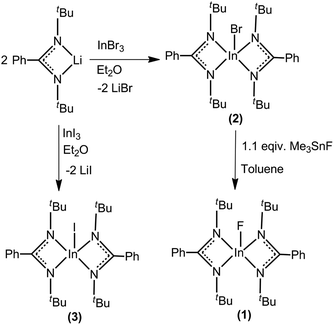
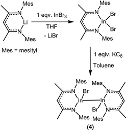
The complexes 2 and 3 were synthesized by treating one equivalent of InX3 (X = Br/I) with two equivalents of [PhC(NtBu)2]Li in Et2O under nitrogen atmosphere (Scheme 1). Complex 1 was synthesized from complex 2 by treatment with one equivalent of trimethyl tin fluoride in toluene under nitrogen atmosphere. All these three compounds were isolated as colorless solids. In the case of the bromide and iodide compounds (2 and 3), single crystals were grown from concentrated diethyl ether solutions at −30 °C in 3 days.Compound 4 was synthesized in two steps (Scheme 2). Metathesis reaction between the lithium β-diketiminate, (MesNacNac)Li where (MesNacNac)Li is [CH{(Me)CN-(2,4,6-Me3C6H2)}2Li], and InBr3 in THF gives (MesNacNac)InBr2. Reduction of (MesNacNac)InBr2 with one equivalent of KC8 in toluene at room temperature for 2 days gives a colorless solution of (MesNacNac)2In2Br2 (4). Colorless crystals of 4 were isolated from the concentrated solution in toluene at −30 °C. Compound 4 is stable for months under an inert atmosphere in toluene at room temperature, and also in the solid-state at room temperature.
The compounds (1–4) were well characterized by X-ray crystallography, 1H and 13C NMR and elemental analysis.
Crystallography
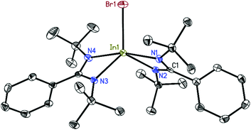
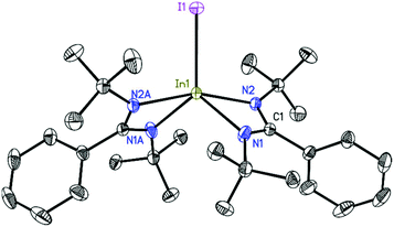
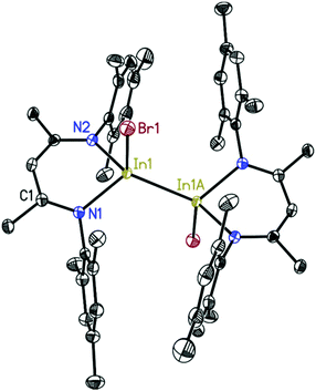
The structures of 2, 3, and 4 were determined by single-crystal X-ray diffraction.26–31 Compound 2 (Fig. 1) crystallizes in the monoclinic space group P21/c with one molecule in the asymmetric unit. The indium atom is roughly linearly coordinated (164.53(6)°) by the two nitrogen atoms N1 and N4 resulting in an overall coordination environment best described as distorted trigonal–bipyramidal, also indicated by the Addison parameter32τ = 0.84 (τ = 1 for ideal trigonal–bipyramidal geometry). Furthermore, from toluene solution, 2 crystallizes in the monoclinic space group P21/n with a larger unit cell additionally containing half a molecule of toluene as lattice solvent (see ESI†). Compound 3 (Fig. 2) crystallizes in the monoclinic space group C2/c with half a molecule in the asymmetric unit. The bigger iodine atom decreases the N2–In1–N2A bond angle (160.87(5)°) resulting in a slightly higher deviation from linearity compared to compound 2. Still, the overall geometry can be described as a distorted trigonal bipyramid.Compound 4 (Fig. 3) crystallizes in the monoclinic space group P21/c with half of the molecule in the asymmetric unit. In1 is dislocated from the C3N2 ligand plane by 0.6664(18) Å (rms 0.0423 Å). The coordination of In1 can be described as a distorted tetrahedral. A database search33 shows the In–In bond distance of 4 (2.7100(5) Å) to be within the range of reported values (2.6460–2.9380 Å) for In–In singly bonded structures with three- or four-fold coordinated indium atoms (only structures with In bonded to non-metals were included in the search). Compared to other NacNac stabilized In(II) halide dimers the In–In bond distances in 4 is shorter than in [{HC(CMeNAr)2}InCl]234 (2.8342(7) Å) and [{PhC(C(H)NAr)2}InCl]235 (2.7502(3)–2.8290(6) Å) (Ar = 2,6-i-Pr2C6H3) (the range in the latter case is due to different lattice solvents or their absence).
Theoretical calculations
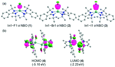
Quantum chemical calculations were performed at the R-BP86/def2-TZVP//R-BP86/def2-SVP level to cast light on the bonding scenario in the compounds (1–4) at singlet ground electronic states. The optimized geometrical parameters are in good agreement with the X-ray crystal structures as seen from the alignment and superposition of the geometries (Fig. S15, ESI†).For a better understanding of the bonding environment, the natural bond orbital (NBO) analyses were accomplished on the optimized geometries. The In–X bonds with occupancies of 1.807–1.946 e are significantly polarized toward the halogen atoms [F1: 94.7% (1); Br1: 86.3% (2); I1: 86.2% (3); Br1/Br1A: 85.5/85.5% (4)] (Table S7, ESI†). The shapes of the In–X σ NBOs in these compounds are depicted in Fig. 4a and Fig. S17, ESI.† The relatively greater polar nature of the In1–F1 bond in comparison with other In–X bonds is attributed to the remarkably high electronegativity of fluorine (4.10) compared to that of bromine (2.74) and iodine (2.21). Meanwhile, the In–X bonds in 1–3 are formed by the overlap of sp3d and sp3 hybrid orbitals of indium and halogen atoms, respectively. Importantly, the indium atoms utilize sp3 hybrid orbitals with marginal p-mixing for the formation of In1–Br1 and In1A–Br1A bonds in 4. The In–X bonds exhibit single bond character, as evidenced by the corresponding Wiberg bond indices (WBI) values (In1–F1: 0.332 (1); In1–Br1: 0.646 (2); In1–I1: 0.734 (3); In1–Br1/In1A–Br1A: 0.592/0.592 (4). The In–X bond polarizations are also in accordance with the NPA charges on the metal centers (In1: +1.849/+1.576/+1.492 e in 1/2/3). Additionally, the sp3 hybrid orbitals with slight s-mixing of both the indium atoms participate in the formation of the In1–In1A bond in 4 and the corresponding σ-bonded electron density is equally contributed by the bonding partners. The WBI value of 0.788 justifies the presence of a single bond between the indium centers. Inspection of the frontier molecular orbitals reveal that the HOMOs in 1–3 are representatives of lone pair orbitals located on the nitrogen atoms in the amidinate ligand, whereas that in 4 mainly represents the π orbital distributed on the core five-membered ring framework in the β-diketiminate ligand (Fig. 4b and Fig. S18, ESI†). Besides, the LUMOs in 1 and 2 possess the π* orbitals of the phenyl rings in the amidinate ligand. On the other hand, the LUMO in 3 shows the In1–I1 σ* orbital, while the In1–Br1 and In1A–Br1A σ* orbitals populate the LUMO in 4. Notwithstanding the similar energies of HOMOs in all the compounds, the appreciable stabilization of LUMO in 4 compared to that in 1–3 results in the substantially lower HOMO–LUMO energy gap (ΔEH−L) in the former one [ΔEH−L: 3.22–3.24 eV (1–3); 2.87 eV (4)].
Importantly, the optimized geometry of 2 shows significantly longer In1–N1/In1–N4 bond distances (2.316/2.310 Å) compared to the In1–N2/In1–N3 bonds (2.257/2.259 Å), as noticed in the crystal structure. The unequal indium–nitrogen bond lengths in 2 can be elucidated by the second-order perturbation theory analysis. Our calculations suggest that the delocalization of the In1–Br1 bonding electron pair to the formally empty In1–N1/In1–N4 σ* orbital stabilizes the compound 2, and the corresponding 2e stabilization energies are computed to be 38.9/36.8 kcal mol−1. Such stabilization owing to the interaction between the In1–Br1 σ orbital and the In1–N2/In1–N3 σ* orbital is substantially reduced to 3.9/3.4 kcal mol−1. Similar notable differences in the In–N bond lengths in 3 can also be explained with previous justification (Table S9, ESI†).
The NBO proposed electronic scenario was further investigated by QTAIM calculations. Interestingly, though the covalent In–X bonds show slightly higher electron densities at the (3, −1) bond critical points (BCPs) in the range of 0.051–0.090 e Å−3, the positive Laplacian [∇2ρ(r)] values at BCPs account for its highly polarized nature (Table S10, ESI†).36,37
Experimental
Materials and methods
All reactions and handling of reagents were performed using standard Schlenk and glovebox techniques under an atmosphere of high purity N2. Commercial reagents were purchased from Aldrich, Acros, or Alfa-Aesar Chemical Co. and used as received. Toluene, THF were distilled over Na/K alloy (25![[thin space (1/6-em)]](https://www.rsc.org/images/entities/char_2009.gif) :
:![[thin space (1/6-em)]](https://www.rsc.org/images/entities/char_2009.gif) 75) and diethyl ether was distilled over potassium mirror. C6D6 was dried by stirring for 2 days over Na/K alloy followed by distillation in a vacuum and degassed. 1H, 13C{1H} NMR spectra were recorded on Bruker Avance 400, and Bruker Avance 500 MHz NMR spectrometers and were referenced to the TMS. Elemental analysis was performed by the Analytisches Labor für Anorganische Chemie für Universität Göttingen.
75) and diethyl ether was distilled over potassium mirror. C6D6 was dried by stirring for 2 days over Na/K alloy followed by distillation in a vacuum and degassed. 1H, 13C{1H} NMR spectra were recorded on Bruker Avance 400, and Bruker Avance 500 MHz NMR spectrometers and were referenced to the TMS. Elemental analysis was performed by the Analytisches Labor für Anorganische Chemie für Universität Göttingen.
Synthesis
Elemental analysis (%) calcd for C30H46FInN4: C, 60.40; H, 7.77; N, 9.39; found: C, 61.16; H, 7.97; N, 9.23. 1H NMR (400 MHz, C6D6, 25 °C): δ 1.26 ppm (s, 36H, tBu), 6.93–7.00 ppm (m, 6H, Ph), 7.11–7.14 ppm (m, 4H, Ph). 13C{1H} NMR (125.7 MHz, C6D6, 25 °C): δ 33.2 (tBu), 53.7 (tBu), 127.4, 127.7, 128.0, 129.9, 137.3 (Ph), 170.4 ppm (NCN). 19F NMR (470 MHz, C6D6): δ = −78.32 ppm.
Elemental analysis (%) calcd for C30H46BrInN4 (656.19): C, 54.81; H, 7.05; N, 8.52; found: C, 54.56; H, 7.14; N, 8.46. 1H NMR (400 MHz, C6D6, 25 °C): δ 1.22 ppm (s, 36H, tBu), 6.90–6.99 ppm (m, 6H, Ph), 7.09–712 ppm (d, 4H, Ph). 13C{1H}NMR (125.75 MHz, C6D6, 25 °C): δ 32.9 (tBu), 52.7 (tBu), 126.9, 127.3, 127.7, 128.3, 137.0 (Ph), 170.8 ppm (NCN).
Elemental analysis (%) calcd for C30H46IInN4 (704.18): C, 51.15; H, 6.58; N, 7.95; found: C, 51.31; H, 6.76; N, 7.86. 1H NMR (400 MHz, C6D6, 25 °C): δ 0.95 ppm (s, 36H, tBu), 6.79–7.02 ppm (m, 10H, Ph). 13C{1H} NMR (125.7 MHz, C6D6, 25 °C): δ 31.6 (tBu), 52.5 (tBu), 127.3, 127.5, 127.7, 128.0, 129.5 (Ph), 179.3 ppm (NCN).
Elemental analysis (%) calcd for C46H58Br2In2N4 (1054.11): C, 52.30; H, 5.53; N, 5.30; found: C, 52.64; H, 5.65; N, 5.24. 1H NMR (400 MHz, C6D6, 25 °C): δ 1.39 (s, 12H; CCH3), 2.05 (s, 12H; p-CH3), 2.40 (s, 24H; o-CH3), 4.98 (s, 2H; CH), 6.73 ppm (s, 8H; Ar–H). 13C{1H} NMR (75.5 MHz, C6D6, 25 °C): δ 20.5 (o-CH3), 20.7 (p-CH3), 23.0 (CCH3), 99.5 (CH), 127.4 (Ar–C), 127.7 (Ar–C), 128.0 (Ar–C), 130.0, 133.4, 136.4, 138.3, 171.4 ppm (NCCH3).
Computational details
All computations reported in this article were performed employing DFT method implemented in the Gaussian 09 suite of programs.38 Geometry optimizations were carried out using gradient-corrected BP86 functional39,40 in conjunction with the Ahlrichs’ split valence plus polarization (def2-SVP) basis set41,42 for all the atoms along with the corresponding effective core potentials (ECPs) for indium and iodine atoms. BP86 is composed of Becke's 1988 exchange and Perdew's 1986 correlation functionals. No symmetry constraints were imposed during geometry optimizations. Frequency calculations were accomplished at the same level on the optimized geometries to characterize the nature of stationary points. All of the structures were verified as true minima on the potential energy surface in the absence of imaginary frequency. Single-point calculations were performed on optimized geometries using BP86 functional in combination with the def2-TZVP basis set41,42 for all the atoms along with the corresponding ECPs for indium and iodine atoms. Tight wave function convergence criteria and an “ultrafine” (99![[thin space (1/6-em)]](https://www.rsc.org/images/entities/char_2009.gif) 950) grid were used in numerical integration during single-point calculations. Natural bond orbital (NBO)43,44 analysis was performed at the R-BP86/def2-TZVP//R-BP86/def2-SVP level using the NBO Version 3.1 program. Wiberg bond indices (WBI) were calculated at the same level of theory.45
950) grid were used in numerical integration during single-point calculations. Natural bond orbital (NBO)43,44 analysis was performed at the R-BP86/def2-TZVP//R-BP86/def2-SVP level using the NBO Version 3.1 program. Wiberg bond indices (WBI) were calculated at the same level of theory.45
Furthermore, QTAIM (quantum theory of atoms in molecules) calculations were performed in the AIMALL Version 17.01.25 software package46 to characterize the electron distribution around selected bonds in the chemical species by applying Bader's AIM (atoms-in-molecules) theory.47 Importantly, any two bonded atoms are connected through a bond path where the electron density [ρ(r)] shows the maximum value. The bond critical point (BCP) is characterized by a point on the bond path where the gradient [∇ρ(r)] of the electron density is equal to zero. The magnitude of the electron density [ρ(r)] and its Laplacian [∇2ρ(r)] at the BCP convey important information about the strength and type of chemical bond. The Laplacian indicates whether the electron density is locally concentrated [∇2ρ(r) < 0] or depleted [∇2ρ(r) > 0]. The extent to which density is preferentially accumulated in a given plane containing the bond path is denoted by the term ellipticity (ε). Orbital diagrams were rendered in Chemcraft48 and optimized geometries were prepared using the CYLview49 visualization software.
Conclusions
In summary, we present a successful use of amidinate scaffold for the synthesis of bis(amidinate)indium(III) monohalides. X-ray crystal structures of the compounds 2 and 3 are the first examples of bis(amidinate)indium(III) monobromide and monoiodide whereas compound 1 is the first example of bis(amidinate)indium(III) monofluoride. We are also able to stabilize In(II) dimer viz. (MesNacNac)2In2Br2 (4) with In–In bond. This indicates the ability of β-diketiminate ligand for stabilizing In(II)–In(II) bond. Overall, the combined experimental and theoretical studies indicate the utility of amidinate and β-diketiminate ligands for the development of interesting novel indium compounds which might have potential applications in catalysis.Conflicts of interest
There are no conflicts to declare.Acknowledgements
H. W. R. thanks the DFG for financial support (RO 224/71-1). D.St. thanks the Danish National Research Foundation (DNRF93) funded Center for Materials Crystallography (CMC). S. D. acknowledges the CSIR, India, for the Senior Research Fellowship (SRF) and IISER Kolkata for the computational facility. D. K. acknowledges the funding from bilateral DST-DFG (INT/FRG/DFG/P-05/2017) scheme.Notes and references
- S. S. Sen, H. W. Roesky, D. Stern, J. Henn and D. Stalke, J. Am. Chem. Soc., 2010, 132, 1123–1126 CrossRef CAS.
- S. Khoo, Y.-L. Shan, M.-C. Yang, Y. Li, M.-D. Su and C.-W. So, Inorg. Chem., 2018, 57, 5879–5887 CrossRef CAS.
- C. N. de Bruin-Dickason, T. Sutcliffe, C. A. Lamsfus, G. B. Deacon, L. Maron and C. Jones, Chem. Commun., 2018, 54, 786–789 RSC.
- T. Chlupatý, M. Bílek, J. Merna, J. Brus, Z. Růžičková, T. Strassner and A. Růžička, Dalton Trans., 2019, 48, 5335–5342 RSC.
- S. Dagorne and R. Wehmschulte, ChemCatChem, 2018, 10, 2509–2520 CrossRef CAS.
- D. O. Meléndez, A. Lara-Sánchez, J. Martínez, X. Wu, A. Otero, J. A. Castro-Osma, M. North and R. S. Rojas, ChemCatChem, 2018, 10, 2271–2277 CrossRef.
- Y. R. Yepes, C. Quintero, D. O. Meléndez, C. G. Daniliuc, J. Martínez and R. S. Rojas, Organometallics, 2019, 38, 469–478 CrossRef.
- M. P. Coles and R. F. Jordan, J. Am. Chem. Soc., 1997, 119, 8125–8126 CrossRef CAS.
- F. Qian, K. Liu and H. Ma, Dalton Trans., 2010, 39, 8071–8083 RSC.
- S. Dagorne, I. A. Guzei, M. P. Coles and R. F. Jordan, J. Am. Chem. Soc., 2000, 122, 274–289 CrossRef CAS.
- S. Dagorne, R. F. Jordan and V. G. Young, Organometallics, 1999, 18, 4619–4623 CrossRef CAS.
- D. Doyle, Y. K. Gun'ko, P. B. Hitchcock and M. F. Lappert, Dalton Trans., 2000, 4093–4097 RSC.
- A. P. Kenney, G. P. A. Yap, D. S. Richeson and S. T. Barry, Inorg. Chem., 2005, 44, 2926–2933 CrossRef CAS.
- L. A. Lesikar and A. F. Richards, Polyhedron, 2010, 29, 1411–1422 CrossRef CAS.
- Y. Zhou and D. S. Richeson, Inorg. Chem., 1996, 35, 2448–2451 CrossRef CAS.
- C. Jones, P. C. Junk, J. A. Platts, D. Rathmann and A. Stasch, Dalton Trans., 2005, 2497–2499 RSC.
- R. J. Baker, C. Jones, P. C. Junk and M. Kloth, Angew. Chem., Int. Ed., 2004, 43, 3852–3855 CrossRef CAS.
- M. Gebhard, M. Hellwig, A. Kroll, D. Rogalla, M. Winter, B. Mallick, A. Ludwig, M. Wiesing, A. D. Wieck, G. Grundmeier and A. Devi, Dalton Trans., 2017, 46, 10220–10231 RSC.
- C. Goonesinghe, H. Roshandel, C. Diaz, H.–J. Jung, K. Nyamayaro, M. Ezhova and P. Mehrkhodavandi, Chem. Sci., 2020, 11, 6485–6491 RSC.
- D. C. Aluthge, J. M. Ahn and P. Mehrkhodavandi, Chem. Sci., 2015, 6, 5284–5292 RSC.
- R. D. Schluter, A. H. Cowley, D. A. Atwood, R. A. Jones, M. R. Bond and C. J. Carrano, J. Am. Chem. Soc., 1993, 115, 2070–2071 CrossRef CAS.
- S. M. Godfrey, K. J. Kelly, P. Kramkowski, C. A. McAuliffe and R. G. Pritchard, Chem. Commun., 1997, 1001–1002 RSC.
- A. V. Protchenko, J. Urbano, J. A. B. Abdalla, J. Campos, D. Vidovic, A. D. Schwarz, M. P. Blake, P. Mountford, C. Jones and S. Aldridge, Angew. Chem., Int. Ed., 2017, 56, 15098–15102 CrossRef CAS.
- V. Lomeli, B. G. McBurnett and A. H. Cowley, J. Organomet. Chem., 1998, 562, 123–125 CrossRef CAS.
- Z. Mingdong, S. Sinhababu and H. W. Roesky, Dalton Trans., 2020, 49, 1351–1364 RSC.
- The data were integrated with SAINT.27 A multi-scan absorption correction was applied using SADABS.28 The structures were solved by SHELXT29 and refined on F2 using SHELXL30 in the graphical user interface SHELXLE.31 Crystal data for 2 at 100(2) K: C30H46BrInN4, Mr = 657.44 g mol−1, 0.173 × 0.149 × 0.094 mm, monoclinic, P21/c, a = 10.025(2) Å, b = 11.767(2) Å, c = 26.548(3) Å, β = 99.56(2), V = 3088.2(9) Å3, Z = 4, μ(Ag Kα) = 1.116 mm−1, θmax = 20.545°, 58
![[thin space (1/6-em)]](https://www.rsc.org/images/entities/char_2009.gif) 248 reflections measured, 6337 independent (Rint = 0.0662), R1 = 0.0257 [I > 2σ(I)], wR2 = 0.0517 (all data), res. density peaks: 0.393 to −0.355 e Å3, CCDC 2027411.† Crystal data for 2a at 100(2) K: C30H46BrInN4·0.5 C7H8, Mr = 703.50 g mol−1, 0.374 × 0.239 × 0.128 mm, monoclinic, P21/n, a = 9.763(2) Å, b = 21.991(3) Å, c = 15.761(2) Å, β = 94.32(2), V = 3374.2(9) Å3, Z = 4, μ(Mo Kα) = 1.912 mm−1, θmax = 27.497°, 74
248 reflections measured, 6337 independent (Rint = 0.0662), R1 = 0.0257 [I > 2σ(I)], wR2 = 0.0517 (all data), res. density peaks: 0.393 to −0.355 e Å3, CCDC 2027411.† Crystal data for 2a at 100(2) K: C30H46BrInN4·0.5 C7H8, Mr = 703.50 g mol−1, 0.374 × 0.239 × 0.128 mm, monoclinic, P21/n, a = 9.763(2) Å, b = 21.991(3) Å, c = 15.761(2) Å, β = 94.32(2), V = 3374.2(9) Å3, Z = 4, μ(Mo Kα) = 1.912 mm−1, θmax = 27.497°, 74![[thin space (1/6-em)]](https://www.rsc.org/images/entities/char_2009.gif) 445 reflections measured, 7762 independent (Rint = 0.0308), R1 = 0.0172 [I > 2σ(I)], wR2 = 0.0415 (all data), res. density peaks: 0.372 to −0.191 e Å3, CCDC 2027412.† Crystal data for 3 at 100(2) K: C30H46IInN4, Mr = 704.43 g mol−1, 0.347 × 0.228 × 0.170 mm, monoclinic, C2/c, a = 20.114(3) Å, b = 9.710(2) Å, c = 16.382(2) Å, β = 94.76(2), V, = 3188.5(9) Å3, Z = 4, μ(Mo Kα) = 1.733 mm−1, θmax = 28.334°, 54
445 reflections measured, 7762 independent (Rint = 0.0308), R1 = 0.0172 [I > 2σ(I)], wR2 = 0.0415 (all data), res. density peaks: 0.372 to −0.191 e Å3, CCDC 2027412.† Crystal data for 3 at 100(2) K: C30H46IInN4, Mr = 704.43 g mol−1, 0.347 × 0.228 × 0.170 mm, monoclinic, C2/c, a = 20.114(3) Å, b = 9.710(2) Å, c = 16.382(2) Å, β = 94.76(2), V, = 3188.5(9) Å3, Z = 4, μ(Mo Kα) = 1.733 mm−1, θmax = 28.334°, 54![[thin space (1/6-em)]](https://www.rsc.org/images/entities/char_2009.gif) 423 reflections measured, 3971 independent (Rint = 0.0240), R1 = 0.0146 [I > 2σ(I)], wR2 = 0.0369 (all data), res. density peaks: 0.751 to −0.766 e Å−3, CCDC 2027413.† Crystal data for 4 at 100(2) K: C46H85Br2In2N4, Mr = 1056.42 g mol−1, 0.576 × 0.303 × 0.246 mm, monoclinic, P21/c, a = 12.090(2) Å, b = 10.962(2) Å, c = 17.663(2) Å, β = 104.50(2), V, = 2245.7(7) Å3, Z = 2, μ(Mo Kα) = 2.841 mm−1, θmax = 27.502°, 24
423 reflections measured, 3971 independent (Rint = 0.0240), R1 = 0.0146 [I > 2σ(I)], wR2 = 0.0369 (all data), res. density peaks: 0.751 to −0.766 e Å−3, CCDC 2027413.† Crystal data for 4 at 100(2) K: C46H85Br2In2N4, Mr = 1056.42 g mol−1, 0.576 × 0.303 × 0.246 mm, monoclinic, P21/c, a = 12.090(2) Å, b = 10.962(2) Å, c = 17.663(2) Å, β = 104.50(2), V, = 2245.7(7) Å3, Z = 2, μ(Mo Kα) = 2.841 mm−1, θmax = 27.502°, 24![[thin space (1/6-em)]](https://www.rsc.org/images/entities/char_2009.gif) 146 reflections measured, 5144 independent (Rint = 0.0243), R1 = 0.0173 [I > 2σ(I)], wR2 = 0.0454 (all data), res. density peaks: 0.448 to −0.280 e Å−3, CCDC: 2027414.†.
146 reflections measured, 5144 independent (Rint = 0.0243), R1 = 0.0173 [I > 2σ(I)], wR2 = 0.0454 (all data), res. density peaks: 0.448 to −0.280 e Å−3, CCDC: 2027414.†. - Bruker AXS Inc. in Bruker Apex CCD,SAINT v8.38C, ed. Bruker AXS Inst. Inc. WI, USA, Madison, 2017.
- L. Krause, R. Herbst-Irmer, G. M. Sheldrick and D. Stalke, J. Appl. Crystallogr., 2015, 48, 3–10 CrossRef CAS.
- G. M. Sheldrick, Acta Crystallogr., 2015, A71, 3–8 CrossRef.
- G. M. Sheldrick, Acta Crystallogr., 2015, C71, 3–8 CrossRef.
- C. B. Hübschle, G. M. Sheldrick and B. Dittrich, J. Appl. Crystallogr., 2011, 44, 1281–1284 CrossRef.
- A. W. Addison, T. N. Rao, J. Reedijk, J. V. Rijn and G. C. Verschoor, J. Chem. Soc., Dalton Trans., 1984, 1349–1356 RSC.
- I. J. Bruno, J. C. Cole, P. R. Edgington, M. Kessler, C. F. Macrae, P. McCabe, J. Pearson and R. Taylor, Acta Cryst., 2002, B58, 389–397 CAS.
- M. Stender and P. P. Power, Polyhedron, 2002, 21, 525–529 CrossRef CAS.
- Y. Cheng, D. J. Doyle, P. B. Hitchcock and M. F. Lappert, Dalton Trans., 2006, 4449–4460 RSC.
- T. Mondal, S. Dutta, S. De, D. Thirumalai and D. Koley, J. Phys. Chem. A, 2019, 123, 565–581 CrossRef CAS.
- S. Kundu, S. Sinhababu, S. Dutta, T. Mondal, D. Koley, B. Dittrich, B. Schwederski, W. Kaim, A. C. Stückl and H. W. Roesky, Chem. Commun., 2017, 53, 10516–10519 RSC.
- M. J. Frisch, G. W. Trucks, H. B. Schlegel, G. E. Scuseria, M. A. Robb, J. R. Cheeseman, G. Scalmani, V. Barone, B. Mennucci, G. A. Petersson, G. H. Nakatsuji, M. Caricato, X. Li, H. P. Hratchian, A. F. Izmaylov, J. Bloino, G. Zheng, J. L. Sonnenberg, M. Hada, M. Ehara, K. Toyota, R. Fukuda, J. Hasegawa, M. Ishida, T. Nakajima, Y. Honda, O. Kitao, H. Nakai, T. Vreven, J. A. Montgomery Jr., J. E. Peralta, F. Ogliaro, M. Bearpark, J. J. Heyd, E. Brothers, K. N. Kudin, V. N. Staroverov, R. Kobayashi, J. Normand, K. Raghavachari, A. Rendell, J. C. Burant, S. S. Iyengar, J. Tomasi, M. Cossi, N. Rega, J. M. Millam, M. Klene, J. E. Knox, J. B. Cross, V. Bakken, C. Adamo, J. Jaramillo, R. Gomperts, R. E. Stratmann, O. Yazyev, A. J. Austin, R. Cammi, C. Pomelli, J. W. Ochterski, R. L. Martin, K. Morokuma, V. G. Zakrzewski, G. A. Voth, P. Salvador, J. J. Dannenberg, S. Dapprich, A. D. Daniels, O. Farkas, J. B. Foresman, J. V. Ortiz, J. Cioslowski and D. J. Fox, Gaussian 09, Revision D.01, Gaussian, Inc., Wallingford, CT, 2013 Search PubMed.
- A. D. Becke, Phys. Rev. A: At., Mol., Opt. Phys., 1988, 38, 3098–3100 CrossRef CAS.
- J. P. Perdew, Phys. Rev. B: Condens. Matter Mater. Phys., 1986, 33, 8822–8824 CrossRef.
- D. Andrae, U. Häußermann, M. Dolg, H. Stoll and H. Preuß, Theor. Chim. Acta, 1990, 77, 123–141 CrossRef CAS.
- B. Metz, H. Stoll and M. J. Dolg, Chem. Phys., 2000, 113, 2563–2569 CAS.
- E. D. Glendening, A. E. Reed, J. E. Carpenter and F. Weinhold, NBO, Version 3.1, Gaussian, Inc., Wallingford, CT, 2009 Search PubMed.
- A. E. Reed, L. A. Curtiss and F. Weinhold, Chem. Rev., 1988, 88, 899–926 CrossRef CAS.
- K. B. Wiberg, Tetrahedron, 1968, 24, 1083–1096 CrossRef CAS.
- T. A. Keith, AIMAll (Version 17.01.25), TK Gristmill Software, Overland Park KS, USA, 2017 (aim.tkgristmill.com) Search PubMed.
- R. F. W. Bader, Chem. Rev., 1991, 91, 893–928 CrossRef CAS.
- G. A. Andrienko, http://www.chemcraftprog.com.
- C. Y. Legault, CYLView, 1.0b, Université de Sherbrooke, 2009, http://www.cylview.org.
Footnote |
| † Electronic supplementary information (ESI) available: Additional experimental details, further crystallographic data. CCDC 2027411–2027414. For ESI and crystallographic data in CIF or other electronic format see DOI: 10.1039/d0dt03161e |
| This journal is © The Royal Society of Chemistry 2020 |

