
 Open Access Article
 This Open Access Article is licensed under a Creative Commons Attribution-Non Commercial 3.0 Unported Licence
Comparison of the ionic conductivity properties of microporous and mesoporous MOFs infiltrated with a Na-ion containing IL mixture†
Joshua M.
Tuffnell
 ab,
Jędrzej K.
Morzy
a,
Nicola D.
Kelly
b,
Rui
Tan
c,
Qilei
Song
c,
Caterina
Ducati
a,
Thomas D.
Bennett
*a and
Siân E.
Dutton
*b
ab,
Jędrzej K.
Morzy
a,
Nicola D.
Kelly
b,
Rui
Tan
c,
Qilei
Song
c,
Caterina
Ducati
a,
Thomas D.
Bennett
*a and
Siân E.
Dutton
*b
aDepartment of Materials Science and Metallurgy, University of Cambridge, 27 Charles Babbage Rd, Cambridge, CB3 0FS, UK. E-mail: tdb35@cam.ac.uk
bDepartment of Physics, University of Cambridge, JJ Thomson Ave, Cambridge, CB3 0HE, UK. E-mail: sed33@cam.ac.uk
cBarrer Centre, Department of Chemical Engineering, Imperial College London, London, SW7 2AZ, UK
First published on 3rd November 2020
Abstract
IL@MOF (IL: ionic liquid; MOF: metal–organic framework) materials have been proposed as a candidate for solid-state electrolytes, combining the inherent non-flammability and high thermal and chemical stability of the ionic liquid with the host–guest interactions of the MOF. In this work, we compare the structure and ionic conductivity of a sodium ion containing IL@MOF composite formed from a microcrystalline powder of the zeolitic imidazolate framework (ZIF), ZIF-8 with a hierarchically porous sample of ZIF-8 containing both micro- and mesopores from a sol–gel synthesis. Although the crystallographic structures were shown to be the same by X-ray diffraction, significant differences in particle size, packing and morphology were identified by electron microscopy techniques which highlight the origins of the hierarchical porosity. After incorporation of Na0.1EMIM0.9TFSI (abbreviated to NaIL; EMIM = 1-ethyl-3-methylimidazolium; TFSI = bis(trifluoromethylsulfonyl)imide), the hierarchically porous composite exhibited a 40% greater filling capacity than the purely microporous sample which was confirmed by elemental analysis and digestive proton NMR. Finally, the ionic conductivity properties of the composite materials were probed by electrochemical impedance spectroscopy. The results showed that despite the 40% increased loading of NaIL in the NaIL@ZIF-8micro sample, the ionic conductivities at 25 °C were 8.4 × 10⁻⁶ and 1.6 × 10⁻⁵ S cm−1 for NaIL@ZIF-8meso and NaIL@ZIF-8micro respectively. These results exemplify the importance of the long range, continuous ion pathways contributed by the microcrystalline pores, as well as the limited contribution from the discontinuous mesopores to the overall ionic conductivity.
Introduction
Composites formed from the incorporation of ionic liquids (ILs) within the pore network of metal–organic frameworks (MOFs) have shown promise for applications in gas separation, gas storage and catalysis.1 Their ionic conductivities are of increasing interest, given the huge variation possible in the chemical composition of both the IL and MOF components, which allows an extremely high degree of tuneability in the properties of the composite material. As a result, IL@MOF systems have been studied as pseudo-solid-state electrolytes of interest for energy storage applications.2–7 Unlike traditional organic electrolytes, ILs are non-flammable, non-volatile, have higher thermal and chemical stabilities and have even been shown to suppress dendrite formation with metal electrodes.8 In neat ionic liquids, leakage remains a potential issue, hence the production of a pseudo-solid-state electrolyte which retains the high ionic conductivity of the IL is an attractive solution.The ionic conductivity of a material is a product of the concentration, mobility and charge of the carrier ions, so it may be expected that the ionic conductivity of neat ILs can be enhanced by using them as a solvent for typical organic electrolyte salts such as LiPF6, LiClO4, NaBF4 and NaTFSI (TFSI = bis(trifluoromethylsulfonyl)imide). However, in such solutions, most of the ionic conductivity belongs intrinsically to the IL, given its composition of component ions regardless of whether a salt is dissolved into it. It has also been reported that the dissolution of lithium salts in imidazolium-based ILs results in strong interactions between the lithium ions and the anions of the ionic liquid, which has been shown to decrease the self-diffusion coefficients with increasing lithium salt concentration.9,10
The nature of the charge carrying species in such salt-in-IL systems is also relevant to the mechanism of conduction and hence the activation energy for ion conduction. Raman spectra and density functional theory (DFT) calculations for the system LixEMIM(1−x)TFSI (where EMIM = 1-ethyl-3-methylimidazolium), suggest the formation of [Li(TFSI)2]− complexes and [Na(TFSI)3]2− for the analogous sodium based system owing to the difference in charge/radius ratio.11,12
The situation is further complicated in salt-in-IL@MOF systems due to the nanoconfinement of the IL within the pore architecture of the MOF. This nanoconfinement effect has been shown to inhibit freezing transitions of the IL within the pores which could allow for electrochemical devices which operate at low temperature (down to −50 °C).7 This effect is primarily attributed to the limited number of ions being able to occupy the nanopores which inhibits the formation of an ordered crystal structure.13 In addition to this nanoconfinement effect, there is also the electronic interaction between the IL and MOF to consider. Molecular dynamics (MD) simulations have shown that bulky cations such as BMIM+ (1-butyl-3-methylimidazolium) lie close to the organic linkers of the framework to satisfy their configurational entropy whilst the IL anions will either interact strongly with ion clusters if they are relatively small (such as PF6− or SCN−) or will prefer to form ion pairs if they are larger (such as TFSI−).14,15
The relationship between the volumetric occupancy of the pores and the ion diffusivity has been shown to be important in explaining the overall ionic conductivity properties of such composites. MD simulations of nanoporous hydroxylated silica with a pore diameter of 4.8 nm and the ionic liquid [BMIM][TFSI] were used as a model system to investigate this relationship.16 It was found that cation–anion pair layers are built up from the silica surface to the centre of the pore as the volumetric occupancy increases, although this is less pronounced at the centre of the pore due to the weaker coulombic interactions.16
Shen and co-workers investigated the effect of modifications to the MOF architecture on LPC@MOF composites (where LPC is a solution of lithium perchlorate in propylene carbonate, i.e. a typical organic electrolyte).17 The importance of the pore network was demonstrated in a control experiment in which the pores were first blocked with pyridine such that the LPC solution was only filling the interparticle voids. This led to a 100-fold reduction in the room temperature (RT) ionic conductivity as well as a significantly higher activation energy for ion conduction (0.62 eV vs. 0.18 eV), suggesting that the ion conductivity in LPC@MOF composites is principally attributed to ion transport through the MOF pore channels.17 Finally, a comparison of LPC@UiO-66 (UiO-66 = [Zr6O4(OH)4(1,4-bdc)6], bdc2− = benzene dicarboxylate) and LPC@UiO-67 (UiO-67 = [Zr6O4(OH)4(4,4′-bpdc)6], bpdc2− = biphenyldicarboxylate) in which the MOF components have the same topology but differ in pore diameters (0.75 and 1.2 nm vs. 1.2 and 2.3 nm for UiO-66 and UiO-67 respectively) found that larger pore sizes gave higher ionic conductivities (1.8 × 10⁻⁴vs. 6.5 × 10⁻⁴ S cm−1 for UiO-66 and UiO-67 respectively) due to more effective lithium ion solvation and a reduced confinement effect.17
Much of the existing literature on IL@MOF composites for application as solid electrolytes has focussed on modifying the chemistry of either the IL or MOF components. However, as mentioned, the pore size and minimising the confinement effect and by extension, the fraction of IL strongly bound to the pore surfaces are also important. Another potential route to modifying the pore architecture without changing the chemistry has recently been identified. The formation of MOF nanoparticles from sol–gel syntheses, followed by controlled drying has been observed to lead to bulk structures which combine the innate microporosity of the framework, with interparticle mesopores.18 This hierarchical porosity results in significantly improved gas storage performance compared to the microcrystalline product.19 Such hierarchical monoliths have been synthesised for a substantial number of MOFs, including UiO-66, UiO-67, MOF-801, MOF-808, NU-1000, ZIF-8 and HKUST-1.20–22
Inspired by the ability to vary pore architecture, instead of chemical composition, in this work we compare the structure and ionic conductivity of a typical microporous IL@MOF composite, with a chemically equivalent hierarchically porous IL@MOF composite in which the MOF component is formed via sol–gel synthesis. From N2 gas sorption analysis we show that the combined micro- and mesopore volumes are 0.64 and 0.88 cm3 g−1 for the microporous and hierarchically porous samples of ZIF-8 (referred to as ZIF-8micro and ZIF-8meso respectively). This allows nearly 40% greater volume of IL to be incorporated in the ZIF-8meso sample. In this work, the IL system chosen was Na0.1EMIM0.9TFSI (i.e. NaTFSI dissolved in [EMIM][TFSI]; referred to as NaIL hereafter) for application as a solid-state electrolyte in sodium ion batteries. After infiltration of the ZIF-8 samples with NaIL, retention of the framework structure and morphology was confirmed by X-ray diffraction (XRD), scanning electron microscopy (SEM), thermogravimetric analysis (TGA) and digestive proton nuclear magnetic resonance (NMR). Finally, the ionic conductivity of both samples was measured via electrochemical impedance spectroscopy (EIS). The ionic conductivity at 25 °C was 1.1 × 10⁻⁵ and 1.8 × 10⁻⁵ S cm−1 for NaIL@ZIF-8meso and NaIL@ZIF-8micro respectively. This demonstrates the importance of the micropores for ion conduction which provide continuous, long-range ion conduction pathways, whilst the random and irregular mesoporous pathways do not appear to contribute to the overall ionic conductivity of the composites.
Experimental
Materials and methods
Zinc nitrate hexahydrate (98%), 1-ethyl-3-methylimidazolium bis(trifluoromethylsulfonyl)imide (≥98% HPLC) and deuterated NMR solvents: DMSO-d6 (99.9 atom% D) with 0.03% (v/v) TMS and 35 wt% DCl in D2O (≥99 atom% D) were all purchased from Sigma Aldrich. 2-Methylimidazole (99%), n-butylamine (99+%) and sodium bis(trifluoromethanesulfonyl)imide (98%) were purchased from Acros Organics. The solvents methanol (certified AR for analysis) and chloroform (for HPLC, stabilised with Amylene) were purchased from Fisher Chemical. All chemicals were used as received. Coulometric Karl Fisher titration of the ionic liquid established the water content to be 78.9 ppm which was determined to be sufficiently low for the desired application. The IL was stored in an argon filled glovebox with oxygen and water levels <0.1 ppm.Preparation of microporous and mesoporous ZIF-8
Microporous ZIF-8 was fabricated in a conventional manner described in the literature.23 Briefly, methanolic solutions of Zn(NO3)2·6H2O (100 mL, 0.04 M) and 2-methylimidazole (100 mL, 0.16 M) were combined and stirred vigorously at room temperature for 2 h. The product was recovered by centrifugation (3500 rpm, 30 min) and washed three times in fresh methanol and centrifuged between each washing step. The sample was then evacuated at 120 °C overnight to remove the solvent from the pores. The resulting product was a white powder with a yield of 26%.For the synthesis of mesoporous ZIF-8, a modulating agent was added during the synthesis to aid the formation of this hierarchical porosity.20 Firstly, Zn(NO3)2·6H2O (2.469 mmol, 734.5 mg) was dissolved in 50 mL of methanol. A second solution of 2-methylimidazole (9.874 mmol, 810.7 mg) and n-butylamine (9.874 mmol, 722.2 mg) was prepared in 50 mL of methanol. The two solutions were combined and stirred vigorously at room temperature for 2 h. The product was recovered by centrifugation (3500 rpm, 30 min) but this time yielding a gel-like solid. The gel was washed thrice in fresh methanol and then thrice in chloroform using a vortex mixer with centrifugation between each washing step. The non-flowing gel was sealed in a centrifuge tube with a small hole in the lid and left to slowly evaporate at room temperature overnight which resulted in a white monolithic sample of ZIF-8 in the bottom of the centrifuge tube. Finally, the sample was hand ground in a pestle and mortar and evacuated at 120 °C overnight to remove the solvent from the pores. The resulting product was a white powder with a yield of 29%. The evacuated samples of ZIF-8 were stored in an argon filled glovebox with oxygen and water levels <0.1 ppm.
Preparation of NaIL@ZIF-8 composites
Preparation of the composites was carried out in an argon filled glovebox and a schematic of this process is shown in Fig. 1. A solution of (Na0.1EMIM0.9) TFSI (further referred to as NaIL) was prepared by dissolving 10 mol% of NaTFSI into the ionic liquid [EMIM][TFSI] and stirred at 70 °C overnight to ensure the NaTFSI is fully dissolved. This mole fraction of the sodium salt was shown to give optimal ionic conductivity in the bulk NaxEMIM(1−x)TFSI system.12 The NaIL solution could then be incorporated into the MOF pores via a capillary action method,14i.e. the NaIL solution and ZIF-8 are mixed with a pestle and mortar and then heated to 80 °C overnight to encourage diffusion of the guest into the pores of the framework. The loading of NaIL is determined via DFT pore volume analysis of N2 gas sorption data of the pristine microporous and mesoporous ZIF-8 samples with the aim of filling 100% of the pore volume which accounts for the micro- and mesoporosity i.e. below 50 nm. The composite samples are referred to as NaIL@ZIF-8micro and NaIL@ZIF-8meso.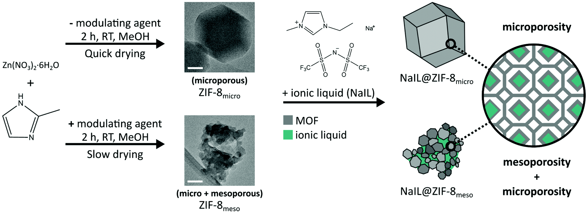 | ||
| Fig. 1 Schematic depicting the synthesis of microcrystalline and mesoporous ZIF-8 and the corresponding IL@MOF composites. Direct reaction of zinc nitrate hexahydrate and 2-methylimidazole in solution gives a microcrystalline powder of ZIF-8. Mesoporous ZIF-8 can be formed by adding n-butylamine as a modulating agent during the synthesis, which leads to a gel-like colloidal suspension. Controlled drying of this suspension at room temperature leads to the formation of the mesoporous ZIF-8. Representative bright-field transmission electron microscopy (BF-TEM) images are shown for both types of samples and discussed later. Scale bars inset are 50 nm. The ionic liquid mixture (Na0.1EMIM0.9)TFSI, abbreviated to NaIL, is then incorporated into the ZIF-8 samples via a capillary action method yielding the NaIL@ZIF-8micro and NaIL@ZIF-8meso composites. The two samples have distinct morphologies: large, regularly shaped particles for NaIL@ZIF-8micro and irregular, smaller particles for NaIL@ZIF-8meso. Due to this morphology, NaIL@ZIF-8meso contains both mesopores (between particles) and micropores (within particles), while NaIL@ZIF-8micro only exhibits the crystallographically defined microporosity, schematically shown on the far right. | ||
Pellet preparation for electrochemical impedance spectroscopy
5 mm diameter pellets of the NaIL@ZIF-8micro and NaIL@ZIF-8meso were pressed at 0.25 Tonnes (125 MPa) for 2 min to achieve a dense pellet, without expulsion of the NaIL solution. The pellet was then sandwiched between two stainless steel electrodes and the impedance measured by EIS. Samples were measured from 25–125 °C, in steps of 20 °C, and three measurements were recorded at each temperature during both heating and cooling sweeps.It has been reported previously that under nonhydrostatic conditions, ZIF-8 can be amorphised by mechanical compression at pressures above 340 MPa.24 Therefore it is important that the pelletisation pressure remains below this limit. In ZIF-4 ([Zn(Im)2], Im = imidazolate), the presence of dimethylformamide in the pores of the MOF shifted the amorphisation from 0.35–0.98 GPa to 2.61–6.43 GPa under hydrostatic conditions.25 Similarly, in another study it was found ZIF-8 impregnated with toluene and 2-propanol, abated the amorphisation of the framework, which retained 80% of its structure and porosity at 1.15 GPa.26 Therefore, the presence of IL in the pores of ZIF-8 is likely to also increase the amorphisation pressure compared to pristine ZIF-8. The low pressure used, along with the presence of IL in the pores reduces the possibility of irreversible structural transitions occurring during pelletisation.
Equipment details
See ESI.†Results and discussion
Characterisation of microporous and hierarchically porous ZIF-8
Samples of ZIF-8 were synthesised as described in the Experimental section and depicted in Fig. 1. A typical reaction of the zinc metal source and 2-methylimidazole in methanol, at a relatively low concentration, yields a microcrystalline powder of ZIF-8. In a similar synthesis, the addition of a modulating agent and a change in the concentrations of the reactants leads to a gel-like colloidal suspension. Controlled drying of this suspension at room temperature, yields a monolith of ZIF-8 which has been shown previously to exhibit a hierarchical porosity of both micropores (from the MOF self-assembly) and mesopores (from the random packing of MOF crystals).19,21,22 These samples are referred to as ZIF-8micro and ZIF-8meso, respectively for the ‘standard’ and ‘modified’ synthesis conditions.XRD patterns (Fig. S1†) of both the ZIF-8micro and ZIF-8meso match with the peak positions and relative intensities of the simulated pattern for ZIF-8 without impurity phases. Significant peak broadening is observed in the ZIF-8meso sample which is likely due to the smaller crystallite size afforded by the modulated synthesis conditions. Crystallite size analysis was carried out on the ZIF-8micro and ZIF-8meso XRD patterns. A silicon standard was measured to obtain the instrumental peak broadening and used to extract crystallite size information from the Pawley refinements of the ZIF-8 samples (Fig. S2 and Table S1†).27 This procedure is described in the equipment details section of the ESI.† ZIF-8micro was estimated to have an average crystallite size of 156 ± 5 nm, with ZIF-8meso exhibiting a much smaller average crystallite size of 19.3 ± 0.9 nm. This is in agreement with the particle sizes shown in the bright-field transmission electron microscopy (BF-TEM) micrographs (Fig. 1).
To further support this, SEM was used to investigate particle size and morphology (Fig. 2). The pristine ZIF-8micro shows a homogeneous distribution of rhombic dodecahedron particles of ∼200–300 nm in size. In contrast, the ZIF-8meso sample shows a wide distribution of less well-defined agglomerates with sizes from ∼100 nm up to a few microns. Although it should be noted that the primary particle size, i.e. the crystallite size, has been shown to be much smaller than this.
 | ||
| Fig. 2 SEM micrographs of all samples: left column: ZIF-8micro, right column: ZIF-8meso, top row: without NaIL incorporation, bottom row: after NaIL incorporation. All scale bars are 1 μm. | ||
In order to establish the filling capacity of the microporous and mesoporous ZIF-8 samples, N2 gas sorption isotherms at 77 K (Fig. S3 and 4†) were measured and subsequent non-linear DFT pore volume analysis (Fig. 3) was carried out as described in the ESI.† IUPAC defines mesopores as pores of intermediate size, with diameters between 2 and 50 nm,28 hence the theoretical capacity was defined as the total pore volume from all pores with diameters smaller than 50 nm. The N2 adsorption results (Fig. S3 and 4†) show intermediate type I-type IV isotherms which are indicative of microporosity at low relative pressures and meso-/macroporosity at high relative pressures. ZIF-8micro demonstrates a BET surface area of 1864.4 m2 g−1 compared to 1298.0 m2 g−1 for ZIF-8meso. This originates from the synthesis conditions which yield nanoparticles of ZIF-8micro from the conventional synthesis and larger agglomerations of ZIF-8meso from the modulated synthesis.
 | ||
| Fig. 3 DFT pore volume analysis from N2 gas sorption data showing the differential pore volumes as a function of pore width for the microporous (blue) and hierarchically porous (orange) samples of ZIF-8. | ||
Pore volume distributions can be extracted from DFT analysis of this gas sorption data with the results shown in Fig. 3. In the ZIF-8micro sample, exclusively micropores are observed with a peak at ∼1.1 nm, as expected based on the crystallographic structure of ZIF-8. By comparison, the ZIF-8meso sample also shows a sharp peak at ∼1.1 nm from this innate microporosity of the framework but additionally, a broad distribution of pore widths is observed in the ∼2–20 nm range, consistent with previous reports.21,22 This confirms that the ZIF-8meso sample is hierarchically porous with both micro and meso-porosity. From this analysis, pore volumes (at <50 nm pore diameter) of 0.64 and 0.88 cm3 g−1 for ZIF-8micro and ZIF-8meso respectively are calculated, which corresponds to a 37.5% increase in pore volume for the ZIF-8meso sample. These experimentally determined pore volumes are estimated to achieve 100% filling of the micro- and mesopores and used to calculate the volume of IL required to fabricate the composite samples. The gas sorption details are collated in Table 1.
| Sample | S BET/m2 g−1 | V micro+meso/cm3 g−1 | d micro/nm | d meso/nm |
|---|---|---|---|---|
| ZIF-8micro | 1864.4 | 0.64 | 1.09 | — |
| ZIF-8meso | 1298.0 | 0.88 | 1.09 | 8.63 |
| NaIL@ZIF-8micro | 8.3 | 0.00 | — | — |
| NaIL@ZIF-8meso | 18.5 | 0.06 | — | 18.59 |
Characterisation of IL@MOF composites
(Na0.1EMIM0.9)TFSI (abbreviated to NaIL) was the salt-in-IL system chosen to infiltrate into the MOF, as the sodium salt introduces Na+ as a charge carrier relevant for sodium ion batteries.12 This system has been previously studied with microcrystalline samples of ZIF-8 in our previous work.3 NaIL was incorporated in the pores of both microporous and mesoporous samples of ZIF-8 as described in the Experimental section and depicted in Fig. 1, with the resulting composites being referred to as NaIL@ZIF-8micro and NaIL@ZIF-8meso.It should be noted that the pore apertures for the 6-ring windows of the sodalite cages of ZIF-8 have a diameter of ∼0.34 nm,29 whilst the molecular dimensions of the EMIM TFSI cation and anion are expected to be approximately 0.8 × 0.5 nm and 0.6 × 0.9 nm respectively.30 The ability of ZIF-8 to incorporate guest molecules with kinetic diameters greater than the window size is consistent with both computational and experimental studies on ZIF-8.31–34 This has been attributed to the flexibility of the ZIF-8 structure through which the imidazolate linkers can rotate upon guest adsorption and is referred to as a ‘swing effect’.
XRD patterns (Fig. S1†) of both the NaIL@ZIF-8micro and NaIL@ZIF-8meso show minor variations in peak intensities after incorporation of the NaIL solution, consistent with the literature and demonstrating the retention of the ZIF-8 structure.7 Furthermore, the particle sizes and morphology of both samples are not affected by NaIL incorporation (Fig. 2), with additional SEM images of all samples shown in the ESI (Fig. S5†).
Changes in the electronic interactions were also identified by TGA, which shows a significant reduction in thermal stabilities of the composites compared with the pristine ZIF-8 samples (Fig. S6†). Decomposition temperatures (Td) were approximated as the onset of the first derivative of the TGA curves for comparison between all the samples and to avoid overestimating Td. Td of the pristine ZIF-8micro and ZIF-8meso samples were measured as 605 °C and 581 °C respectively, consistent with the literature.35,36 In the composite samples, the decomposition temperatures are shifted to 432 °C for both NaIL@ZIF-8micro and NaIL@ZIF-8meso. This reduction in thermal stability is consistent with other IL@ZIF-8 composites and is attributed to the IL/MOF interactions.37–41
After incorporation of the NaIL solution, the BET surface area of the samples decreased significantly from 1864.4 m2 g−1 to 8.3 m2 g−1 for NaIL@ZIF-8micro and from 1298.0 m2 g−1 for NaIL@ZIF-8meso to 18.5 m2 g−1 (Table 1). This suggests the micro- and mesopores are no longer accessible.
To quantify the amount of NaIL which has been successfully incorporated into the ZIF-8 pores, the composite samples were digested in a mixture of 35% DCl in D2O and DMSO-d6 and their proton (1H) NMR spectra recorded (Fig. S7–9†). By integrating the assigned 1H NMR signals of the 2-MeIm from the ZIF-8 framework and EMIM from the IL, a ratio can be compared. For the microporous composite, the ratio of 2-MeIm![[thin space (1/6-em)]](https://www.rsc.org/images/entities/char_2009.gif) :EMIM was found to be 4:1 whilst for the mesoporous composite, the ratio was found to be 2.86:1. This 40% difference in 2-MeIm:EMIM ratio is in good agreement with the 37.5% difference in pore volume for the ZIF-8micro and ZIF-8meso samples. Results from elemental analysis of both the pristine and composite samples can be found in Table S2.† Inductively coupled plasma – optical emission spectrometry (ICP-OES) was used to quantify the Zn and S ratios directly. Zn:S ratios were found to be 1.52:1 and 1.09:1 (S/Zn of 0.658 and 0.917) for NaIL@ZIF-8micro and NaIL@ZIF-8meso respectively which again corresponds to a 40% increase in IL in the mesoporous composite compared to the microcrystalline composite.
:EMIM was found to be 4:1 whilst for the mesoporous composite, the ratio was found to be 2.86:1. This 40% difference in 2-MeIm:EMIM ratio is in good agreement with the 37.5% difference in pore volume for the ZIF-8micro and ZIF-8meso samples. Results from elemental analysis of both the pristine and composite samples can be found in Table S2.† Inductively coupled plasma – optical emission spectrometry (ICP-OES) was used to quantify the Zn and S ratios directly. Zn:S ratios were found to be 1.52:1 and 1.09:1 (S/Zn of 0.658 and 0.917) for NaIL@ZIF-8micro and NaIL@ZIF-8meso respectively which again corresponds to a 40% increase in IL in the mesoporous composite compared to the microcrystalline composite.
To probe the nanoscale morphology and the spatial distribution of the ionic liquid within the pore network of the sample, we use BF-TEM imaging and scanning transmission electron microscope energy dispersive X-ray spectroscopy (STEM-EDX). BF-TEM micrograph comparison of NaIL@ZIF-8micro and NaIL@ZIF-8meso is shown in the schematic in Fig. 1, 4 and Fig. S10.† Similar to the SEM results, BF-TEM confirms different nanoscale morphologies of the two samples. ZIF-8micro has a well-defined shape and relatively large crystallite size of ∼200–300 nm, while ZIF-8meso is much less uniform and the primary ‘building block’ particle is much smaller. Some voids inside of the material can also be seen in the ZIF-8meso sample, with sizes corresponding to the 2–50 nm range of mesopores observed in the DFT pore volume analysis.
 | ||
| Fig. 4 BF-TEM micrographs showing different nanoscale morphologies of the samples. Left: NaIL@ZIF-8micro, right: NaIL@ZIF-8meso. Both scale bars are 100 nm. | ||
STEM-EDX was employed to explore the possibility of mapping the distribution of the ionic liquid within the composite. As both the MOF and IL have most of the elements in common and some overlapping X-ray lines, the most useful parameter characterising the NaIL distribution from STEM-EDX is the S/Zn ratio, calculated using the S Kα and Zn Kα X-ray lines. In this way, overlapping X-ray lines are avoided, while still probing elements unique to the MOF (Zn) and IL (S). Spatially resolved maps of the S/Zn ratio are shown in Fig. 5. The F/Zn ratio could also be used as fluorine is unique to the ionic liquid, but due to the low atomic number of fluorine and lower X-ray energy of F Kα line, the quantification is less precise. F/Zn ratio maps have been shown in Fig. S11.†
 | ||
| Fig. 5 Top row: ADF-STEM images of both MOF types. Bottom row: S/Zn ratio maps for the regions highlighted with orange squares. Pixel sizes of the S/Zn ratio maps are 5 nm. Note the change of colour scale between NaIL@ZIF-8micro and NaIL@ZIF-8meso EDX maps. | ||
The S/Zn ratio maps show that the ‘micro’ and ‘meso’ samples contain quite different amounts of the ionic liquid. The average ratio across the whole scan area is almost an order of magnitude different between them: (0.037 ± 0.004) for NaIL@ZIF-8micro and (0.334 ± 0.019) for NaIL@ZIF-8meso. The error here is the standard deviation of a few scans of different, previously unexposed regions for each sample. Moreover, both samples show different kinds of inhomogeneity in the spatial distribution of S/Zn ratio. In the ‘micro’ specimen, there are areas of higher S/Zn ratio in regions corresponding to what could be pockets between particles (highlighted by the red arrows in Fig. 5), where the ionic liquid could be trapped. On the other hand, the map of the NaIL@ZIF-8meso sample shows that S/Zn ratio is higher further away from the edge of the particle cluster. As discussed before, ZIF-8meso consists of 20–50 nm particles connected quite loosely and exhibits porosity in the similar size range. Therefore, ZIF-8meso can hold a significant amount of the ionic liquid in said voids, and with the electron beam passing through a thick portion of the sample, it will pass through the mesopores, causing the big disparity in the overall S/Zn ratio when compared to ZIF-8micro. Near the edge of the particle clusters, the sample thickness is lower and so, there are fewer IL-containing voids along the beam direction as well as the voids are likely to be open to the environment and hence not holding the ionic liquid as well. These mesoporous interparticle voids are absent in the NaIL@ZIF-8micro, where most of the porosity is either the micropores (<2 nm) or macropores between the ∼200 nm particles. The large disparity between S/Zn ratio measured by STEM-EDX (0.037 and 0.334 for micro and meso samples respectively) and elemental analysis (0.658 and 0.917) can be attributed to the presence of ionic liquid in the macroporosity of the samples. The contents of the macropores would be measured by ICP-OES, but are not seen in STEM-EDX as the particle agglomerates measured here are relatively small and the porosity of >50 nm scale is not probed. It should also be noted that limitations due to beam damage mean that it is extremely challenging to determine the ionic liquid distribution in micropores or channels below a few nanometres in size and such an attempt is beyond the scope of this work.
Ionic conductivity properties of IL@MOF composites
Temperature dependent alternating-current (AC) electrochemical impedance spectroscopy (EIS) was used to investigate the ionic conductivity properties of the microporous and mesoporous composites. The temperature-measurement profiles are shown in Fig. S12† with long hold times to ensure the sample has had sufficient time for thermal equilibration and three repeat measurements recorded at each temperature. Impedance spectra are recorded on both heating and cooling to check for hysteresis. Nyquist plots of both samples are shown in Fig. 6a and b with both samples showing a typical semi-circular arc at higher frequencies and tail at lower frequencies, characteristic of an ionic conductor. At temperatures above 85 °C, only a tail is observed. Such systems are commonly modelled as an equivalent RC circuit which can be fit to the experimental data. The RC circuit chosen to fit this data is shown in Fig. 6c, takes the form of a modified Randles circuit which describes the impedance of an ideal ion conductor with diffusion limited conductivity. The results of the fit are shown in Fig. 6a and b. A detailed description of the fitting is explained in the ESI,† with the fitting results shown in Fig. S13 and 14† and fitting parameters shown in Tables S3 and 4.†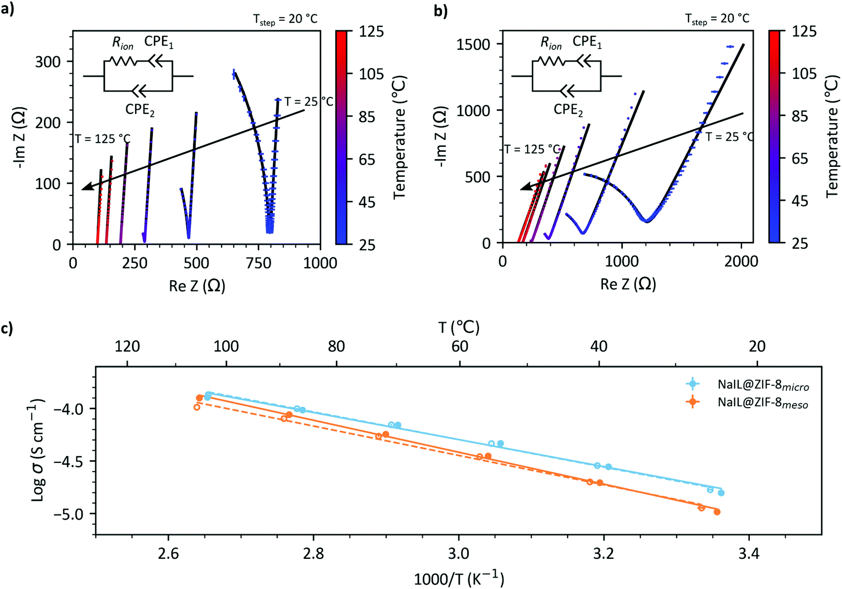 | ||
| Fig. 6 Nyquist plots from EIS measurement of (a) NaIL@ZIF-8micro and (b) NaIL@ZIF-8meso from 25–125 °C. Only the electrochemical impedance spectra from cooling are shown for clarity. Error bars are taken from the standard deviation of three measurements and the average data is shown. The black lines correspond to the fit data from the equivalent RC circuit used to model the data (inset), where CPE corresponds to a constant phase element. An Arrhenius type plot of log conductivity against inverse temperature is shown in (c) for the NaIL@ZIF-8micro (blue) and NaIL@ZIF-8meso (orange) samples. The dotted lines and open circles represent impedance measurements taken when cooling from 125 to 25 °C and solid lines and closed circles when heating. Lines are simple linear fits for the data presented. | ||
From the Nyquist plots, the values for ionic conductivity can be extracted at each temperature as described in the ESI† and shown in Fig. 6c. It is apparent that the ionic conductivities of NaIL@ZIF-8micro are consistently higher than for NaIL@ZIF-8meso over the temperature range (25–125 °C). At 25 °C, the room temperature ionic conductivities are 8.4 × 10⁻⁶ and 1.6 × 10⁻⁵ S cm−1 for NaIL@ZIF-8meso and NaIL@ZIF-8micro, respectively. However, both are two orders of magnitude below bulk NaIL which has room temperature ionic conductivities of 5.3 × 10⁻⁵ S cm−1,12 which is explained by the coulombic interaction with the pore walls16 and is a common feature of IL@MOF composites.7,13
Activation energies can be derived from a linear fit of ln(σT) vs. 1000/T, as shown in Fig. S15.† The activation energies for ion conduction on cooling were calculated to be: 0.28 ± 0.01 eV and 0.28 ± 0.01 eV for NaIL@ZIF-8micro and NaIL@ZIF-8meso respectively whilst for heating these were determined to be 0.29 ± 0.01 eV and 0.29 ± 0.01 eV respectively. These results strongly suggest that the mechanism for ion conduction is the same in both samples and as the NaIL@ZIF-8micro sample lacks mesopores, the ion conduction is likely to be occurring primarily through the micropores. Micropores provide ideal, long-range, continuous pathways for ion conduction and therefore excellent ion transport properties.
Although the RT ionic conductivities are typically reported in S cm−1 to account for the pellet dimensions, this generally applies to dense pellets with a homogeneous transport ion distribution. An additional consideration for porous guest–host structures is the pellet pore volumes. To that effect, the RT ionic conductance per total pellet pore volume (i.e. micro- and mesopore volume) as well as the RT ionic conductance per micropore volume were calculated (Table 2) in order to gain insight into the relative influence of the micro- and mesopores. If there was truly a limited contribution from the mesopores in the hierarchically porous composite and the micropores contribute dominantly to the overall ionic conductivity, then the RT ionic conductance per unit of micropore volume should be similar for both samples. When taking into account the total pore volume of each pellet, values of 1.72 × 10⁻¹ and 7.70 × 10⁻² S cm−3 for the NaIL@ZIF-8micro and NaIL@ZIF-8meso samples respectively were calculated. This result suggests that for a given pore volume, the microporous IL@MOF composite still outperforms with hierarchically porous IL@MOF composite. However, when assuming that the micropores dominate the ionic conductivity and the mesopores do not contribute to the overall ionic conductivity, values of 1.77 × 10⁻¹ and 1.73 × 10⁻¹ S cm−3 for the NaIL@ZIF-8micro and NaIL@ZIF-8meso samples respectively, were calculated. This corresponds to a small difference of −2% when considering only the micropore volume, compared to a much larger difference of −64% when accounting for the total pore volume. This supports the conclusions that the micropores contribute predominantly to the overall ionic conductivity of the samples.
| Parameter | Unit | NaIL@ZIF-8micro | NaIL@ZIF-8meso |
|---|---|---|---|
| Pellet mass | g | 1.07 × 10⁻² | 1.15 × 10⁻² |
| Micropore + mesopore volume | cm3 | 6.85 × 10⁻³ | 1.01 × 10⁻² |
| Micropore volume | cm3 | 6.67 × 10⁻³ | 4.49 × 10⁻³ |
| Mesopore volume | cm3 | 1.82 × 10⁻⁴ | 5.59 × 10⁻³ |
| RT ionic conductivity | S cm−1 | 1.6 × 10⁻⁵ | 8.4 × 10⁻⁶ |
| RT pellet resistance | Ω | 849.7 | 1289.4 |
| RT ionic conductance per total pore volume | S cm−3 | 1.72 × 10⁻¹ | 7.70 × 10⁻² |
| RT ionic conductance per micropore volume | S cm−3 | 1.77 × 10⁻¹ | 1.73 × 10⁻¹ |
As the nature of the mesopores originates from the random packing of the 20–50 nm ZIF-8 particles and the interparticle voids that are generated between them, the pathways that are generated are likely to be discontinuous and tortuous. This discontinuity means that there are isolated mesopores which contain proportionally more bulk-like NaIL than in the micropores due to the difference in surface to volume ratio. This raises the question of whether there is significant transfer between the mesoporous and microporous regimes which could affect the overall ionic conductivity. Although transfer from a bulk-like region within a mesopore to a much more confined micropore seems unfavourable, further work is required to establish whether the energy barrier for this process can be overcome or whether other effects such as the formation of a space charge layer interfere with the transfer. Comparison with an ordered, percolating mesoporous network in a hierarchically porous IL@MOF composite may provide some insight into the importance of the continuity of the mesoporous pathways and indirectly, evidence for transfer between the microporous and mesoporous regimes.
A classic example of the effect of a percolating network on ionic conductivity is the conductor/insulator composite system AgI:Al2O3.42 At a low volume fraction of the insulating phase, isolated particles form which do not contribute much to the overall conductivity; as the volume fraction increases, continuous paths are produced and the ionic conductivity increases significantly.42
Comparison with other systems
These results are put into context with those from a selection of IL@MOF composites and traditional solid-state electrolytes (Table 3). The conductivities reported here fall into the middle of those reported for a range of ionic liquids, salts and MOFs (10−6 to 10−3 S cm−1), and possess activation energies similar to other salt-in-IL@MOF systems. They have however been achieved without optimisation of the pellet pressing/sintering and without any conformal electrodes on the surface of the pellet to ensure good electrical contact. Such factors have been shown to have an impact of orders of magnitude for traditional solid-state electrolyte systems.43–45| Type | Salt | Solvent | Solid matrix | Room temperature ionic conductivity/S cm−1 | Activation energy /eV | Ref. |
|---|---|---|---|---|---|---|
| IL@MOF composites | — | [EMIM][TFSI] | ZIF-8 | *3.2 × 10⁻⁵ | 0.35 | 7, 13 and 14 |
| — | [EMIM][N(CN)2] | PCN-777 | 4.4 × 10⁻³ | 0.20 | 6 | |
| LiTFSI | [EMIM][TFSI] | ZIF-8 | *5.6 × 10⁻⁶ | 0.59 | 7, 14 | |
| NaTFSI | [EMIM][TFSI] | ZIF-8 | 2 × 10⁻⁴ | 0.26 | 3 | |
| NaBF4 | [EMIM][BF4] | MIL-101-SO3Na | 1.79 × 10⁻³ | 0.20 | 54 | |
| NaTFSI | [EMIM][TFSI] | ZIF-8 micro | 1.6 × 10⁻⁵ | 0.29 | This work | |
| NaTFSI | [EMIM][TFSI] | ZIF-8 meso | 8.4 × 10⁻⁶ | 0.29 | This work | |
| Traditional solid-state electrolytes | — | — | Na3Zr2Si2PO12 | 3.3 × 10⁻⁴ | 0.27 | 48 |
| — | — | Na3.4Sc2Si0.4P2.6O12 | 6.9 × 10⁻⁴ | 0.33 | 49 | |
| — | — | Na3.1Zr1.95Mg0.05Si2PO12 | 3.5 × 10⁻³ | 0.25 | 50 | |
| — | — | Na-β′′-alumina | 1.6 × 10⁻³ | 0.41 | 51 |
In the pure IL@MOF systems, [EMIM][TFSI]@ZIF-8 is observed to have higher conductivities than the corresponding lithium and sodium salt-in-IL systems, as expected due to the strong inter-ion interactions. [EMIM][N(CN)2]@PCN-777 was also chosen for comparison as PCN-777 is an innately mesoporous MOF with the structure [Zr6O4(OH)10(H2O)6(TATB)2] (where H3TATB = 4,4′,4′′-s-triazine-2,4,6-triyl-tribenzoic acid). The combination of bulky TATB3− ligands and [Zr6O4(OH)4(CO2)12] clusters lead to mesoporous cages with diameters of ∼3.5 nm which maximises the amount of IL occupying the ‘bulk-like’ region of the pores, thus achieving ionic conductivities which are 2 orders of magnitude greater than other microporous IL@MOF composites.6
Comparisons to traditional sodium ion conducting solid state electrolytes are also made with the NASICON family of materials (with the general formula Na1+xZr2SixP3−xO12) and sodium beta alumina as these are both promising and extensively studied candidate for sodium ion batteries.46–51 Incremental improvements over the last 40 years have led to the increase in room temperature ionic conductivities from 10–4 S cm−1 in undoped Na3Zr2Si2PO12, to 10–3 S cm−1 with various structural substitution and optimisation of the microstructure e.g. by using nanoparticle precursors.43,48 Issues that plague true solid-state electrolytes such as needing incredibly high densities and limitations of grain boundary resistances are less of an issue in pseudo-solid state electrolyte systems.
Not only does the individual performance of the solid-state electrolyte have to be outstanding to justify adoption, but the systems compatibility with the electrodes, operating temperatures and operating voltages must also be considered. One of the key advantages of the salt-in-IL@MOF systems is the chemical versatility of both the IL and MOF components can be varied in order to ensure compatibility with the other battery components and conditions. Recently, reports on the full battery performance of lithium salt based IL@MOF composites have been demonstrated in the literature for a range of configurations such as Li|LiIL@MOF|Li symmetric cells, Li|LiIL@MOF|LiFePO4 and Li|LiIL@MOF|LiCoO2 cells.2,4,52 These early results show promising electrochemical performance, with little capacity degradation upon cycling and good thermal stability.2,4,52
From the comparisons made here, we have seen that the nature of the MOF pores has a substantial impact on the ionic conductivities of the composite material. Perhaps the ideal MOF structure for such a composite would consist of an ordered hierarchical porosity with micro- and meso/macroporous pathways which are long-range and continuous on all length scales. In theory, this could be achieved innately by a mixed linker MOF or post-synthetically by non-random packing of MOF particles to form an ordered array. One potential route would be to utilise predefined architectures on which to template MOF formation as has been used to generate hierarchically porous MOF structures for water/ethanol separation from meso/macroporous aerogel parent structures.53
Conclusions
We have successfully fabricated a hierarchically porous IL@MOF composite containing both meso- and micropores from ZIF-8 synthesised via a sol–gel procedure. This novel material was compared with the analogous composite from a microcrystalline sample of ZIF-8 with only micropores. Results showed that the NaIL@ZIF-8meso contained ∼40% more IL than the NaIL@ZIF-8micro composite due to the increased volumetric capacity afforded by the mesopores. Despite this increased loading of the NaIL@ZIF-8meso composite, the ionic conductivities were found to be consistently lower than the analogous microcrystalline composite. These results demonstrate the significance of ion conduction pathways which are long-range, continuous, and have minimal tortuosity akin to the microporous pathways formed from the self-assembly of metal nodes and organic linker of a typical microcrystalline MOF.There have been a fascinating range of hierarchical MOF structures which have been recently reported, including the control of both density and porosity in hierarchically porous UiO-66 monoliths;55 templating hierarchical porosity in MOFs from ordered metal oxide precursors;53 and hierarchically porous MOF aerogels via supercritical CO2 extraction.56 Further work is being carried out towards controlling the mesoporous architectures in hierarchically porous MOFs to improve ion transport properties as well as the testing their practical applications in batteries as important future directions.
Conflicts of interest
There are no conflicts to declare.Acknowledgements
T. D. B. thanks the Royal Society for both a University Research Fellowship (UF150021) and a research grant (RSG\R1\180395). T. D. B. also gratefully acknowledges the University of Canterbury Te Whare Wānanga o Waitaha, New Zealand, for a University of Cambridge Visiting Canterbury Fellowship, and the Leverhulme Trust for a Philip Leverhulme Prize. J. M. T, C. D. and J. K. M. acknowledge funding from NanoDTC EPSRC Grant EP/L015978/1. J. K. M. also acknowledges funding from the Cambridge Trust. S. E. D. acknowledges funding from the Winton Programme for the Physics of Sustainability. R. T. acknowledges the funding from China Scholarship Council. Q. S. acknowledges the funding from EPSRC Centre CAM-IES and ERC (NanoMMES, 851272). N. D. K. acknowledges PhD funding from the EPSRC Grant EP/R513180/1. J. M. T. would also like to thank Jack Hodkinson and Adam Lovett for their helpful discussions on the fitting of the electrochemical impedance spectra as well as Vahid Nozari and Lothar Wondraczek for further helpful discussions. J. K. M. would like to thank S. M. Collins for discussions on possible TEM approaches.References
- F. P. Kinik, A. Uzun and S. Keskin, ChemSusChem, 2017, 10, 2842–2863 CrossRef CAS.
- N. Chen, Y. Li, Y. Dai, W. Qu, Y. Xing, Y. Ye, Z. Wen, C. Guo, F. Wu and R. Chen, J. Mater. Chem. A, 2019, 7, 9530–9536 RSC.
- V. Nozari, C. Calahoo, J. M. Tuffnell, P. Adelhelm, K. Wondraczek, S. E. Dutton, T. D. Bennett and L. Wondraczek, Sci. Rep., 2020, 10, 3532 CrossRef CAS.
- Z. Wang, R. Tan, H. Wang, L. Yang, J. Hu, H. Chen and F. Pan, Adv. Mater., 2018, 30, 1–7 Search PubMed.
- C. Lu and X. Chen, J. Power Sources, 2020, 448, 227587 CrossRef CAS.
- Y. Yoshida, K. Fujie, D. W. Lim, R. Ikeda and H. Kitagawa, Angew. Chem., Int. Ed., 2019, 58, 10909–10913 CrossRef CAS.
- K. Fujie, R. Ikeda, K. Otsubo, T. Yamada and H. Kitagawa, Chem. Mater., 2015, 27, 7355–7361 CrossRef CAS.
- A. Basile, A. I. Bhatt and A. P. O'Mullane, Nat. Commun., 2016, 7, 1–11 Search PubMed.
- V. Lesch, Z. Li, D. Bedrov, O. Borodin and A. Heuer, Phys. Chem. Chem. Phys., 2016, 18, 382–392 RSC.
- M. Shimizu, H. Usui and H. Sakaguchi, Phys. Chem. Chem. Phys., 2016, 18, 5139–5147 RSC.
- J. C. Lassègues, J. Grondin and D. Talaga, Phys. Chem. Chem. Phys., 2006, 8, 5629–5632 RSC.
- D. Monti, E. Jónsson, M. R. Palacín and P. Johansson, J. Power Sources, 2014, 245, 630–636 CrossRef CAS.
- K. Fujie, K. Otsubo, R. Ikeda, T. Yamada and H. Kitagawa, Chem. Sci., 2015, 6, 4306–4310 RSC.
- Y. Yoshida and H. Kitagawa, ACS Sustainable Chem. Eng., 2019, 7, 70–81 CrossRef CAS.
- Y. Chen, Z. Hu, K. M. Gupta and J. Jiang, J. Phys. Chem. C, 2011, 115, 21736–21742 CrossRef CAS.
- B. Coasne, L. Viau and A. Vioux, J. Phys. Chem. Lett., 2011, 2, 1150–1154 CrossRef CAS.
- L. Shen, H. B. Wu, F. Liu, J. L. Brosmer, G. Shen, X. Wang, J. I. Zink, Q. Xiao, M. Cai, G. Wang, Y. Lu and B. Dunn, Adv. Mater., 2018, 30, 1707476 CrossRef.
- J. Hou, A. F. Sapnik and T. D. Bennett, Chem. Sci., 2020, 11, 310–323 RSC.
- T. Tian, Z. Zeng, D. Vulpe, M. E. Casco, G. Divitini, P. A. Midgley, J. Silvestre-Albero, J. C. Tan, P. Z. Moghadam and D. Fairen-Jimenez, Nat. Mater., 2018, 17, 174–179 CrossRef CAS.
- J. Cravillon, R. Nayuk, S. Springer, A. Feldhoff, K. Huber and M. Wiebcke, Chem. Mater., 2011, 23, 2130–2141 CrossRef CAS.
- T. Tian, J. Velazquez-Garcia, T. D. Bennett and D. Fairen-Jimenez, J. Mater. Chem. A, 2015, 3, 2999–3005 RSC.
- B. Bueken, N. Van Velthoven, T. Willhammar, T. Stassin, I. Stassen, D. A. Keen, G. V. Baron, J. F. M. Denayer, R. Ameloot, S. Bals, D. De Vos and T. D. Bennett, Chem. Sci., 2017, 8, 3939–3948 RSC.
- H. H. M. Yeung, A. F. Sapnik, F. Massingberd-Mundy, M. W. Gaultois, Y. Wu, D. A. X. Fraser, S. Henke, R. Pallach, N. Heidenreich, O. V. Magdysyuk, N. T. Vo and A. L. Goodwin, Angew. Chem., Int. Ed., 2019, 58, 566–571 CrossRef CAS.
- K. W. Chapman, G. J. Halder and P. J. Chupas, J. Am. Chem. Soc., 2009, 131, 17546–17547 CrossRef CAS.
- T. D. Bennett, P. Simoncic, S. A. Moggach, F. Gozzo, P. MacChi, D. A. Keen, J. C. Tan and A. K. Cheetham, Chem. Commun., 2011, 47, 7983–7985 RSC.
- A. S. Poryvaev, D. M. Polyukhov and M. V. Fedin, ACS Appl. Mater. Interfaces, 2020, 12, 16655–16661 CrossRef CAS.
- G. S. Pawley, J. Appl. Crystallogr., 1981, 14, 357–361 CrossRef CAS.
- IUPAC Compendium of Chemical Terminology, ed. A. D. McNaught and A. Wilkinson, Blackwell Scientific Publications, 2nd edn, 1997 Search PubMed.
- F. Coudert, ChemPhysChem, 2017, 18, 2732–2738 CrossRef CAS.
- A. Elbourne, S. McDonald, K. Voïchovsky, F. Endres, G. G. Warr and R. Atkin, ACS Nano, 2015, 9, 7608–7620 CrossRef CAS.
- K. Zhang, R. P. Lively, C. Zhang, R. R. Chance, W. J. Koros, D. S. Sholl and S. Nair, J. Phys. Chem. Lett., 2013, 4, 3618–3622 CrossRef CAS.
- R. J. Verploegh, S. Nair and D. S. Sholl, J. Am. Chem. Soc., 2015, 137, 15760–15771 CrossRef CAS.
- X. Wu, J. Huang, W. Cai and M. Jaroniec, RSC Adv., 2014, 4, 16503–16511 RSC.
- S. A. Moggach, T. D. Bennett and A. K. Cheetham, Angew. Chem., Int. Ed., 2009, 48, 7087–7089 CrossRef CAS.
- J. P. Mehta, T. Tian, Z. Zeng, G. Divitini, B. M. Connolly, P. A. Midgley, J.-C. Tan, D. Fairen-Jimenez and A. E. H. Wheatley, Adv. Funct. Mater., 2018, 28, 1705588 CrossRef.
- Y. Pan, Y. Liu, G. Zeng, L. Zhao and Z. Lai, Chem. Commun., 2011, 47, 2071–2073 RSC.
- M. Zeeshan, S. Keskin and A. Uzun, Polyhedron, 2018, 155, 485–492 CrossRef CAS.
- F. P. Kinik, C. Altintas, V. Balci, B. Koyuturk, A. Uzun and S. Keskin, ACS Appl. Mater. Interfaces, 2016, 8, 30992–31005 CrossRef CAS.
- B. Koyuturk, C. Altintas, F. P. Kinik, S. Keskin and A. Uzun, J. Phys. Chem. C, 2017, 121, 10370–10381 CrossRef CAS.
- M. Mohamedali, H. Ibrahim and A. Henni, Chem. Eng. J., 2018, 334, 817–828 CrossRef CAS.
- M. Zeeshan, V. Nozari, S. Keskin and A. Uzun, Ind. Eng. Chem. Res., 2019, 58, 14124–14138 CrossRef CAS.
- J. Maier, J. Phys. Chem. Solids, 1985, 46, 309–320 CrossRef CAS.
- A. Jalalian-Khakshour, C. O. Phillips, L. Jackson, T. O. Dunlop, S. Margadonna and D. Deganello, J. Mater. Sci., 2020, 55, 2291–2302 CrossRef.
- S. Wong, P. J. Newman, A. S. Best, K. M. Nairn, D. R. MacFarlane and M. Forsyth, J. Mater. Chem., 1998, 8, 2199–2203 RSC.
- C. J. Leo, G. V. Subba Rao and B. V. R. Chowdari, Solid State Ionics, 2003, 159, 357–367 CrossRef CAS.
- Y. Meesala, A. Jena, H. Chang and R. S. Liu, ACS Energy Lett., 2017, 2, 2734–2751 CrossRef CAS.
- K. Arbi, S. Mandal, J. M. Rojo and J. Sanz, Chem. Mater., 2002, 14, 1091–1097 CrossRef CAS.
- A. G. Jolley, G. Cohn, G. T. Hitz and E. D. Wachsman, Ionics, 2015, 21, 3031–3038 CrossRef CAS.
- M. Guin, F. Tietz and O. Guillon, Solid State Ionics, 2016, 293, 18–26 CrossRef CAS.
- S. Song, H. M. Duong, A. M. Korsunsky, N. Hu and L. Lu, Sci. Rep., 2016, 6, 1–10 CrossRef.
- M. Bay, M. Wang, R. Grissa, M. V. F. Heinz, J. Sakamoto and C. Battaglia, Adv. Energy Mater., 2020, 10, 1902899 CrossRef CAS.
- C. Sun, J. H. Zhang, X. F. Yuan, J. N. Duan, S. W. Deng, J. M. Fan, J. K. Chang, M. S. Zheng and Q. F. Dong, ACS Appl. Mater. Interfaces, 2019, 11, 46671–46677 CrossRef CAS.
- J. Reboul, S. Furukawa, N. Horike, M. Tsotsalas, K. Hirai, H. Uehara, M. Kondo, N. Louvain, O. Sakata and S. Kitagawa, Nat. Mater., 2012, 11, 717–723 CrossRef CAS.
- Q. Xu, F. Yang, X. Zhang, J. R. Li, J. F. Chen and S. Zhang, ChemElectroChem, 2020, 7, 183–190 CrossRef CAS.
- B. M. Connolly, M. Aragones-Anglada, J. Gandara-Loe, N. A. Danaf, D. C. Lamb, J. P. Mehta, D. Vulpe, S. Wuttke, J. Silvestre-Albero, P. Z. Moghadam, A. E. H. Wheatley and D. Fairen-Jimenez, Nat. Commun., 2019, 10, 1–11 CrossRef CAS.
- L. Li, S. Xiang, S. Cao, J. Zhang, G. Ouyang, L. Chen and C. Y. Su, Nat. Commun., 2013, 4, 1–9 CAS.
Footnote |
| † Electronic supplementary information (ESI) available. See DOI: 10.1039/d0dt02576c |
| This journal is © The Royal Society of Chemistry 2020 |