
 Open Access Article
 This Open Access Article is licensed under a Creative Commons Attribution-Non Commercial 3.0 Unported Licence
Composition-tuned metal–organic thin-film structures based on photoswitchable azobenzene by ALD/MLD
Aida
Khayyami
 ,
Anish
Philip
,
Jenna
Multia
and
Maarit
Karppinen
*
,
Anish
Philip
,
Jenna
Multia
and
Maarit
Karppinen
*
Department of Chemistry and Materials Science, Aalto University, FI-00076 Espoo, Finland. E-mail: maarit.karppinen@aalto.fi
First published on 21st July 2020
Abstract
We demonstrate the fabrication of in-situ crystalline thin films of various azobenzene (AZO) based metal-organic structures using the atomic/molecular layer deposition (ALD/MLD) technique; these are highly intriguing materials as azobenzene is one of the prototype organic molecules experiencing photoisomerization. Our Li-, Ca and Fe-AZO thin films deposited from Li(thd) (thd = 2,2,6,6-tetramethyl-3,5-heptanedione), Ca(thd)2, FeCl3 and azobenzene-4,4′-dicarboxylic acid precursors in the temperature range of 250–360 °C exhibit metal-AZO structures not known from bulk samples. In all these structures, the AZO linker molecules are free to undergo the characteristic trans-cis photoisomerization reaction upon UV (360 nm) irradiation. However, this lowers the degree of crystallinity. To address the issue, we investigate hetero-organic structures where TPA (terephthalic acid) is used as another linker component together with AZO. This allows the trans–cis reaction of the AZO moieties to occur without compromising the film crystallinity. Finally, we demonstrate the growth of MOF-on-MOF type Ca-ADA@Ca-TPA thin films also showing the efficient photoisomerization reaction.
Introduction
Crystalline metal–organic materials composed of metal ions linked together via organic ligands, i.e. so-called coordination polymers (CPs) and metal–organic frameworks (MOFs), have been leading the research forefront already for years.1,2 The wide range of the possible building blocks has made the CP/MOF material family as a kind of chemists’ dream. These materials can be made mechanically flexible and highly porous and tuned by design for multiple electrical, optical, magnetic, and chemical functionalities. In addition, different types of hybrid structures have been made by (i) conjugating an MOF material with functional nanoparticles, (ii) mixing two different metal species or organic linkers within the metal–organic structure for a bimetallic or hetero-organic MOF, or (iii) growing different metal–organic materials on top of each other for MOF@MOF-type heterostructures.3–8Among the organic linkers, azobenzene (AZO; –C6H4–N![[double bond, length as m-dash]](https://www.rsc.org/images/entities/char_e001.gif) N–C6H4–) is one of the most intriguing choices as it can undergo a photoisomerization about its NN bond from the longer trans isomer to the shorter cis isomer upon ultraviolet (UV) light irradiation, and thereby function as a photoswitch for a dimension change in the MOF lattice.9,10 However, in most of the cases the metal–organic crystal lattice actually poses serious geometrical constraints for the trans–cis transformation to occur efficiently; in practice, the most promising candidates are those MOF structures in which the photoactive organic moiety is diluted with a non-active organic moiety.11–13
N–C6H4–) is one of the most intriguing choices as it can undergo a photoisomerization about its NN bond from the longer trans isomer to the shorter cis isomer upon ultraviolet (UV) light irradiation, and thereby function as a photoswitch for a dimension change in the MOF lattice.9,10 However, in most of the cases the metal–organic crystal lattice actually poses serious geometrical constraints for the trans–cis transformation to occur efficiently; in practice, the most promising candidates are those MOF structures in which the photoactive organic moiety is diluted with a non-active organic moiety.11–13
Atomic/molecular layer deposition (ALD/MLD) is a state-of-the-art technique for the fabrication of crystalline metal–organic thin films from gaseous metal-bearing and organic precursors.14–17 In this method, ALD (atomic layer deposition) pulses of the chosen metal precursor are combined with the MLD (molecular layer deposition) pulses of the organic precursor. This enables the in situ growth of the metal–organic thin film with atomic/molecular level precision for the film thickness and composition.18–20 Most importantly, it should be uniquely suited for the introduction of multiple metal or organic components, i.e. composition tuning. While being straightforward in principle, this has not yet been challenged in practice with any MOF-like materials. A somewhat similar layer-engineering/mixing approach, though, has been utilized for inorganic–organic superlattice structures, such as the ZnO–benzene films for thermoelectrics,21,22 in which typically monomolecular organic layers are embedded within thicker inorganic blocks.
Recently, we pioneered the ALD/MLD fabrication of crystalline photoswitchable azobenzene-based Fe-AZO thin films.23 Here in this work, we extend this approach to other M-AZO films with different (M) constituents; we chose monovalent Li and divalent Ca to replace the trivalent Fe, with the anticipation that the differently charged and presumably also coordinated M cations would yield different M-ADA structures for an interesting comparison. We also challenge the growth of hetero-organic Fe-(AZO, TPA) (TPA = terephthalic acid) films to reveal that they can maintain the crystallinity better than the binary Fe-ADA films upon UV-driven photoisomerization. Finally, we report the ALD/MLD of photo-switchable Ca-ADA@Ca-TPA bilayer structures.
Experimental
In our ALD/MLD processes, the following precursors were employed: in-house synthesized Li(thd) and Ca(thd)2 (thd = 2,2,6,6-tetramethyl-3,5-heptanedione), FeCl3 (Merck, 95%), benzene-1,4-dicarboxylic acid (TPA; Tokyo Chemical Industry Co. Ltd), and azobenzene-4,4′-dicarboxylic acid (ADA; TCI, 95%), see Fig. 1 for the molecular structures. These precursors were sublimated and sequentially pulsed into the reactor (flow-type hot-wall ALD reactor; F-120 by ASM Microchemistry Ltd). Nitrogen (>99.999%, Schmidlin UHPN 3000 N2 generator) was used as a carrier and purging gas, and the pressure inside the reactor was 3–4 mbar. To reach the precursor vapour pressures required for the efficient transport of the precursors to the substrate, the precursor powders were placed in open heated boats inside the reactor. The heating temperatures and pulse/purge lengths were: 175 °C and 5 s/5 s for Li(thd), 190 °C and 5 s/5 s for Ca(thd)2, 158 °C and 2.5 s/10 s for FeCl3, 180–185 °C and 10 s/15 s (M = Li and Ca) and 25 s/50 s (M = Fe) for TPA and 240–280 °C and 10 s/30 s for ADA. For the deposition of the hetero-organic Fe-ADA–Fe-TPA films, the pulse/purge sequence was 2.5 s FeCl3/10 s N2/20 s ADA/50 s N2/4 s FeCl3/8 s N2/25 s TPA/50 s N2. All the deposition temperatures are given in the text later on. The depositions were performed on Si (100) and quartz slide substrates; the latter substrates were used for the UV-vis spectroscopy measurements.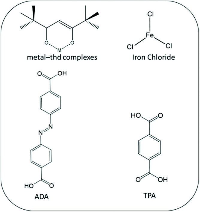 | ||
| Fig. 1 Molecular structures of present precursors. | ||
Film thicknesses were determined from X-ray reflectivity (XRR; PANalytical X'Pert PRO Alfa 1) data fitted by the X'Pert Reflectivity software by PANalytical; the thickness value was further divided by the number of deposition cycles to obtain the so-called growth-per-cycle (GPC) value. Film densities were calculated from the XRR patterns based on the dependency of critical angle θc and mean electron density ρe of the film material, namely, ρe = (θc2π)/(λ2re), where λ is the X-ray wavelength and re is the classical electron radius. The crystallinity of the films was investigated by grazing-incidence X-ray diffraction (GIXRD; PANalytical X'Pert PRO Alfa 1; Cu Kα radiation; incident angle 0.5°).
The surface morphology of the films was studied with scanning electron microscopy (SEM; Hitachi S-4700). The sample specimen was prepared by sputtering an Au–Pd mixture on top of it and analyzing it at a voltage of 10 kV and a current of 15 μA. For elemental analysis, the energy dispersive X-ray spectra (EDX; Tescan Mira3) were recorded at a voltage of 2 kV, operating on a Noran System Six (NSS) software.
For the chemical composition, the films were analyzed with Fourier transform infrared (FTIR; Bruker Alpha II) spectroscopy. The measurements were carried out in a transmission mode in the range of 400–4000 cm−1 with a resolution of 4 cm−1; each given spectrum is an average of 24 measured spectra, from which a spectrum of blank Si is subtracted.
The UV-vis absorbance spectra were recorded for the samples (grown on quartz substrates) in the wavelength range of 200–600 nm (Shimadzu UV-2600 spectrometer). Photoisomerization experiments were carried out under irradiation by UV light (365 nm) using a 200 W xenon-doped mercury lamp (Hamamatsu Lightningcure LC8; cut-off filter for λ = 300–480 nm). At the working distance of 10 mm, the photon flux was 3000 mW cm−2.
Results and discussion
M-ADA (M = Li, Ca, Fe) films
Among the three M-ADA (M = Li, Ca, Fe) materials investigated, the basic ALD/MLD processes were already reported for Fe-ADA and Li-ADA in our earlier works.23,24 For the present work, we elaborated these processes further, and developed an entirely new ALD/MLD process for Ca-ADA. As an exemplary case, we in the following discuss the process parameter optimization for the Ca(thd)2 + ADA process. It should be noted that the growth characteristics including the growth rates were found to be very similar for the two thd-based processes, Ca(thd)2 + ADA and Li(thd)2 + ADA. All the three processes, however, yielded high-quality, homogeneous, and air-stable thin films.In Fig. 2, the deposition parameter optimization for the Ca(thd)2 + ADA process is presented. First, we searched for the optimal temperature range for the depositions using the following ALD/MLD cycle: 5 s Ca(thd)2 pulse → 5 s N2 purge → 10 s ADA pulse → 30 s N2 purge. In Fig. 2(a), the resultant GPC value is plotted against the deposition temperature. Within 280–320 °C, the growth rate remains quite high and relatively constant at ca. 3.4 Å/cycle, after which it starts to decline to ca. 1.5 Å/cycle at 360 °C.
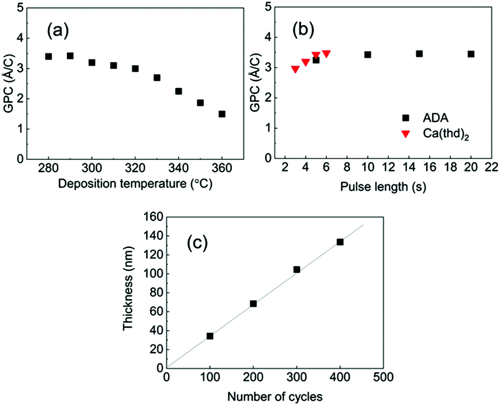 | ||
| Fig. 2 ALD/MLD parameters for the Ca(thd)2 + ADA process: GPC versus (a) deposition temperature and (b) precursor pulse lengths and (c) film thickness versus number of ALD/MLD cycles; in (a) and (b) 200 ALD/MLD cycles; in (b) and (c) deposition temperature 290 °C; in (a)&(c) pulse/purge sequence: Ca(thd)2 5 s, N2 5 s, ADA 10 s, and N2 30 s. | ||
In the next step, we confirmed the fulfillment of the surface saturation criterion for both precursors by gradually increasing the pulse length of one of the precursors at a time while keeping the pulse length for the other precursor fixed, and then monitoring the changes in the GPC value accordingly; these experiments were performed at 290 °C. On the basis of Fig. 2(b), the surface reactions reach saturation in 5 s for Ca(thd)2 and in 10 s for ADA. Thus, we fixed the pulse/purge lengths as follows: 5 s/5 s for Ca(thd)2/N2 and 10 s/30 s for ADA/N2. Finally, we confirmed that the process exhibits linear dependency of the film thickness on the number of deposition cycles, as expected for an ideal ALD/MLD process (Fig. 2(c)).
Based on the ALD/MLD process parameter optimizations, we grew the M-ADA films for the rest of the experiments as follows: Li-ADA films at 270 °C with GPC = 7.0 Å/cycle, Ca-ADA films at 290 °C with GPC = 3.4 Å/cycle, and Fe-ADA films at 280 °C with GPC = 25 Å/cycle. The lower GPC values for the Ca(thd)2 + ADA and Li(thd)2 + ADA processes compared to the FeCl3 + ADA process can be at least partly explained by the steric hindrance of the large-sized thd ligands. All the three processes yielded highly crystalline films; GIXRD patterns are shown in Fig. 3(a). Among the three M-ADA materials, only Li-ADA has been previously synthesized in bulk form.25 However, while the XRD pattern was given for these bulk samples, the crystal structure remained unsolved. Since the crystal structures are unknown, we can only visually compare the GIXRD patterns in Fig. 3(a); tentatively, we conclude that the three crystal structures seem to be different. This is rather understandable as the oxidation states of the metals are different, i.e. Li+, Ca2+, and Fe3+. Even though the crystal structures could not be determined, we could determine the density values for the three M-ADA films from the XRR data; interestingly, the increase in density, i.e. Li-ADA 1.40, Ca-ADA 1.45, and Fe-ADA 1.50 (in g cm−3), follows the expected trend taking into account the metal atom masses and ion sizes.
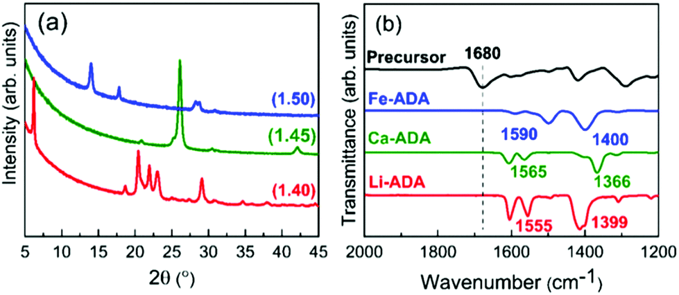 | ||
| Fig. 3 (a) GIXRD patterns and (b) FTIR spectra for M-ADA (M = Li, Ca, Fe) films; numbers in parentheses in (a) are density values. | ||
We could also investigate the bonding structures using FTIR spectroscopy, see Fig. 3(b). Firstly, for all the three M-ADA films, the region of 1700 cm−1 is featureless; this confirms that the ligands of the metal precursors are completely dispatched and the free COOH groups have reacted upon the film growth to form the carboxylate–metal bonds. In all the spectra, the dominant absorption bands are seen around 1400 and 1600 cm−1, arising from the asymmetric (νas) and symmetric (νs) COO− stretchings, respectively. The sharpness of these carboxylate bands is an indication of the crystallinity of the films. Most importantly, the distance (Δ) between the two COO– bands falls between 130 < Δ < 200 cm−1 for all the three films, suggesting that the bonding is of the bridging type.26
In our previous work, we used X-ray photoelectron spectroscopy (XPS) to verify the trivalent oxidation state of iron in the Fe-ADA films.23 The XPS data also confirmed the presence of all the intended elements (Fe, C, O, and N) and revealed the N![[thin space (1/6-em)]](https://www.rsc.org/images/entities/char_2009.gif) :Fe ratio at ca. 2.6. Taking the bridging-type bonding into account, this ratio suggests that the coordination number of iron is five or six. In the present study, we used SEM-EDX to confirm the presence of all the intended elements in our three M-ADA films (Fig. 4). The top-view SEM images in Fig. 4 indicate the largest grains for Li-ADA.
:Fe ratio at ca. 2.6. Taking the bridging-type bonding into account, this ratio suggests that the coordination number of iron is five or six. In the present study, we used SEM-EDX to confirm the presence of all the intended elements in our three M-ADA films (Fig. 4). The top-view SEM images in Fig. 4 indicate the largest grains for Li-ADA.
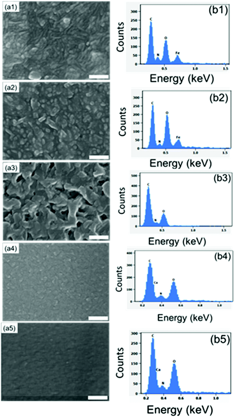 | ||
| Fig. 4 Top-view SEM images of (a1) Fe-ADA, (a2) Fe-ADA–Fe-TPA, (a3) Li-ADA, (a4) Ca-ADA, and (a5) Ca-ADA@Ca-TPA; the scale bar is 200 nm in each image. The corresponding EDX pattern is given in section b. | ||
The UV-vis absorption spectra are depicted in Fig. 5, both for the as-deposited Li-ADA, Ca-ADA, and Fe-ADA films and for the same films taken after being irradiated with UV light (365 nm) for specific time intervals; note that the data for Fe-ADA are replotted from our previous work.23 The strong absorption band due to the π–π* transition of the azobenzene trans isomer27–29 is seen for the as-deposited films at 310, 320, and 333 nm for M = Li, Ca and Fe, respectively. The cis isomer exhibits a weak (forbidden) n–π* band at 400–550 nm;30 this is naturally absent for the as-deposited films.
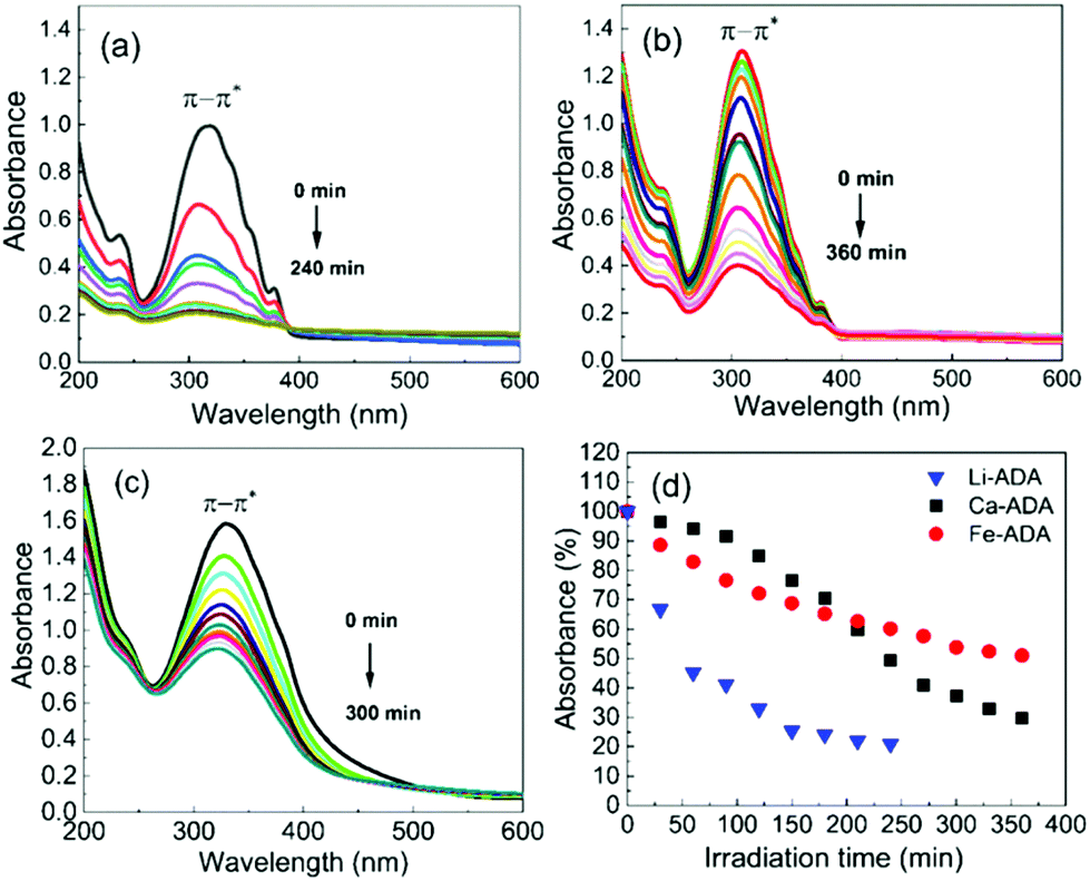 | ||
| Fig. 5 UV-vis spectra for (a) Li-ADA, (b) Ca-ADA, and (c) Fe-ADA films after UV (365 nm) irradiation for different time periods in intervals of 30 min; (d) photoisomerization rate comparison. | ||
Then, upon irradiating the samples with UV light for longer time periods, the trans-to-cis photoisomerization gradually occurs for all the three M-ADA films, seen as a gradual intensity loss of the π–π* band around 310–330 nm. Also seen is a slight blue shift of the peak position and also a tiny intensity gain around 400–550 nm as a fingerprint of the cis form (n–π*). The trans π–π* band nearly disappears for all the samples after sufficient irradiation time, indicating an almost complete trans-to-cis isomerization.27,31 From Fig. 5(d), this reaction occurs fastest for Li-ADA. For bulk M-AZO samples in literature, only in rare cases the trans-to-cis transition is realized to this extent, and if the transition is realized it is typically accompanied by a massive destruction of the crystal lattice.13 We systematically recorded GIXRD patterns and FTIR spectra for our irradiated M-AZO films (Fig. 6). Surprisingly, even though the degree of crystallinity is clearly lowered, our thin films are still crystalline after an irradiation period of 120 min.
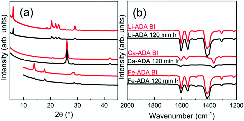 | ||
| Fig. 6 (a) GIXRD and (b) FTIR patterns for Li-ADA, Ca-ADA, and Fe-ADA films before and after UV irradiation for 120 min. | ||
Fe-ADA–Fe-TPA superstructures
To investigate whether we could ease the photoisomerization reaction by diluting the concentration of the photoactive ADA moieties in the lattice, we deposited the Fe-ADA–Fe-TPA films by mixing the FeCl3 + ADA and FeCl3 + TPA23,32 deposition cycles on a 1:1 basis (at the deposition temperature 280 °C). This was done with the anticipation that the crystal lattice could more easily accommodate the strain caused by the trans–cis transformation. In Fig. 7, we display the GIXRD patterns and FTIR spectra for these Fe-ADA–Fe-TPA films together with the patterns recorded for Fe-TPA and Fe-ADA for comparison. Firstly, the mixed Fe-ADA–Fe-TPA films are crystalline as well. Secondly, the diffraction pattern shows several common features with those of Fe-ADA and Fe-TPA but it is not identical to either one. Most importantly, an additional low-angle peak appears at the d-value of ca. 8.7 Å. Hence it seems that the ADA and TPA linkers are organized into a kind of superstructure. We also determined the densities for all the three thin films from their XRR data; as expected, the density (in g cm−3) of the Fe-ADA–Fe-TPA film (1.30) is between those of Fe-ADA (1.50) and Fe-TPA (1.17). Moreover, from the EDX data shown in Fig. 4, it is seen that upon TPA-dilution, the N:Fe ratio decreases as expected. Finally, FTIR analysis revealed both Fe-ADA and Fe-TPA types of bonding features for the Fe-ADA–Fe-TPA film; from Fig. 7(b), the two sets of νs and νas carboxylate peaks are seen at 1395 and 1591 cm−1 (Δ = 196 cm−1; bridging-type binding) like in Fe-ADA and at 1395 and 1503 cm−1 (Δ = 110 cm−1; bidentate binding) like in Fe-TPA.32
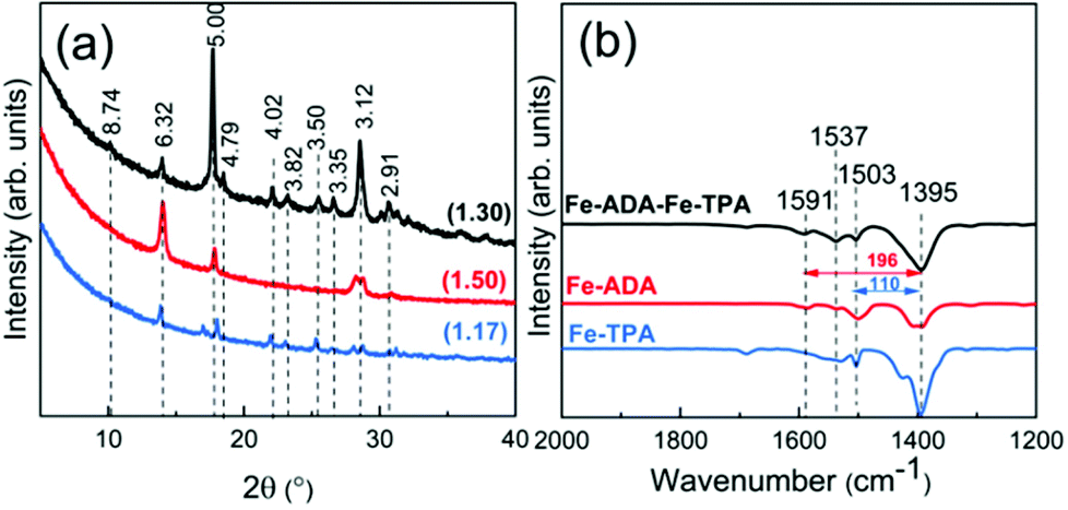 | ||
| Fig. 7 (a) GIXRD patterns and (b) FTIR spectra of Fe-TPA, Fe-ADA, and Fe-ADA–Fe-TPA; numbers in parentheses in (a) are density values and the peak positions are indicated with the d-values (in Å). | ||
The UV-vis absorption spectra for the Fe-ADA–Fe-TPA film (before and after irradiation) are shown in Fig. 8(a). In addition to the AZO-trans π–π* absorption peak at 322 nm, the characteristic 245 nm peak of the TPA linker is also seen.33 Upon UV (365 nm) irradiation, the intensity of the AZO-trans π–π* absorption peak gradually decreases, indicating the progress of the trans–cis photoisomerization reaction. From Fig. 8(b), we can see that the isomerization kinetics are essentially of the same level for the Fe-ADA–Fe-TPA and Fe-ADA films. At the same time, we can see from the GIXRD patterns (Fig. 8(c)) and FTIR spectra (Fig. 8(d)) recorded for the irradiated Fe-ADA–Fe-TPA film in intervals of 15 min that the crystal/bonding structure is nearly perfectly preserved. Hence, we can conclude that the presence of a secondary non-photoresponsive linker may indeed help us to realize the trans–cis photoisomerization of the ADA linker without destroying the crystal lattice.
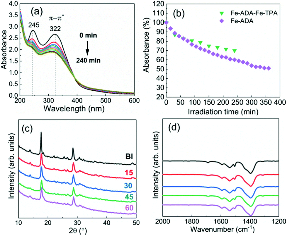 | ||
| Fig. 8 (a) UV-vis spectra for Fe-ADA–Fe-TPA film after UV irradiation for different time periods in intervals of 30 min; (b) photoisomerization rate comparison; (c) GIXRD patterns, and (d) FTIR spectra for Fe-ADA–Fe-TPA film after UV irradiation for different time periods in intervals of 15 min. | ||
Ca-ADA@Ca-TPA films
Finally, we investigated the possibility of depositing crystalline MOF-on-MOF-type films by ALD/MLD. For these experiments, we selected the Ca-ADA@Ca-TPA system, since (i) the ALD/MLD process for in situ crystalline Ca-TPA thin films was known from our previous work34 and (ii) the crystal structure of Ca-TPA was known from bulk samples.35 From Fig. 9(a) and (b), we can see that the GIXRD pattern and FTIR spectrum for our as-deposited Ca-ADA@Ca-TPA film superimpose – as expected – those of Ca-TPA and Ca-ADA shown for comparison. Most interestingly, the GIXRD peaks are most intense and the FTIR features are sharpest for the Ca-ADA@Ca-TPA film, indicating that Ca-ADA crystallizes more perfectly when it is grown on top of crystalline Ca-TPA surface (compared to the Si or glass substrate surfaces). Then, Fig. 9(c) and (d) illustrate the photoisomerization behaviour of the Ca-ADA@Ca-TPA film; compared to the plain Ca-ADA film, the more crystalline Ca-ADA@Ca-TPA film shows even somewhat faster photoisomerization reaction. | ||
| Fig. 9 (a) GIXRD patterns, and (b) FTIR spectra for Ca-ADA@Ca-TPA, Ca-TPA and Ca-ADA films; (c) UV-vis spectra for Ca-ADA@Ca-TPA film after UV irradiation for different time periods in intervals of 30 min; (d) photoisomerization rate comparison. | ||
Conclusions
In the first part of this study, we successfully expanded our pioneering ALD/MLD work on photoresponsive Fe-ADA thin films to Ca-ADA and Li-ADA films. While the Fe-ADA films were grown using FeCl3 as the metal precursor, in the present Ca-ADA and Li-ADA processes we utilized much bulkier Ca(thd)2 and Li(thd) precursors. This naturally resulted in considerably lower growth rates; nevertheless, the films grew in situ crystalline. Tentatively, we concluded that all the three M-AZO (M = Fe, Ca, Li) materials have different (unknown) crystal structures, a fact that is well explained by the different valence states and apparently also different coordination numbers of the three metal constituents. Most importantly, despite the different crystal structures, we could demonstrate the trans–cis photoisomerization of the AZO moieties for the Li-ADA and Ca-ADA films as well.In the second part of this study, we challenged for the first time the possibility to deposit different types of mixed metal–organic structures by ALD/MLD. For the Ca-ADA@Ca-TPA films, we could show that the underlining Ca-TPA film improved the crystallinity of the Ca-ADA film grown on top of it. Most importantly, we were also able to grow Fe-ADA–Fe-TPA superstructured films with a 1:1 frequency of the Fe-ADA and Fe-TPA cycles applied. For these thin films, improved crystallinity retention upon the photoisomerization reaction was demonstrated, which was attributed to the successful dilution of the photoactive ADA linkers with the non-active TPA linkers.
Accordingly, our work has represented several new strategies to exploit the ALD/MLD technique in synthesizing exciting new metal–organic crystals with novel/complex compositions and enhanced functionalities.
Conflicts of interest
There are no conflicts to declare.Acknowledgements
We acknowledge the funding from the European Research Council under the European Union's Seventh Framework Programme (FP/2007-2013)/ERC Advanced Grant Agreement (339478) and the Academy of Finland (296299) and the use of the RawMatters Finland Infrastructure (RAMI) at Aalto University.Notes and references
- O. M. Yaghi and H. Li, J. Am. Chem. Soc., 1995, 117, 10401–10402 CrossRef CAS.
- H. Furukawa, K. E. Cordova, M. O'Keeffe and O. M. Yaghi, Science, 2013, 341, 1230444 CrossRef.
- S. Furukawa, K. Hirai, Y. Takashima, K. Nakagawa, M. Kondo, T. Tsuruoka, O. Sakata and S. Kitagawa, Chem. Commun., 2009, 5097–5099 RSC.
- O. Shekhah, K. Hirai, H. Wang, H. Uehara, M. Kondo, S. Diring, D. Zacher, R. A. Fischer, O. Sakata, S. Kitagawa, S. Furukawa and C. Wöll, Dalton Trans., 2011, 40, 4954–4958 RSC.
- X. Song, M. Oh and M. S. Lah, Inorg. Chem., 2013, 52, 10869–10876 CrossRef CAS.
- Y. Gu, Y. N. Wu, L. Li, W. Chen, F. Li and S. Kitagawa, Angew. Chem., Int. Ed., 2017, 56, 15658–15662 CrossRef CAS.
- D. Kim, G. Lee, S. Oh and M. Oh, Chem. Commun., 2019, 55, 43–46 RSC.
- K. Ikigaki, K. Okada, Y. Tokudome, T. Toyao, P. Falcaro, C. J. Doonan and M. Takahashi, Angew. Chem., Int. Ed., 2019, 5005, 6886–6890 CrossRef.
- X. Yu, Z. Wang, M. Buchholz, N. Füllgrabe, S. Grosjean, F. Bebensee, S. Bräse, C. Wöll and L. Heinke, Phys. Chem. Chem. Phys., 2015, 17, 22721–22725 RSC.
- H. M. D. Bandara and S. C. Burdette, Chem. Soc. Rev., 2012, 41, 1809–1825 RSC.
- S. Castellanos, F. Kapteijn and J. Gascon, CrystEngComm, 2016, 18, 4006–4012 RSC.
- C. L. Jones, A. J. Tansell and T. L. Easun, J. Mater. Chem. A, 2016, 4, 6714–6723 RSC.
- A. M. Rice, C. R. Martin, V. A. Galitskiy, A. A. Berseneva, G. A. Leith and N. B. Shustova, Chem. Rev. DOI:10.1021/acs.chemrev.9b00350.
- E. Ahvenniemi and M. Karppinen, Chem. Commun., 2016, 52, 1139–1142 RSC.
- M. Nisula and M. Karppinen, Nano Lett., 2016, 16, 1276–1281 CrossRef CAS.
- J. Penttinen, M. Nisula and M. Karppinen, Chem. – Eur. J., 2017, 23, 18225–18231 CrossRef CAS.
- J. Heiska, M. Nisula, E.-L. Rautama, A. J. Karttunen and M. Karppinen, Dalton Trans., 2020, 49, 1591–1599 RSC.
- S. M. George, Chem. Rev., 2010, 110, 111–131 CrossRef CAS.
- K. B. Klepper, O. Nilsen and H. Fjellvåg, Dalton Trans., 2010, 39, 11628–11635 RSC.
- K. B. Lausund, V. Petrovic and O. Nilsen, Dalton Trans., 2017, 46, 16983–16992 RSC.
- T. Tynell, I. Terasaki, H. Yamauchi and M. Karppinen, J. Mater. Chem. A, 2013, 1, 13619–13624 RSC.
- F. Krahl, A. Giri, J. A. Tomko, T. Tynell, P. E. Hopkins and M. Karppinen, Adv. Mater. Interfaces, 2018, 5, 1701692 CrossRef.
- A. Khayyami, A. Philip and M. Karppinen, Angew. Chem., Int. Ed., 2019, 131, 13534–13538 CrossRef.
- J. Multia, J. Heiska, A. Khayyami and M. Karppinen, submitted.
- C. Luo, O. Borodin, X. Ji, S. Hou, K. J. Gaskell, X. Fan, J. Chen, T. Deng, R. Wang, J. Jiang and C. Wang, Proc. Natl. Acad. Sci. U. S. A., 2018, 115, 2004–2009 CrossRef CAS.
- K. B. Klepper, O. Nilsen, S. Francis and H. Fjellvåg, Dalton Trans., 2014, 43, 3492–3500 RSC.
- J. Han, D. Yan, W. Shi, J. Ma, H. Yan, M. Wei, D. G. Evans and X. Duan, J. Phys. Chem. B, 2010, 114, 5678–5685 CrossRef CAS.
- A. Wu and D. R. Talham, Langmuir, 2000, 16, 7449–7456 CrossRef CAS.
- W. Q. Fu, M. Liu, Z. G. Gu, S. M. Chen and J. Zhang, Cryst. Growth Des., 2016, 16, 5487–5492 CrossRef CAS.
- A. Modrow, D. Zargarani, R. Herges and N. Stock, Dalton Trans., 2011, 40, 4217–4222 RSC.
- A. Khayyami and M. Karppinen, Chem. Mater., 2018, 30, 5904–5911 CrossRef CAS.
- A. Tanskanen and M. Karppinen, Sci. Rep., 2018, 8, 1–8 CrossRef CAS.
- A. Shafaei, M. Nikazar and M. Arami, Desalination, 2010, 252, 8–16 CrossRef CAS.
- E. Ahvenniemi and M. Karppinen, Chem. Mater., 2016, 28, 6260–6265 CrossRef CAS.
- M. Mazaj, G. Mali, M. Rangus, E. Žunkovič, V. Kaučič and N. Z. Logar, J. Phys. Chem. C, 2013, 117, 7552–7564 CrossRef CAS.
| This journal is © The Royal Society of Chemistry 2020 |