 Open Access Article
Electrocatalytic proton-reduction behaviour of telluride-capped triiron clusters: tuning of overpotentials and stabilization of redox states relative to lighter chalcogenide analogues†
Ahibur
Rahaman
a,
George C.
Lisensky
 *b,
Jess
Browder-Long
b,
David A.
Hrovat
cd,
Michael G.
Richmond
d,
Ebbe
Nordlander
 *a and
Graeme
Hogarth
 *e
*e
aChemical Physics, Department of Chemistry, Lund University, Box 124, SE-221 00 Lund, Sweden. E-mail: Ebbe.Nordlander@chemphys.lu.se
bDepartment of Chemistry, Beloit College, 700 College Street, Beloit, WI 53511, USA
cCenter for Advanced Scientific Computing and Modeling, University of North Texas, Denton, TX 76203, USA
dDepartment of Chemistry, University of North Texas, 1155 Union Circle, Box 305070, Denton, TX 76203, USA
eDepartment of Chemistry, King's College London, Britannia House, 7 Trinity Street, London SE1 1DB, UK. E-mail: graeme.hogarth@kcl.ac.uk
First published on 14th May 2020
Abstract
Reaction of [Fe3(CO)9(μ3-Te)2] (1) with the corresponding phosphine has been used to prepare the phosphine-substituted tellurium-capped triiron clusters [Fe3(CO)9(μ3-Te)2(PPh3)] (2), [Fe3(CO)8(μ3-Te)2(PPh3)] (3) and [Fe3(CO)7(μ3-Te)2(μ-R2PXPR2)] (X = CH2, R = Ph (4), Cy (5); X = NPri, R = Ph (6)). The directly related cluster [Fe3(CO)7(μ3-CO)(μ3-Te)(μ-dppm)] (7) was isolated from the reaction of [Fe3(CO)10(μ-Ph2PCH2PPh2)] with elemental tellurium. The electrochemistry of these new clusters has been probed by cyclic voltammetry, and selected complexes have been tested as proton reduction catalysts. Each 50-electron dicapped cluster exhibits two reductive processes; the first has good chemical reversibility in all cases but the reversibility of the second is dependent upon the nature of the supporting ligands. For the parent cluster 1 and the diphosphine derivatives 4–5 this second reduction is reversible, but for the PPh3 complex 3 it is irreversible, possibly as a result of CO or phosphine loss. The nature of the reduced products of 1 has been probed by DFT calculations. Upon addition of one electron, an elongation of one of the Fe–Te bonding interactions is found, while the addition of the second electron affords an open-shell triplet which is more stable by 8.8 kcal mol−1 than the closed-shell singlet dianion and has two elongated Fe–Te bonds. The phosphine-substituted clusters also exhibit oxidation chemistry but with poor reversibility in all cases. Since the reduction potentials for the tellurium-capped clusters occur at more positive potentials than for the sulfur and selenium analogues, and the redox processes also show better reversibility than for the S/Se analogues, the tellurium-capped clusters 1 and 3–5 have been examined as proton reduction catalysts. In the presence of p-toluenesulfonic acid (TsOH) or trifluoroacetic acid (TFA), these clusters reduce protons to H2 at both their first and second reduction potentials. Electron uptake at the second reduction potential is far greater than the first, suggesting that the open-shell triplet dianions are efficient catalysts. As expected, the catalytic overpotential increases upon successive phosphine substitution but so does the current response. A mechanistic scheme that takes the roles of the supporting ligands on the preferred route(s) to H2 production and release into account is presented.
Introduction
Hydrogenases are enzymes that catalyse the production and oxidation of molecular hydrogen using earth-abundant metals1,2 There are three types of hydrogenases3,4 and all share common features; there is a proton/hydrogen binding site, a redox centre, and π-acceptor (CO and/or CN−) and sulfur ligands capable of stabilising metals in low oxidation states. The most widely studied hydrogenases are the [FeFe]-hydrogenases that contain a diiron centre supported by carbonyl and cyanide ligands and spanned by a dithiolate bridge.5–7 These are extremely efficient catalysts for the reduction of protons to give hydrogen, and a plethora of biomimetics of this active site have been prepared and studied.8–17 Far less studied are biomimetic complexes of [FeNi]-hydrogenases.18–21 These enzymes normally contain sulfur-bound cysteine ligands; however, some variants that are more stable towards oxygen also contain selenium (selenocysteine).18–21In searching for simple, stable and efficient iron-based proton reduction catalysts, we22–24 and others25–31 have turned our attention to chalcogenide-stabilised tri- and tetra-iron carbonyl clusters as potential candidates. These include the disulfide-capped cluster [Fe3(CO)9(μ3-S)2]27,28 together with various diphosphine derivatives.29 We and others32 have investigated the proton-reduction chemistry of a series of sulfur and selenium-containing mono- and dichalcogenide-capped clusters [Fe3(CO)7(μ3-CO)(μ3-E)(μ-dppm)] and [Fe3(CO)7(μ3-E)2(μ-dppm)] (E = S, Se). While these clusters can act as proton-reduction catalysts, their activity is limited by the instability of the anions generated upon reduction, possibly due to carbonyl loss, and the relatively high potentials required for efficient proton reduction.
While sulfur and selenium are widely found in nature, the heavier congener tellurium has no apparent biological function33 although tellurium-containing amino acids can be found in some fungi34 and tellurium compounds have shown anti-cancer activity.35 Tellurium is more metallic in nature than sulfur and selenium, and, consequently, complexes containing tellurium might be expected to be reduced at less negative potentials than analogous sulfur and selenium species, while also generating relatively more stable reduced species. Support for this hypothesis, and partial inspiration for our current work on tellurium-containing iron carbonyl clusters, comes from recent work by Song and co-workers36,37 who showed that for the series [Fe2(CO)6{μ-E(CH2)3E}] (E = S, Se, Te), the tellurium analogue is reduced at less negative potentials than the sulfur or selenium analogues and that the anion generated was also more stable.
The chemistry of low-valent tellurium-containing iron clusters is well-developed and shows a rich and diverse array of cluster core geometries.38–55 A notable feature is their ability to undergo addition reactions with a range of two-electron donor ligands to form adducts with one less iron–iron bond,42–52 which is in marked contrast with most related sulfur and selenium-containing complexes, the related chemistry of which is dominated by substitution resulting from CO loss.43,44 An example of the addition chemistry discussed above are reactions of the 50-electron cluster [Fe3(CO)9(μ3-Te)2] (1) with Lewis bases (L) that result in high yield generation of 52-electron clusters of the type [Fe3(CO)9(L)(μ3-Te)2], containing a single iron–iron bond.43,56 This suggests that the one- and two-electron reduction products of [Fe3(CO)9(μ3-Te)2] (1) and related phosphine derivatives may be particularly stable and provide good access to proton reduction catalysis. Although the electronic structure of 1 is well-known,42–46 the electrochemical and (electro)catalytic properties of 1 remain unexplored, to the best of our knowledge. Herein we report the electrochemical and electrocatalytic reduction of protons to hydrogen by a series of 50-electron telluride-capped clusters, and a comparison of their behaviour with that of related sulfur- and selenium-capped derivatives.27–32
Experimental
General procedures
Unless otherwise stated, purification of solvents, reactions, and manipulation of compounds were carried out under a nitrogen atmosphere using standard Schlenk techniques. Reagent grade solvents were dried by standard procedures and were freshly distilled prior to use. All chromatographic separations and ensuing workup were carried out in air. Thin layer chromatography was carried out on glass plates pre-coated with Merck 60 0.5 mm silica gel. All phosphines were purchased from Acros Organics Chemicals Inc. and used as received. The starting material [Fe3(CO)9(μ3-Te)2] (1) was prepared as previously reported.38 Infrared spectra were recorded on Nicolet 6700 FT-IR or Nicolet Avatar 360 FT-IR spectrometers in solution cells fitted with calcium fluoride or sodium chloride plates; subtraction of the solvent absorptions was achieved by computation. Fast atom bombardment (FAB) mass spectra were obtained on a JEOL SX-102 spectrometer using 3-nitrobenzyl alcohol as matrix and CsI as calibrant. Proton and 31P{1H} NMR spectra were recorded on a Varian Unity 500 MHz or a Bruker AMX400 spectrometer. Chemical shifts were referenced to residual solvent resonances or 85% H3PO4.Synthesis of [Fe3(CO)9(μ3-Te)2(PPh3)] (2) and [Fe3(CO)8(μ3-Te)2(PPh3)] (3)55
A benzene solution (20 mL) of 1 (60 mg, 0.09 mmol) and PPh3 (23 mg, 0.09 mmol) was refluxed for 12 h. The solvent was removed under reduced pressure and the residue was chromatographed by TLC on silica. Elution with n-hexane/CH2Cl2 (3![[thin space (1/6-em)]](https://www.rsc.org/images/entities/char_2009.gif) :
:![[thin space (1/6-em)]](https://www.rsc.org/images/entities/char_2009.gif) 1 v/v) developed two bands. The faster moving band gave [Fe3(CO)8(μ3-Te)2(PPh3)] (3) (28 mg, 34%) as black crystals and the second band afforded [Fe3(CO)9(μ3-Te)2(PPh3)] (2) (24 mg, 23%) as red crystals after recrystallization from hexane/CH2Cl2 at 4 °C. Characterization data for 2: IR (ν(CO), CH2Cl2): 2063w, 2037s, 2012vs, 1972s cm−1. 1H NMR (CDCl3): δ 7.71–7.41 (m, 15 H, Ph). 31P{1H} NMR (CDCl3): δ 46.11 (s). ESI-MS: m/z 936 [M+, calc 937.11]. Characterization data for 3: IR (ν(CO), CH2Cl2): 2053s, 2014vs, 1987s, 1937w cm−1. 1H NMR (CDCl3): δ 7.69–7.42 (m, 15 H, Ph). 31P{1H} NMR (CDCl3): δ 72.1 (s). ESI-MS: m/z 909 [M+, calc 909.10].
1 v/v) developed two bands. The faster moving band gave [Fe3(CO)8(μ3-Te)2(PPh3)] (3) (28 mg, 34%) as black crystals and the second band afforded [Fe3(CO)9(μ3-Te)2(PPh3)] (2) (24 mg, 23%) as red crystals after recrystallization from hexane/CH2Cl2 at 4 °C. Characterization data for 2: IR (ν(CO), CH2Cl2): 2063w, 2037s, 2012vs, 1972s cm−1. 1H NMR (CDCl3): δ 7.71–7.41 (m, 15 H, Ph). 31P{1H} NMR (CDCl3): δ 46.11 (s). ESI-MS: m/z 936 [M+, calc 937.11]. Characterization data for 3: IR (ν(CO), CH2Cl2): 2053s, 2014vs, 1987s, 1937w cm−1. 1H NMR (CDCl3): δ 7.69–7.42 (m, 15 H, Ph). 31P{1H} NMR (CDCl3): δ 72.1 (s). ESI-MS: m/z 909 [M+, calc 909.10].
Synthesis of [Fe3(CO)7(μ3-Te)2(μ-dppm)] (4)
A benzene solution (30 mL) of 1 (100 mg, 0.15 mmol) and dppm (Ph2PCH2PPh2, 57 mg, 0.15 mmol) was refluxed for 30 min. The solvent was removed under reduced pressure, and the residue was chromatographed by TLC on silica. Elution with n-hexane/CH2Cl2 (9![[thin space (1/6-em)]](https://www.rsc.org/images/entities/char_2009.gif) :
:![[thin space (1/6-em)]](https://www.rsc.org/images/entities/char_2009.gif) 1 v/v) developed one band which gave [Fe3(CO)7(μ3-Te)2(μ-dppm)] (4) (65 mg, 44%) as black crystals after recrystallization from hexane/CH2Cl2 at 4 °C. Spectral data for 4: IR (ν(CO), cyclohexane): 2040s, 1984vs, 1961w, 1942w, 1936w cm−1. 1H NMR (CDCl3): δ 7.80–7.09 (m, 20 H, Ph), 4.16 (m, 2H, CH2). 31P{1H} NMR (CDCl3): δ 51.0 (d, J 62 Hz), 45.5 (d, J 62 Hz). ESI-MS: m/z 1003 [M+, calc 1003.19].
1 v/v) developed one band which gave [Fe3(CO)7(μ3-Te)2(μ-dppm)] (4) (65 mg, 44%) as black crystals after recrystallization from hexane/CH2Cl2 at 4 °C. Spectral data for 4: IR (ν(CO), cyclohexane): 2040s, 1984vs, 1961w, 1942w, 1936w cm−1. 1H NMR (CDCl3): δ 7.80–7.09 (m, 20 H, Ph), 4.16 (m, 2H, CH2). 31P{1H} NMR (CDCl3): δ 51.0 (d, J 62 Hz), 45.5 (d, J 62 Hz). ESI-MS: m/z 1003 [M+, calc 1003.19].
Synthesis of [Fe3(CO)7(μ3-Te)2(μ-dcpm)] (5)
A benzene solution (30 mL) of 1 (92 mg, 0.14 mmol) and bis(dicyclohexylphosphino)methane (dcpm) (55 mg, 0.14 mmol) was refluxed for 25 min. The solvent was removed under reduced pressure, and the residue was chromatographed by TLC on silica. Elution with n-hexane/CH2Cl2 (4![[thin space (1/6-em)]](https://www.rsc.org/images/entities/char_2009.gif) :
:![[thin space (1/6-em)]](https://www.rsc.org/images/entities/char_2009.gif) 1 v/v) developed two bands. The faster-moving band gave unreacted (1) and the second band afforded [Fe3(CO)7(μ3-Te)2(μ-dcpm)] (5) (15 mg, 11%) as black crystals after recrystallization from hexane/CH2Cl2 at 4 °C. Spectral data for 5: IR (ν(CO): 2035s, 1968vs, 1940 m, 1915w cm−1. 1H NMR (CDCl3): δ 2.80 (br, 2 H, CH2), 2.28–1.79 (m, 44 H, Cy). 31P{1H} NMR (CDCl3): δ 64.7 (d, J 42 Hz), 51.7 (d, J 42 Hz). HRMS: m/z (ESI−): 1062.8556 [M + Cl−, calc. 1062.8547].
1 v/v) developed two bands. The faster-moving band gave unreacted (1) and the second band afforded [Fe3(CO)7(μ3-Te)2(μ-dcpm)] (5) (15 mg, 11%) as black crystals after recrystallization from hexane/CH2Cl2 at 4 °C. Spectral data for 5: IR (ν(CO): 2035s, 1968vs, 1940 m, 1915w cm−1. 1H NMR (CDCl3): δ 2.80 (br, 2 H, CH2), 2.28–1.79 (m, 44 H, Cy). 31P{1H} NMR (CDCl3): δ 64.7 (d, J 42 Hz), 51.7 (d, J 42 Hz). HRMS: m/z (ESI−): 1062.8556 [M + Cl−, calc. 1062.8547].
Synthesis of [Fe3(CO)7(μ3-Te)2(μ-dppa)] (6)
A benzene solution (20 mL) of 1 (50 mg, 0.074 mmol) and bis(diphenylphosphino)iso-propylamine (dppa) (55 mg, 0.074 mmol) was refluxed for 1.5 h. The solvent was removed under reduced pressure and the residue was chromatographed by TLC on silica. Elution with n-hexane/CH2Cl2 (4![[thin space (1/6-em)]](https://www.rsc.org/images/entities/char_2009.gif) :
:![[thin space (1/6-em)]](https://www.rsc.org/images/entities/char_2009.gif) 1 v/v) developed two bands. The faster moving band gave unreacted 1 and the second band afforded [Fe3(CO)7(μ3-Te)2(μ-dppa)] (6) (7 mg, 9%) as black crystals after recrystallization from hexane/CH2Cl2 at 4 °C. Spectral data for 6: IR (ν(CO): 2036s, 1974vs, 1924w cm−1. 1H NMR (CDCl3): δ 7.93–7.44 (m, 20H, Ph), 3.89–3.65 (m, 1H), 1.27 (m, 3H), 0.86 (m, 3H). 31P{1H} NMR (CDCl3): δ 126.4 (d, J 78.1 Hz), 109.1 (d, J 78.1 Hz). HRMS: m/z (ESI−): 1081.7101 [M + Cl−, calc. 1081.7091].
1 v/v) developed two bands. The faster moving band gave unreacted 1 and the second band afforded [Fe3(CO)7(μ3-Te)2(μ-dppa)] (6) (7 mg, 9%) as black crystals after recrystallization from hexane/CH2Cl2 at 4 °C. Spectral data for 6: IR (ν(CO): 2036s, 1974vs, 1924w cm−1. 1H NMR (CDCl3): δ 7.93–7.44 (m, 20H, Ph), 3.89–3.65 (m, 1H), 1.27 (m, 3H), 0.86 (m, 3H). 31P{1H} NMR (CDCl3): δ 126.4 (d, J 78.1 Hz), 109.1 (d, J 78.1 Hz). HRMS: m/z (ESI−): 1081.7101 [M + Cl−, calc. 1081.7091].
Synthesis of [Fe3(CO)7(μ3-Te)2(μ-dppm)] (4) and [Fe3(CO)7(μ3-CO)(μ3-Te)(μ-dppm)] (7)
A CH2Cl2 solution (20 mL) of 1 (40 mg, 0.048 mmol) and elemental tellurium (12.3 mg, 0.096 mmol) was refluxed for 24 h. The solvent was removed under reduced pressure, and the residue was chromatographed by TLC on silica gel. Elution with cyclohexane/CH2Cl2 (9![[thin space (1/6-em)]](https://www.rsc.org/images/entities/char_2009.gif) :
:![[thin space (1/6-em)]](https://www.rsc.org/images/entities/char_2009.gif) 1 v/v) developed three bands. The faster moving band gave the known cluster [Fe3(CO)7(μ3-Te)2(μ-dppm)] (4) (4 mg, 7%),18 the second band gave unreacted 1 and the third band afforded [Fe3(CO)7(μ3-CO)(μ3-Te)(μ-dppm)] (7) (5 mg, 11%) as red crystals after recrystallization from hexane/CH2Cl2 at 4 °C. Spectral data for 7: IR (ν(CO), CH2Cl2): 2031s, 1983s, 1965vs, 1715w cm−1. 1H NMR (CDCl3): δ 7.77–7.29 (m, 20H, Ph), 2.95–2.91 (m, H), 2.89–2.86 (m, H). 31P{1H} NMR (CDCl3): δ 55.1 (s). ESI-MS: m/z 1030 [M+, calc 1031.20].
1 v/v) developed three bands. The faster moving band gave the known cluster [Fe3(CO)7(μ3-Te)2(μ-dppm)] (4) (4 mg, 7%),18 the second band gave unreacted 1 and the third band afforded [Fe3(CO)7(μ3-CO)(μ3-Te)(μ-dppm)] (7) (5 mg, 11%) as red crystals after recrystallization from hexane/CH2Cl2 at 4 °C. Spectral data for 7: IR (ν(CO), CH2Cl2): 2031s, 1983s, 1965vs, 1715w cm−1. 1H NMR (CDCl3): δ 7.77–7.29 (m, 20H, Ph), 2.95–2.91 (m, H), 2.89–2.86 (m, H). 31P{1H} NMR (CDCl3): δ 55.1 (s). ESI-MS: m/z 1030 [M+, calc 1031.20].
Electrochemistry
Electrochemistry was carried out under solvent-saturated nitrogen in deoxygenated CH2Cl2 and MeCN solutions with 0.1 M [NBu4][PF6] as the supporting electrolyte. The working electrode was a 2 mm diameter glassy carbon electrode (GCE) that was polished with a 0.3 μm alumina slurry as needed, the counter electrode was a platinum wire, and the Ag/AgCl reference electrode was separated from the working electrode by a glass frit. Ferrocene was added as an internal standard57 and potentials are referenced versus the ferrocenium/ferrocene couple (Fc+/Fc). For the electrocatalytic studies, the catalyst (cluster) concentrations were 1 mM. A Pine Wave Now potentiostat was used for all electrochemical measurements. Catalysis studies were carried out by adding known equivalents of p-toluenesulfonic acid (TsOH) or trifluoroacetic acid (TFA) (Sigma-Aldrich).Computational methodology
All calculations were performed with the hybrid DFT functional B3LYP, as implemented by the Gaussian 09 program package.58 This functional utilizes the Becke three-parameter exchange functional (B3),59 combined with the correlation functional of Lee, Yang and Parr (LYP).60 The iron atoms were described by Stuttgart–Dresden effective core potentials (ecp) and an SDD basis set, while the 6-31+G(d′) basis set was employed for the remaining atoms. The reported geometries were fully optimized, and the analytical second derivatives were evaluated and found to possess only positive eigenvalues. The geometry-optimized structures have been drawn with the JIMP2 molecular visualization and manipulation program.61,62Results and discussion
Synthesis and characterisation
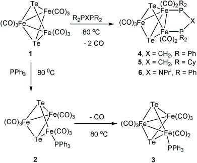
The parent cluster [Fe3(CO)9(μ3-Te)2] (1) was synthesized by a literature procedure38 from Fe(CO)5 and K2TeO3, and the phosphine derivatives were prepared as shown in Scheme 1. Treatment of 1 with PPh3 in benzene at 80 °C for 12 h afforded a mixture of the addition product [Fe3(CO)9(μ3-Te)2(PPh3)] (2) and the mono-substituted cluster [Fe3(CO)8(μ3-Te)2(PPh3)] (3). The dppm complex, [Fe3(CO)7(μ3-Te)2(μ-dppm)] (4), was prepared according to the method of Rauchfuss.43 This reaction also proceeds via initial phosphine addition43 and CO loss,47 but the intermediate nona- and octa-carbonyl complexes were not isolated. The bis(dicyclohexylphosphino)methane (dcpm) and bis(diphenylphosphino)iso-propylamine (dppa) derivatives, [Fe3(CO)7(μ3-Te)2(μ-dcpm)] (5) and [Fe3(CO)7(μ3-Te)2(μ-dppa)] (6), have not been reported previously. Both 5 and 6 were formed in low yields but gave sufficient amounts for full characterisation. The 31P{1H} NMR spectra of 4–6 each displayed a pair of doublets at 51.0 and 45.5 ppm (d, J = 62 Hz) for 4, 64.7 and 51.6 ppm (d, J = 42 Hz) for 5, 126.4 and 109.1 ppm (d, J = 78.1 Hz) for 6, showing that the diphosphine bridges across a metal–metal bond leading to chemical and magnetic inequivalence of the two phosphorus centres.43,47 It may be noted that the sulfur and selenium analogues of 4 are known.63–65 For both the S and Se analogues of 4, two isomers are detected – one symmetric with the dppm ligand bridging the two irons that are not directly bonded to each other, and a second asymmetric isomer corresponding to the structure of 4 (Scheme 1). No symmetric isomer of 4 was detected in the present work. This is in agreement with the observation that the analogous reaction of [Fe3(CO)9(μ3-S)2] with dppm produces the asymmetric isomer of [Fe3(CO)7(μ3-S)2(μ-dppm)] exclusively.63 While solutions of both 4 and 5 are stable in air, this is not the case for 6, which oxidises rapidly to generate a species tentatively assigned as [Fe3(CO)8(μ3-Te)2(μ-dppa)]+ on the basis of related work we have recently carried out.56Heating [Fe3(CO)10(μ-dppm)] with tellurium at 40 °C for one day led to the isolation of small amounts of 4 and the mono-capped cluster [Fe3(CO)7(μ3-CO)(μ3-Te)(μ-dppm)] (7) (Scheme 2). Spectroscopic data for the latter are very similar to that for the sulfur and selenium analogues;32 most notably the triply bridging carbonyl ligand appears at 1715 cm−1 in the IR spectrum while the 31P{1H} NMR spectrum contains only a singlet at δ 55.1. Interestingly, while both [Fe3(CO)9(μ3-CO)(μ3-S)]66 and [Fe3(CO)9(μ3-CO)(μ3-Se)]67 have been reported previously, the parent tellurium-capped cluster [Fe3(CO)9(μ3-CO)(μ3-Te)] remains unknown. Due to the small amounts of 7 generated no further studies were carried out; current efforts are focused on improving the yield of this cluster.
Electrochemical studies
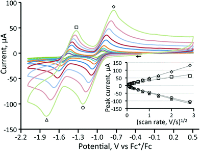
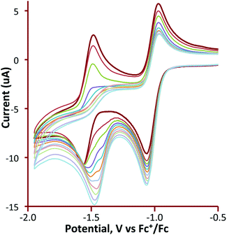
Cyclic voltammetry of 1 and 3–5 was investigated in CH2Cl2 under a nitrogen atmosphere, and important features are summarized in Table 1. The cluster [Fe3(CO)9(μ3-Te)2] (1) shows two chemically reversible one-electron reduction processes at −0.97 V (ΔE = 155 mV) and −1.51 V (ΔE = 145 mV) (Fig. 1). These are at significantly less negative potentials than those found for [Fe3(CO)9(μ3-S)2] (−1.03 and −1.75 V)27 and [Fe3(CO)9(μ3-Se)2] (−1.03 and −1.68 V)32 in CH2Cl2. Similar behaviour has been noted in the [Fe2(CO)6{μ-E(CH2)3E}] (E = S, Se, Te) series of diiron complexes,36,37,68,69 where the first reduction potential of the tellurium derivative (at −1.58 V) was 0.03 and 0.09 V more positive than for the selenium and sulfur derivatives, respectively. A further difference between 1 and its sulfur and selenium analogues relates to the (chemical) reversibility of the reduction processes. For 1, two sharp reduction peaks are observed between scan rates of 0.01–8 V s−1 although at scan rates of 1 V s−1 and greater the peak height for the reverse of the second reduction is less than expected. For both the sulfide and selenide complexes, the first reduction potential is reversible but the second reduction displays far less reversibility. The shift of the reductions to more positive potentials and the greater chemical reversibility of the reductive processes are encouraging signs for the use of 1 and related phosphine derivatives as proton reduction catalysts and suggest that the larger tellurium with its more metallic character is capable of stabilising these clusters in a wide range of redox states.| Complex | Potential (E1/2) of first reduction (V) | Potential (E1/2) of second reduction (V) |
|---|---|---|
| [Fe3(CO)9(μ3-Te)2] (1) | −0.97 (ΔE = 155 mV) | −1.51 (ΔE = 145 mV) |
| [Fe3(CO)8(μ3-Te)2(PPh3)] (3) | −1.24 (ΔE = 190 mV) | −1.91 (ΔE = 270 mV) |
| [Fe3(CO)7(μ3-Te)2(μ-dppm)] (4) | −1.37 (ΔE = 110 mV) | −1.77 (ΔE = 110 mV) |
| [Fe3(CO)7(μ3-Te)2(μ-dcpm)] (5) | −1.51 (ΔE = 131 mV) | −1.84 (ΔE = 145 mV) |
| [Fe3(CO)9(μ3-S)2]27 | −1.03 | −1.75 |
| [Fe3(CO)9(μ3-Se)2]32 | −1.03 (ΔE = 330 mV) | −1.68 (ΔE = 350 mV) |
| [Fe3(CO)7(μ3-S)2(μ-dppm)]32 | −1.55 (ΔE = 215 mV) | |
| [Fe3(CO)7(μ3-Se)2(μ-dppm)]32 | −1.45 (ΔE = 165 mV) | −2.05 (ΔE = 235 mV) |
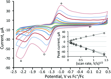
We have also investigated the electrochemistry of [Fe3(CO)8(μ3-Te)2(PPh3)] (3) and the three diphosphine derivatives [Fe3(CO)7(μ3-Te)2(μ-R2PXPR2)] (4–6). Substitution of a carbonyl ligand in 1 for PPh3 predictably resulted in a shift of the reduction potentials of [Fe3(CO)8(μ3-Te)2(PPh3)] (3) to more negative potentials (Table 1) while the second reduction becomes completely irreversible (Fig. 2). This suggests that upon the second reduction either a carbonyl or the phosphine is lost, resulting in chemical irreversibility. Carbonyl loss has been proposed to occur at the second reduction potential of [Fe3(CO)9(μ3-S)2].32
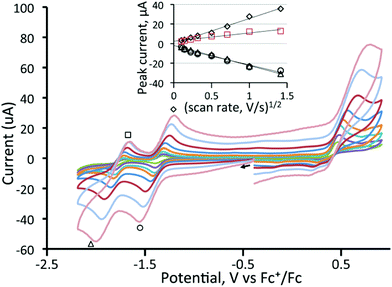
In contrast to the behaviour found for 3, CVs of all three diphosphine-bridged complexes [Fe3(CO)7(μ3-Te)2(μ-R2PXPR2)] (4–6) show two chemically reversible or quasi-reversible reduction peaks, akin to those seen for 1. All are summarised in Table 1, and data for the dppm and dcpm derivatives 4 and 5 are shown in Fig. 3 and 4, respectively. The dppa derivative 6 shows quite different behaviour as seen in Fig. S1 (ESI†), with both reductive processes being irreversible; this complex will not be discussed further. As expected, removal of a further carbonyl ligand and addition of an electron-releasing phosphine leads to a shift to more negative reduction potentials with respect to those in 1. The dppm complex 4 (Fig. 3) shows two reversible reduction waves at −1.37 V and −1.77 V, which are shifted to −1.28 and −1.70 V in MeCN (Fig. S2†), while for the more electron-releasing dcpm complex 5 these waves are seen at −1.51 V and −1.84 V. The reversibility of these waves provides strong evidence that the Fe3Te2P2 core remains intact upon addition of both one and two electrons.
Both 4 and 5 also show oxidative chemistry that presumably is outside of the solvent window for 1 and 3. The dppm complex 4 shows an irreversible oxidation at 0.4 V in CH2Cl2, the height of which suggests that it may be a two-electron process, which is consistent with the two closely spaced oxidation waves seen in dcpm complex 5. Oxidation is irreversible and in order to improve reversibility we also studied the electrochemistry of 4 in the coordinating solvent MeCN (Fig. S2†). Both the cathodic and anodic regions show similar reductive and oxidative features to those observed in CH2Cl2, the oxidation wave appearing at 0.3 V, the peak height of which again suggests more than one electron may be involved. Shifting of the oxidation wave by ca. 0.20 V to more negative potential in MeCN as compared to CH2Cl2 was noted for the selenium analogue32 and relates to the stabilisation of positive charge by the coordinating solvent.
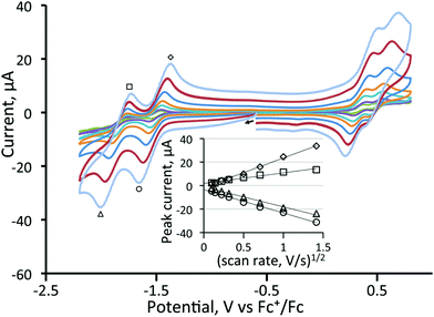
For the dcpm cluster 5 (Fig. 4), two oxidation waves are seen, and both exhibited some reversibility. The first oxidation occurs at 0.34 V (ΔE = 140 mV) and the second at 0.51 V (ΔE = 140 mV). When the scan rate was varied from 0.01 to 2 V s−1 for 4 and 5, no additional features were observed. Plots of anodic and cathodic peak currents of the first reductive process against the square root of the scan rate both give straight lines (Fig. 4) indicating that they originate from diffusion-controlled one-electron processes. Thus for 5, it was possible to cycle through five different redox states with some degree of reversibility with total electron counts ranging from 48–52 electrons.
In summary, while the electrochemical behaviour of the series of clusters [Fe3(CO)9(μ3-E)2] (E = S, Se, Te) are quite similar, the better reversibility of the reductive chemistry of tellurium cluster 1, and the continued reversibility of the two one-electron reductive processes upon addition of a diphosphine, make the tellurium-containing clusters potential candidates for proton reduction catalysts.
Density functional theory (DFT) calculations
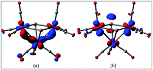
In order to gain more insight into the nature of the tellurium-capped clusters upon one- and two-electron reduction we have carried out a series of DFT calculations on [Fe3(CO)9(μ3-Te)2] (1), 1− and 12−. Selected atomic charges and Wiberg bond indices are given in Tables S1 and S2.† The HOMO and LUMO of the neutral cluster are shown in Fig. 5. The HOMO (Fig. 5a) consists primarily of Fe–Fe bonding character in the two formal iron–iron bonds. The LUMO (Fig. 5b) is of most interest with respect to the observed reduction chemistry and consists primarily of Fe–Fe antibonding character in addition to some Fe–Te antibonding character. This suggests that partial or complete population of this orbital will lead to an expansion of both the iron–iron and iron–tellurium bonds.The addition of a single electron to 1 results in significant lengthening (0.923 Å) of one of the Fe–Fe bonds to give the doublet radical anion, 21˙−. Adding a second electron gives the open-shell triplet dianion (312−) and results in a slight lengthening of the remaining Fe–Fe bond and a slight shortening of the first Fe–Fe bond. This triplet dianion is calculated to be 8.8 kcal mol−1 more stable than the closed-shell singlet dianion (112−), which undergoes cleavage of one wingtip Fe–Te bond, leading to polyhedral expansion of the cluster core. An open-shell singlet dianion was also considered, but this species was not stable and collapsed to the closed-shell singlet. These results are summarized in Fig. 6.
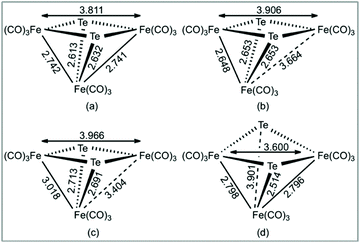 | ||
| Fig. 6 B3LYP/6-31+G(d′), SDD[Fe,Te] optimized Fe–Fe and Fe–Te internuclear distances in (a) 1, (b) 1−, (c) 312−, and (d) 112−. Internuclear distances in Angstroms. | ||
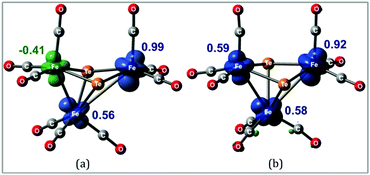
Hence, it appears that upon addition of two electrons to 1, the major structural change is the loss of one of the Fe–Fe bonding interactions with the formation of the diradical 312− in which the triiron core is held together by two capping tellurium atoms. This is most likely the reason that this process shows such good reversibility on the electrochemical time scale as neither ligand loss nor cluster fragmentation is facile. The spin density in 11− and 312− is primarily distributed over the three iron centers as depicted in Fig. 7. These metal sites are electron rich and are expected to help direct the initial site of protonation.
Spectroelectrochemical IR measurements on [Fe3(CO)9(μ3-Te)2] 1 showed that the monoanion 1− is reasonably stable during inert conditions (a total lifetime of ca. 30 min) while the corresponding dianion 12− was found to be relatively unstable and was rapidly deposited on the electrode surface. Neither 1− nor 12 were accessed by chemical means (cf. ESI†).
While we have not carried out DFT calculations for any of the related diphosphine complexes 4–6, we make the assumption that their behaviour is similar, with the diphosphine most likely spanning the relatively unaltered iron–iron bond after two-electron reduction.32
Electrocatalytic studies
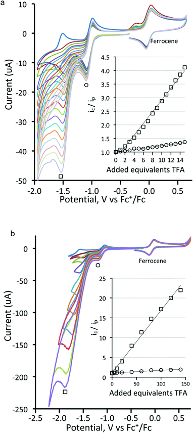
Before electrocatalytic studies were undertaken, all complexes were screened for their reactivity towards TsOH in CH2Cl2. Under a nitrogen atmosphere, no significant changes in the IR spectra were noted upon addition of acid, indicating that the neutral complexes are not readily protonated under the utilised conditions of catalysis (vide infra). In the presence of oxygen, the addition of acid to the diphosphine-bridged complexes 4–6 did lead to the slow formation of new absorptions in the IR spectra, but these were associated with the respective cations (vide supra), showing that oxidation rather than protonation was the dominant feature.In the ensuing electrocatalytic studies, all measurements were conducted on 1 mM solutions of cluster. The electrocatalytic activity of [Fe3(CO)9(μ3-Te)2] (1) towards proton reduction was investigated in the presence of TFA. Fig. 8 shows the cyclic voltammograms upon addition of a few equivalents of acid to a CH2Cl2 solution of 1. It would appear that the reduced complex is protonated and that the protonated complex is more easily reduced than the parent compound but the second reduction becomes lest reversible. Additional increases in acid increase the peak current for the second reduction (Fig. 9), which is characteristic of electrocatalytic proton reduction. Fig. S3 (ESI†) shows the cyclic voltammograms of the complex, of pure acid, and of acid with the complex. The reduction potential is 0.5 V more positive in the presence of the catalyst. An additional reduction peak is also seen at Ep = −2.20 V (Fig. S3(a)†), which increases sharply with acid concentration, because the catalysis becomes competitive at this potential due to the direct reduction of acid by the electrode. This reduction peak was not investigated further. Similar results are obtained using tosylic acid (TsOH) with small increases in catalytic current at the first reduction potential and larger increases at the second reduction potential, as seen in Fig. S4 (ESI†). The catalytic activity of 1 is thus akin to that which we have previously noted for [Fe4(CO)10(κ2-dppn)(μ4-O)] {dppn = 1,8-bis(diphenylphosphino)naphthalene}.24
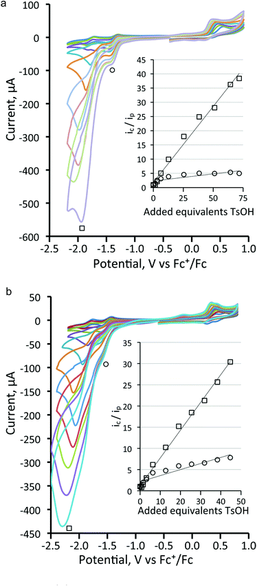
Next, the proton reduction ability of the phosphine derivatives 3–5 was considered. The behaviour of the PPh3-substituted cluster 3 (Fig. S5, ESI†), [Fe3(CO)7(μ3-Te)2(μ-dppm)] (4) (Fig. 10a) and [Fe3(CO)7(μ3-Te)2(μ-dcpm)] (5) (Fig. 10b) are similar to that of 1 with some reduction activity at the first reduction potential, but greater activity at the second reduction. Both were examined. In each case, after addition of one equivalent of acid a catalytic response was observed and the chemical reversibility of the first and second reductions disappeared completely. The dppm derivative 4 is particularly well-behaved. At the first reduction potential, there is little activity, but the dianion shows high activity and is able to reduce protons very efficiently and is not saturated even upon addition of 70 equivalents of acid. Cluster 5, containing the more electron-donating dcpm ligand, behaves similarly until the addition of ca. 20 equivalents of acid (light blue curve, Fig. 10b), after which a second catalytic pathway becomes active at slightly more negative potentials (ca. −2.2 V). This leads to a significant broadening of the CV traces at higher acid concentrations as the catalytic activities of these two separate species overlap. This also leads to large currents as compared to the dppm-derivative 4. Thus, after addition of ca. 40 equivalents of acid, the total peak currents for 4 and 5 are ca. 380 μA and 470 μA, respectively (see insets, Fig. 10a and b, for details). For both 4 and 5, the height of the oxidation peak remains uniform upon addition of acid and is shifted to less positive values, indicating that the catalysts are stable on the time frame of the experiments. A further notable feature is that there are no new reduction peaks at more positive potentials than the first reduction of the neutral complex, supporting the IR protonation studies that suggest that neither complex is rapidly protonated under the conditions of the catalytic studies. This electrocatalytic proton reduction behaviour is similar to that found for analogous sulfur and selenium clusters,32 but hydrogen generation occurs at significantly less negative potentials (ca. 0.25 and 0.14 V, respectively) than for the lighter analogues, while peak currents are also significantly higher for the telluride clusters under comparable experimental conditions. Table 2 summarises the electrocatalytic data, listing observed reduction potentials and associated derived rate constants (cf. ESI†) for proton reduction at these potentials. On the basis of the electrochemical and electrocatalytic results presented above, we propose that a series of interlinked catalytic cycles are operating (Scheme 3). The relative rates of these catalytic cyles will be dependent on the applied chemical potential, acid concentration and the nature of the substituents at the triiron center. The neutral 50-electron clusters are not catalysts. One-electron reduction affords the 51-electron radicals [Fe3(CO)7(μ3-Te)2(L2)]˙− and some catalytic activity is seen at this potential. This suggests that these radical anions can be protonated, with higher currents being observed as the electron-releasing nature of the L2 moiety increases: dcpm (5) > dppm (4) > (CO)(PPh3) (3) > (CO)2 (1). This may relate to the increasing rate of protonation of the triiron centre upon successive carbonyl substitutions. In this respect, this behaviour differs from that noted for [Fe4(CO)10(κ2-dppn)(μ4-O)],24 where the one-electron reduced cluster shows no catalytic activity, but it is similar to the behaviour of [Fe4(CO)12(μ4-N)]−,30 [Fe4(CO)12(μ4-C)]2−,31 and [Fe3(CO)7(μ3-E)2(μ-dppm)] (E = S, Se)26,32 where the activity is also seen at the first reduction potential. The order of electron/proton addition after formation of the putative [HFe3(CO)7(μ3-Te)2(μ-diphosphine)] intermediate is unknown but in view of the slow rates of protonation of the neutral complexes a second reduction followed by protonation and hydrogen release seems most likely.
 | ||
| Scheme 3 Proposed electrocatalytic proton reduction pathways mediated by [Fe3(CO)7(μ3-Te)2(L2)] (L2 = diphosphine). | ||
| Complex (250 mV s−1 except 3, 6 at 200 mV s−1 TsOH unless otherwise noted) | E 1 | Slope 1 ic/ipvs. [H+] | k 1, M−2 s−1 | E 2 | Slope 2 ic/ipvs. [H+] | k 2, 103 M−2 s−1 |
|---|---|---|---|---|---|---|
| [Fe3(CO)9(μ3-Te)2] (1) | −1.06 | 0.0165 | 130 | −1.54 | 0.0694 | 2.4 |
| [Fe3(CO)9(μ3-Te)2] (1) + TFA | −1.09 | 0.0067 | 22 | −1.51 | 0.157 | 12 |
| [Fe3(CO)8(μ3-Te)2(PPh3)] (3) | −1.39 | 0.0094 | 35 | −2.15 | 0.245 | 24 |
| [Fe3(CO)7(μ3-Te)2(μ-dppm)] (4) | −1.44 | 0.0426 | 900 | −1.90 | 0.531 | 140 |
| [Fe3(CO)7(μ3-Te)2(μ-dcpm)] (5) | −1.61 | 0.124 | 7600 | −2.03 | 0.644 | 200 |
| [Fe3(CO)8(μ3-Te)2(μ-dppa)] (6) | −1.14 | 0.0499 | 980 | −1.64 | 0.503 | 100 |
| [Fe3(CO)9(μ3-Se)2]32 | −1.14 | 0.0073 | 26 | −2.02 | 0.324 | 52 |
| [Fe3(CO)7(μ3-S)2(μ-dppm)]32 | −1.37 | 0.0135 | 90 | −1.85 | 0.272 | 37 |
| [Fe3(CO)7(μ3-Se)2(μ-dppm)]32 | −1.41 | 0.0548 | 1500 | Shifts | 0.252 | 31 |
While the ditelluride clusters are only relatively poor proton reduction catalysts at their first reduction potentials, the doubly reduced 52-electron clusters [Fe3(CO)7(μ3-Te)2(μ-diphosphine)]2−, especially clusters 4 and 5, show very large electron uptake at their second reduction potential. DFT calculations on 12− (vide supra) show that it exists in its triplet form and thus we suggest that the triplet dianions [Fe3(CO)7(μ3-Te)2(μ-diphosphine)]2− undergo facile addition of two protons to generate the corresponding neutral 52-electron clusters [H2Fe3(CO)7(μ3-Te)2(μ-diphosphine)]. Even upon addition of 70 equivalents of TsOH to the dppm derivative 4 (Fig. 10a) no evidence of saturation associated with rate-determining loss of hydrogen was noted, suggesting that hydrogen loss is facile and leads to regeneration of the neutral cluster. For the more electron-rich dcpm derivative 5, at high acid concentrations (>20 equivalents) a third hydrogen generation process appears at more negative potentials (ca. −2.2 V) and this may be associated with the less facile loss of hydrogen from [H2Fe3(CO)7(μ3-Te)2(μ-diphosphine)] and its subsequent reduction leading to hydrogen elimination. For the less electron-rich clusters 1 (Fig. 8) and 3 (Fig. S3†), the major hydrogen generation also occurs at potentials greater than those required for generation of the dianions. This suggests that there is also a pathway whereby these dianions (e.g.12−) are not sufficiently basic to undergo double protonation but rather react with acid to give [HFe3(CO)8(L)(μ3-Te)2]− (L = CO, PPh3), which are further reduced to [HFe3(CO)8(L)(μ3-Te)2]2− before the second protonation and hydrogen loss. These potential proton reduction pathways are summarized in Scheme 3.
Summary and conclusions
In this work we have investigated the utility of the non-biological element tellurium as a replacement for the widely biologically-utilized lighter chalcogenides sulfur and selenium in the realm of proton-reduction catalysis. Our first target in this respect was the 50-electron ditelluride cluster [Fe3(CO)9(μ3-Te)2] (1) and selected phosphine and diphosphine derivatives, that may be compared to related sulfur and selenium-clusters that are able to act as proton reduction catalysts.The synthesis of these clusters is relatively facile, and they show good stability in both the solid state and solution. Electrochemical studies reveal that each cluster shows two reductive processes. The first of these has good reversibility in all cases, showing that the 51-electron radical anions are quite stable. DFT calculations on 1− reveal that the only major structural change is an elongation of one of the Fe–Te bonding interactions. The chemical reversibility of the second reduction process is highly dependent upon the nature of the supporting ligands. Thus, for the parent cluster 1 and the diphosphine derivatives 4 and 5 this reduction is reversible, but for the PPh3 complex 3 it is completely irreversible. DFT calculations on 12− suggest that addition of the second electron affords an open-shell triplet with two elongated Fe–Te bonds that is more stable than the analogous closed-shell dianion. In all cases the first reductive process occurs at more positive potentials than that of analogous sulfur and selenium-containing clusters32 and the availability (at relatively low potentials) and stability of the 52-electron dianions, [Fe3(CO)7(μ3-Te)2(μ-diphosphine)]2−, contrasts with the lighter chalcogenide analogues that are either not accessible (within the solvent window) or show little stability.
Electrocatalytic proton reduction was assessed in dichloromethane using trifluoroacetic acid (TFA) or p-toluenesulfonic acid (TsOH) as the proton source. None of the iron telluride clusters react with these acids on the time scale of the catalysis experiments, but all are able to act as proton reduction catalysts at both their first and second reduction potentials. Electron uptake at the first reduction potential is relatively small in all instances, while in contrast uptake at the second potential is much larger, indicating that the open-shell triplet dianions are efficient catalysts. The catalytic overpotential increases upon successive phosphine substitution but so does the electron uptake and we attribute this to an increasing proton binding ability. For [Fe3(CO)7(μ3-Te)2(μ-dcpm)] (5), a further electron uptake appears at high acid concentrations at a slightly more negative potential than its second reduction, suggesting that H2 loss from the putative intermediates [H2Fe3(CO)7(μ3-Te)2(μ-dcpm)] or [H3Fe3(CO)7(μ3-Te)2(μ-dcpm)]+ may become rate-limiting. On the basis of the electrocatalytic results a mechanistic scheme has been developed in order to understand fully the role of the supporting ligands on the preferred route(s) to H2 production and release.
This work shows that tellurium-containing iron complexes offer some benefits over the extensively studied sulfur and selenium-containing species as proton reduction catalysts. Reduction potentials are more positive for the tellurium complexes and the reduced species show better stability. This finding is in accord with the works of Song36,37 and Weigand68,69 who have studied series of diiron complexes exchanging sulfur, selenium and tellurium. This suggests that further study of iron–tellurium complexes as proton-reduction catalysts is warranted, and we are currently investigating the proton reduction ability of a series of related [Fe3(CO)8(μ3-Te)2(κ2-diphosphine)] 52-electron complexes.
Conflicts of interest
There are no conflicts of interest to declare.Acknowledgements
AR thanks the European Commission for the award of an Erasmus Mundus pre-doctoral fellowship. GH and EN thank the Royal Society for an International Exchange Award. JBL thanks the Beloit Summer Science Scholars program. MGR thanks the Robert A. Welch Foundation (Grant B-1093-MGR) for financial support. Computational resources through the High-Performance Computing Services and CASCaM at the University of North Texas are acknowledged, and we thank Prof. Michael B. Hall (Texas A&M University) for providing us a copy of his JIMP2 program, which was used to prepare the geometry-optimized structures reported here. We are indebted to Dr Luca Zuppiroli (University of Bologna) for recording the high resolution mass spectra of complexes 5 and 6. We thank Dr Georgia Orton (King's College London) and Prof. Frantisek Hartl (University of Reading) for spectroelectrochemical measurements on complex 1.References
- C. Tard and C. Pickett, Chem. Rev., 2009, 109, 2245–2274 CrossRef CAS PubMed.
- J. A. Cracknell, K. A. Vincent and F. A. Armstrong, Chem. Rev., 2008, 108, 2439–2461 CrossRef CAS PubMed.
- P. Vignais and B. O. Billoud, Chem. Rev., 2007, 107, 4206–4272 CrossRef CAS PubMed.
- M. Frey, ChemBioChem, 2002, 3, 153–160 CrossRef CAS PubMed.
- J. Peters, Curr. Opin. Struct. Biol., 1999, 9, 670–676 CrossRef CAS PubMed.
- Y. Nicolet, C. Cavazza and J. C. Fontecilla-Camps, J. Inorg. Biochem., 2002, 91, 1–87 CrossRef CAS.
- J. Peters, W. Lanzilotta and B. Lemon, Science, 1998, 282, 1853–1858 CrossRef CAS PubMed.
- I. P. Georgakaki, L. M. Thomson, E. J. Lyon, M. B. Hall and M. Y. Darensbourg, Coord. Chem. Rev., 2003, 255, 238–239 Search PubMed.
- D. J. Evans and C. J. Pickett, Chem. Soc. Rev., 2003, 32, 268–275 RSC.
- T. B. Rauchfuss, Inorg. Chem., 2004, 43, 14–26 CrossRef CAS PubMed.
- L. Sun, B. Åkermark and S. Ott, Coord. Chem. Rev., 2005, 249, 1653–1663 CrossRef CAS.
- Y. Nicolet, C. Piras, P. Legrand, C. H. Hatchikian and J. C. Fontecilla-Camps, Structure, 1999, 7, 13–23 CrossRef CAS PubMed.
- B. J. Lemon and J. W. Peters, Biochemistry, 1999, 38, 12969–12973 CrossRef CAS PubMed.
- M. Bruschi, C. Greco, M. Kaukonen, P. Fantucci, U. Ryde and L. De Gioia, Angew. Chem., Int. Ed., 2009, 48, 3503–3506 CrossRef CAS PubMed.
- C. Greco, P. Fantucci, L. De Gioia, R. S. Bertoa, M. Bruschi, J. Talarmin and P. Schollhammer, Dalton Trans., 2010, 39, 7320–7329 RSC.
- C. Greco, G. Zampella, L. Bertini, M. Bruschi, P. Fantucci and L. De Gioia, Inorg. Chem., 2007, 46, 108–116 CrossRef CAS PubMed.
- P. Surawatanawong, J. T. Tye, M. Y. Darensbourg and M. B. Hall, Dalton Trans., 2010, 39, 3093–3104 RSC.
- E. Garcin, X. Vernede, E. C. Hatchikian, A. Volbeda, M. Frey and J. C. Fontecilla-Camps, Structure, 1999, 7, 557–566 CrossRef CAS PubMed.
- H. S. Shafaat, O. Rüdiger, H. Ogata and W. Lubitz, Biochim. Biophys. Acta, 2013, 1827, 986–1002 CrossRef CAS PubMed.
- D. Schilter, M. J. Nilges, M. Chakrabarti, P. A. Lindahl, T. B. Rauchfuss and M. Stein, Inorg. Chem., 2012, 51, 2338–2348 CrossRef CAS PubMed.
- Z. Li, Y. Ohki and K. Tatsumi, J. Am. Chem. Soc., 2005, 127, 8950–8951 CrossRef CAS PubMed.
- A. Rahaman, S. Ghosh, D. Unwin, S. B. Modi, K. B. Holt, S. E. Kabir, E. Nordlander, M. G. Richmond and G. Hogarth, Organometallics, 2014, 33, 1356–1366 CrossRef CAS.
- S. Ghosh, G. Hogarth, K. B. Holt, S. E. Kabir, A. Rahaman and D. Unwin, Chem. Commun., 2011, 47, 11222–11224 RSC.
- S. Ghosh, K. B. Holt, S. E. Kabir, M. G. Richmond and G. Hogarth, Dalton Trans., 2015, 44, 5160–5169 RSC.
- C. Tard, X. Liu, D. L. Hughes and C. J. Pickett, Chem. Commun., 2005, 133–135 RSC.
- M. Kaiser and G. Knör, Eur. J. Inorg. Chem., 2015, 4199–4206 CrossRef CAS PubMed.
- Z. Li, X. Zeng, Z. Niu and X. Liu, Electrochim. Acta, 2009, 54, 3638–3644 CrossRef CAS.
- C. A. Mebi, K. E. Brigance and R. B. Bowman, J. Braz. Chem. Soc., 2012, 23, 186–189 CrossRef CAS.
- W. Gao, J. Sun, M. Li, T. Åkermark, K. Romare, L. Sun and B. Åkermark, Eur. J. Inorg. Chem., 2011, 1100–1105 CrossRef CAS.
- M. D. Rail and L. A. Berben, J. Am. Chem. Soc., 2011, 133, 18577–18579 CrossRef CAS PubMed.
- A. D. Nguyen, M. Rail, M. Shanmugam, J. C. Fettinger and L. A. Berben, Inorg. Chem., 2013, 52, 12847–12854 CrossRef CAS PubMed.
- A. Rahaman, S. Ghosh, S. Basak-Modi, A. F. A. Magied, M. Haukka, G. C. Lisensky, M. G. Richmond, E. Nordlander and G. Hogarth, J. Organomet. Chem., 2019, 880, 213–222 CrossRef CAS.
- R. L. R. Cunha, I. E. Gouvea and L. Juliano, Ann. Acad. Bras. Cienc., 2009, 81, 393–407 CrossRef CAS PubMed.
- S. E. Ramadan, A. A. Razak, A. M. Ragab and M. El-Meleigy, Biol. Trace Elem. Res., 1989, 20, 225–232 CrossRef CAS PubMed.
- H. L. Seng and R. T. E. Tiekink, Appl. Organomet. Chem., 2012, 26, 655–662 CrossRef CAS.
- L. C. Song, Q.-L. Li, Z.-H. Feng, X.-J. Sun, Z.-J. Xie and H.-B. Song, Dalton Trans., 2013, 42, 1612–1626 RSC.
- L. C. Song, J. X. Sun, J. G. Jia, M. M. Wang and B. H. Song, J. Organomet. Chem., 2014, 761, 10–19 CrossRef CAS.
- W. Hieber and J. Z. Gruber, Anorg. Allg. Chem., 1958, 296, 91–103 CrossRef CAS.
- P. L. Stanghellini, G. Cetini, O. Gambino and R. Rosetti, Inorg. Chim. Acta, 1969, 3, 651–654 CrossRef CAS.
- P. L. Stanghellini, G. Cetini, O. Gambino and R. Rosetti, Inorg. Chim. Acta, 1968, 2, 433–438 CrossRef.
- G. Cetini, P. L. Stanghellini, R. Rosetti and O. Gambino, J. Organomet. Chem., 1968, 15, 373–381 CrossRef CAS.
- D. A. Lesch and T. B. Rauchfuss, Inorg. Chem., 1981, 20, 3583–3585 CrossRef CAS.
- D. A. Lesch and T. B. Rauchfuss, Organometallics, 1982, 1, 499–506 CrossRef CAS.
- W. Victor, D. A. Lesch and T. B. Rauchfuss, J. Am. Chem. Soc., 1982, 104, 1290–1295 CrossRef.
- D. A. Lesch and T. B. Rauchfuss, Inorg. Chem., 1983, 22, 1854–1857 CrossRef CAS.
- L. E. Bogan, I. Jr, D. A. Lesch and T. B. Rauchfuss, J. Organomet. Chem., 1983, 250, 429–438 CrossRef CAS.
- S. Chatterjee, S. K. Patel and S. M. Mobin, J. Organomet. Chem., 2011, 696, 1782–1786 CrossRef CAS.
- S. Chatterjee, S. K. Patel, V. Tirkey and S. M. Mobin, J. Organomet. Chem., 2012, 699, 12 CrossRef CAS.
- P. Mathur, Adv. Organomet. Chem., 1997, 41, 243–314 CrossRef CAS.
- P. Mathur and I. J. Mavunkal, J. Organomet. Chem., 1988, 350, 251–256 CrossRef CAS.
- P. Mathur, I. J. Mavunkal and V. Rugmini, J. Organomet. Chem., 1989, 367, 243–248 CrossRef CAS.
- P. Mathur and V. D. Reddy, J. Organomet. Chem., 1990, 385, 363–368 CrossRef CAS.
- A. L. Rheingold, R. L. Ostrander and P. Mathur, Acta Crystallogr., Sect. C: Cryst. Struct. Commun., 1993, 49, 1741–1743 CrossRef.
- P. Mathur, A. K. Bhunia, A. Kumar, S. Chatterjee and S. M. Mobin, Organometallics, 2002, 21, 2215–2218 CrossRef CAS.
- P. Mathur, D. K. Rai, R. Shyam, B. Pathak, S. Boodida and S. M. Mobin, RSC Adv., 2013, 3, 26025–26034 RSC.
- A. Rahaman, G. C. Lisensky, D. A. Tocher, M. G. Richmond, G. Hogarth and E. Nordlander, J. Organomet. Chem., 2018, 867, 381–390 CrossRef CAS.
- R. R. Gagné, C. A. Koval and G. C. Lisensky, Inorg. Chem., 1980, 19, 2854–2855 CrossRef.
- M. J. Frisch, et al., Gaussian 09, Revision E.01, Gaussian, Inc., Wallingford, CT, USA, 2009 Search PubMed.
- A. D. Becke, J. Chem. Phys., 1993, 98, 5648–5652 CrossRef CAS.
- C. Lee, W. Yang and R. G. Parr, Phys. Rev. B: Condens. Matter, 1988, 37, 785–789 CrossRef CAS PubMed.
- M. B. Hall and R. F. Fenske, Inorg. Chem., 1972, 11, 768–775 CrossRef CAS.
- J. Manson, C. E. Webster, L. M. Pérez and M. Hall, Jimp 2, https://www.chem.tamu.edu/jimp2, accessed May 2020 Search PubMed.
- G. Hogarth, N. J. Taylor, A. J. Carty and A. Meyer, J. Chem. Soc., Chem. Commun., 1988, 834–836 RSC.
- M. Kaiser and G. Knör, Eur. J. Inorg. Chem., 2015, 4199–4206 CrossRef CAS PubMed.
- D. Cauzzi, C. Graiff, M. Lanfranchi, G. Predieri and A. Tiripicchio, J. Organomet. Chem., 1997, 536–537, 497–507 CrossRef.
- L. Marko’, T. Madach and H. Vahrenkamp, J. Organomet. Chem., 1980, 190, C67 CrossRef.
- S. N. Konchenco, A. V. Virovets and S. V. Thachev, Zh. Strukt. Khim., 1998, 39, 894–898 Search PubMed.
- K. M. Harb, U. P. Apfel, J. Kubel, H. Görls, G. A. N. Felton, T. Sakamoto, D. H. Evans, R. S. Glass, D. L. Lichtenberger, M. El-Khateeb and W. Weigand, Organometallics, 2009, 28, 6666–6675 CrossRef.
- M. K. Harb, U. P. Apfel, T. Sakamoto, M. El-Khateeb and W. Weigand, Eur. J. Inorg. Chem., 2011, 986–993 CrossRef CAS.
Footnote |
| † Electronic supplementary information (ESI) available. See DOI: 10.1039/d0dt00556h |
| This journal is © The Royal Society of Chemistry 2020 |

