
 Open Access Article
 This Open Access Article is licensed under a Creative Commons Attribution-Non Commercial 3.0 Unported Licence
Mechanistic insights into photocatalysis and over two days of stable H2 generation in electrocatalysis by a molecular cobalt catalyst immobilized on TiO2†
Nicola
Weder
 a,
Benjamin
Probst
a,
Laurent
Sévery
a,
Ricardo J.
Fernández-Terán
a,
Jan
Beckord
b,
Olivier
Blacque
a,
S. David
Tilley
a,
Peter
Hamm
a,
Jürg
Osterwalder
b and
Roger
Alberto
*a
a,
Benjamin
Probst
a,
Laurent
Sévery
a,
Ricardo J.
Fernández-Terán
a,
Jan
Beckord
b,
Olivier
Blacque
a,
S. David
Tilley
a,
Peter
Hamm
a,
Jürg
Osterwalder
b and
Roger
Alberto
*a
aDepartment of Chemistry, University of Zurich, Winterthurerstrasse 190, 8057 Zurich, Switzerland. E-mail: ariel@chem.uzh.ch
bDepartment of Physics, University of Zurich, Winterthurerstrasse 190, 8057 Zurich, Switzerland
First published on 2nd April 2020
Abstract
To employ molecular water reduction catalysts (WRC) in a heterogeneous setup, a stable, macrocyclic CoIII–polypyridyl WRC containing two phosphonic acid groups was anchored on TiO2 to investigate photo- and electrocatalytic proton reduction. Photocatalytic investigations included kinetic studies of the electron transfer from the reduced photosensitizer to the WRC as well as H2-evolution measurements. Linear sweep voltammetry (LSV) performed on the immobilized WRC on a TiO2-coated FTO-glass electrode showed an onset potential of −0.6 V vs. SHE at pH = 5 for proton reduction, while operando UV/VIS confirmed the reduced CoI-species as the key catalytic intermediate. Finally, chronoamperometric investigations combined with XPS studies and ICP-MS studies of electrode and electrolyte revealed stable binding of the WRC on the electrode under catalytic conditions and constant H2-formation over the period of two days.
Introduction
The ongoing research on photocatalytic water splitting – a promising solution to comply with the world's increasing power demand, as well as an efficient way to store solar energy over a long period of time1 – has brought up different systems and setups to approach this challenge by now. One can roughly subdivide this research into molecular catalysts,2 mostly transition metal complexes, inspired by natural photo- and redox active systems,3,4 and surface-catalyzed approaches,5,6 where the electrode constitutes the catalytic site itself as in a photoelectrochemical (PEC) cell. The common basis of both systems consists of a light harvesting unit, making the light-induced charge separation, and shuffling electrons from the oxidative to the reductive half-reaction while overcoming the 1.23 eV (+overpotential) required for the full reaction.Molecular water reduction catalysts (WRC) featuring transition metals such as Fe,7 Ni,8 Co (ref. 9–13) or Mo (ref. 14) as metal-cores, coordinated by either N- or P-containing ligands15–20 have proven themselves as solid candidates for water reduction. Reported H2 turnover frequencies as high as 100![[thin space (1/6-em)]](https://www.rsc.org/images/entities/char_2009.gif) 000 s−1 spearhead the catalytic activity of all water reductive systems.21 Amongst the most promising WRCs, one often finds cobalt–polypyridyl complexes,22,23 which excel in reported turnover numbers (TON) as high as 80000 H2 WRC−1 and offer a large playground for ligand-modifications, tuning the electrochemical properties of the metal center.24
000 s−1 spearhead the catalytic activity of all water reductive systems.21 Amongst the most promising WRCs, one often finds cobalt–polypyridyl complexes,22,23 which excel in reported turnover numbers (TON) as high as 80000 H2 WRC−1 and offer a large playground for ligand-modifications, tuning the electrochemical properties of the metal center.24
Despite excellent properties, molecular catalysts bear some disadvantages compared to surface catalyzed systems, especially regarding long-term stability as well as applicability in a full water splitting system. The lack of separation of the two half-reactions in a homogeneous system leads to electron short-cuts, which quench the catalytic cycle.25 Separation would lead to control of the direction of electron flow, as it is the case in a PEC cell.26–28 To integrate the high catalytic rates of molecular catalysts in a (so far surface-catalyzed) two-cell system, the molecular catalyst must be adsorbed on the electrode. Depending on the substrate, the WRC is either bound via physical adsorption such as hydrophobic interactions29 or covalently, whereby the anchoring group must be adjusted to the properties of the respective surfaces.
This work presents a novel, molecular and highly stable cobalt–polypyridyl WRC with two phosphonic acid anchoring groups for covalent bonding to TiO2, as this material is often used as an optically transparent passivation layer in PEC cells.30,31 Transient absorption and H2-evolution experiments under photocatalytic conditions were performed to study the influence of the immobilization on the catalytic activity and proton reduction mechanism. Spectro-electrochemical investigations in a three-electrode setup allowed to detect the onset potential of H2-evolution and to acquire the absorption spectra of a CoI-intermediate. Finally, chronoamperometry in combination with XPS studies of the immobilized catalyst and ICP-MS of the electrolyte showed long-term catalytic stability of the immobilized WRC.
Synthesis & immobilization
The cyclic dimethyl-pyrphyrin ligand (3) was synthesized via double lithiation of 6,6′-dibromobipyridine (1) and reaction with ethyl iodide to obtain 6,6′-diethylbipyridine (2). Deprotonation of the CH2-position and quenching with another equivalent of 1 led to the pure cyclic pyrphyrin ligand 3 as a mixture of cis- and trans isomers (Scheme 1). | ||
| Scheme 1 General reaction scheme for ligand and complex syntheses. Conditions: i) BuLi, EtI, THF, −95 °C, 58%; ii) LDA, 6,6′-dibromobipyridine, THF, −80 °C, 88%; iii) KOtBu, diethyl vinylphosphonate, THF, −80 °C to RT, 12 h, 30%; iv) CoBr2, MeOH, O2, RT; v) TMSBr, MeCN, 42 °C; 62% over two steps; vi) KOtBu, MeI, THF, −80 °C to RT, 1 h, 56%; vii) CoBr2, MeOH, O2, r.t., 78%; viii) CoBr2, MeOH, O2, RT, 51%; ix) Zn(OAc)2, MeOH, RT, 99%; x) TMSBr, MeCN, 48 °C, 85%. | ||
Although ligand 3 is stable in its free form, the addition of cobalt under air led to rapid hydroxylation of the bridging carbons, yielding [CoIII(di-(methyl-hydroxy)-pyrphyrin)Br2]Br (9), selectively in trans configuration as evident from an X-ray structure analysis (vide infra). Notably, cobalt is oxidized during the complexation from CoII to CoIII, as it is the case for all pyrphyrin-type ligands reported in this work. However, to increase solubility for the studies in aqueous solutions, all complexes were reduced in situ with aq. ascorbic acid (0.1 M) for further studies. Complex 9 was successfully crystallized as both, CoIII as well as CoII (ESI†), the latter one by interface solvent diffusion method, after layering a solution of 9 in aq. ascorbic acid on top of an aq. sat. solution of KBr. The bridging CH-Me groups of ligand 3 are accessible for deprotonation by KOtBu in THF and subsequent nucleophilic addition or substitution reactions. The equilibrium of the deprotonation lies strongly on the protonated side, as shown by quenching experiments with methanol-d4 and analysis of the product by 1H NMR spectroscopy (Fig. S1†). Thus, it is important that the electrophile lacks any acidic protons to avoid the immediate quenching of the reaction. Hence, nucleophilic addition of deprotonated 3 to the double bond of diethyl vinylphosphonate led to the pyrphyrin ligand with protected anchoring groups (4) as a mixture of cis- and trans isomers in a ratio of 3:1 as evident from UHPLC-MS analysis. The desired cis-isomer was isolated by several subsequent precipitation- and crystallization procedures as described in the experimental part (Fig. 1). Complexation of cobalt to obtain compound 5 and cleavage of the phosphonic acid ester by TMSBr yielded the final product [CoIII(di-(Me–C2PO(OH)2)-pyrphyrin)Br2]Br (6).
 | ||
| Fig. 1 Crystal structure of 4 (H-atoms omitted for clarity; 50% thermal ellipsoid probability level). Colour code: C (grey), N (blue), O (red), P (orange). | ||
Complex 8 was synthesized as a reference compound to investigate the influence of the anchoring groups on the catalytic properties of the pyrphyrin complex. Deprotonation of the CH–Me groups in compound 3 with KOtBu and subsequent alkylation with methyl iodide led to 7. In order to obtain products 5, 6 and 8 with defined axial ligands and counter-ions, the crude complexes were dissolved in aq. sodium ascorbate to reduce the metal centers and facilitate axial ligand exchange. After addition of aq. sat. KBr, the metal centers were re-oxidized with elemental bromine, yielding a green precipitate of the complexes with exclusively Br− as axial ligands, respectively counter-ion. The zinc-complex 11 was synthesized as analogue to 6 with redox-inert metal centre. 1H, 13C and 31P NMR spectroscopy as well as HR-ESI, X-ray crystallography and CHN analyses confirm the authenticity of the complexes.
To study the immobilized catalyst, 6 was adsorbed on TiO2−substrate. Photocatalytic investigations were conducted with Aeroxide® P25 nanoparticles (Ø = 21 nm, 6@NP-TiO2), providing a high specific surface area (35–65 m2 g−1). This minimizes the required amount of NPs for a given WRC concentration, thus, enables maximal light flux. Electrocatalytic measurements were performed on an electrode consisting of rutile-nanopowder (Ø = 50 nm), spin-coated on TEC-15, 2.2 mm FTO glass substrate and annealed (6@m-TiO2). For adsorption of the catalyst, the respective substrates were immersed in an aq. solution of 6 in ascorbic acid (1 mM) at pH 5. The particles were separated by centrifugation and washed with doubly distilled water. The catalyst binds stably to the TiO2 substrate under acidic conditions up to pH 8 but desorbs at pH values above 9, as shown by desorption experiments of suspensions of loaded particles in water: after equilibration at a given pH from 2 to 12 the particles were centrifuged and the desorbed catalyst in the supernatant was quantitatively analyzed by HPLC (Fig. S2–S4†). The same type of measurements were performed on both the loading solution and the supernatant after catalyst adsorption, revealing a loading concentration of about 0.05 μmol catalyst per mg particles. This corresponds to a molecular footprint of (1.76 ± 0.17) nm2 or a loading density of (9.4 ± 0.9) × 10−2 nmol cm−2.
Photocatalytic experiments
Kinetic studies
Photocatalytic investigations were performed on a system containing [Ru(bipy)3]2+ as photosensitizer (PS), ascorbate (AscO−) as electron source and buffer and the water reduction catalyst (WRC). The WRCs are not water-soluble as CoIII, but in situ reduction by AscO− leads to good solubility. The axial halogens are weakly bound to CoII and dissociate upon dissolution in water.23,32,33In order to examine the electron transfer (ET) rates from the photochemically reduced PS (PS−) to WRC 8 in solution, and to the immobilized WRC 6@NP-TiO2, nanosecond transient absorption studies were performed on both systems containing WRC, PS and NaAscO. Scattering of the pump light on the nanoparticles limited the maximum feasible WRC concentration to ca. 5.6 μM, in order to minimize artefacts on the recorded kinetics. In all experiments, excitation of the PS below the bandgap of TiO2 was achieved by pumping with 532 nm instead of 355 nm, as commonly done in such systems.22,34 Due to both the lower extinction coefficient of the PS at 532 nm (ca. 7 times smaller than at 355 nm), and the decreased transmittance of the probing light (for on-particle measurements), the PS concentration was set to 300 μM, resulting in WRC-deficient conditions.
On the other hand, measurements in solution were performed under WRC excess conditions (50 μM PS and 0–200 μM WRC) to clearly evaluate the effect of increasing WRC concentration on the lifetime of PS−. A second set of measurements in solution was conducted under WRC-deficient conditions (300 μM PS, 0–6 μM WRC), to ascertain whether small variations in WRC concentrations exhibit a similar and quantifiable effect on the lifetime of the PS−.
The kinetic model used in this work is shown in Scheme 2. The excited PS (PS*) is reductively quenched by ascorbate (AscO−) with a rate constant k1, leading to simultaneous formation of an ascorbate radical (Asc˙). PS− can transfer its electron either to the WRC (productive ET, kCo) or back to Asc˙ (recombination, kR). The following sequence of electron and proton transfers, starting from CoI, is summarized by kH2, as it takes place on a much longer timescale than the initial electron transfers.33,35 This results in a 2nd order rate in CoI, which was taken into account for the second electron required for H2 production. Direct electron injection from PS− (RuII/I(bipy)3 = −1.2 V vs. SHE12) respectively PS* ( = −0.7 V vs. SHE36,37) into the conduction band of TiO2 (CB, ≃0.5 V vs. SHE at pH 5 (ref. 38 and 39)) would be thermodynamically favoured, leading to through-particle electron transfer.36 Since in this study PS is not co-grafted but diffusing from the solution to the surface, full coverage of the surface by the WRC prevents the TiO2 from direct interaction with the PS. Thus, productive electron transfer from PS− exclusively occurs to the immobilized CoII with the rate kCo. As cyclic cobalt polypyrphyrins such as 6 and 8 are reduced at −0.35 V vs. SHE, much earlier than cobaloxime (CoII/I = −0.6 V vs. SHE40,41) and below the CB potential of TiO2, electron injection via cobalt into the TiO2 can be excluded.
 | ||
| Scheme 2 Mechanistic model of the electron transfer reactions considered in the transient absorption (top) with the corresponding rate law equations on the bottom. | ||
The observable, ΔAbs (510 nm), is composed of the differential absorptions of PS− as well as CoI and CoII, weighted by their respective absorption coefficients and concentrations. The contributions of all other species to the transient signal were set to zero.33 The concentration of NaAscO was regarded as constant (0.085 M at pH 5) due to its large excess. Therefore,  was defined as k1·[AscO−]. All rate constants (including kCo) were globally fitted within one experiment, unless stated otherwise.
The transient spectra of the blank containing only PS and NaAscO (Fig. 2, top) and a sample containing additionally 100 μM WRC 8 (Fig. 2, bottom) show clear signatures of reduced PS−, Asc˙42 and singly reduced WRC (also in agreement with spectroelectro-chemical experiments). The isosbestic point at 461 nm of the blank, indicative of the presence of a single absorbing species (PS−), disappears after addition of catalyst. In the latter case, a shift of the absorption maximum from 510 nm to 475 nm within the first 20 μs is clearly visible. The normalized and fitted kinetic traces at 510 nm for the three experiments are shown in Fig. 3. The concentration profile and the raw data incl. residuals are shown in Fig. S5.† The WRC-excess experiment in solution (Fig. 3, top) shows the most evident effect of increasing WRC concentration on the observed kinetics. At early times (<2 μs), the rise in the transient signal is attributed to the formation of PS−.43,44 In absence of WRC, the reduced PS recombines with Asc˙ on a timescale of ca. 30 μs, leading to the disappearance of the signal at long times. In presence of WRC, a clear biphasic decay appears, originating from the initial, irreversible ET from PS− to the WRC. Between 1–10 μs, ΔAbs is dominated by the absorption of PS−, decaying via kR and kCo. Between 20 and 400 μs the predominant absorption maximum at 475 nm is attributed to the CoI species, before going back to CoII on a much longer timescale.
 | ||
| Fig. 2 Transient absorption spectra from 5 μs to 100 μs after the excitation in 5 μs intervals. Top: Blank containing 50 μM PS and 0.1 M NaAscO (pH 5) but no WRC; bottom: with the addition of 100 μM of WRC 8. | ||
 | ||
| Fig. 3 Kinetic absorption (510 nm) and globally fitted traces in logarithmic time scale. Top: WRC excess and in solution (50 μM PS, 8, 0.1 M NaAscO, pH 5); middle: WRC deficient and in solution, the inset illustrates the small effect of the WRC concentration on the kinetic trace, (300 μM PS, 8, 0.1 M NaAscO, pH 5); bottom: WRC deficient and on particles with a zoom on the relevant time interval (inset) to emphasize the effect of the WRC on the lifetime of PS− (300 μM PS, 6@NP-TiO2, 0.1 M NaAscO, pH 5). | ||
Under WRC-deficient conditions (Fig. 3, middle), we observe a faster overall decay of PS−, attributed to faster recombination with Asc˙ at higher PS concentrations. The effect of the WRC, while significantly smaller, is still evident (see inset). This leads to a faster decay of the PS− signal upon increased WRC concentration, albeit lacking the evident biphasic behavior observed under WRC-excess conditions.
Measurements performed with the adsorbed WRC (Fig. 3, bottom) show a similar behaviour to their solution counterparts under WRC-deficient conditions. A clear trend can be seen on an expanded region from 20 μs to 50 μs (inset of Fig. 3, bottom), which illustrates the effect of increasing WRC on the observed transient kinetics. The strong pump scattering signal, which becomes more prominent at higher nanoparticle concentrations, obscures the early kinetics of the on-particle measurements. This in turn prevents an accurate determination of k0 and k1, corresponding to processes taking place in timescales faster than 3.5 μs. In addition, both k0 and k1 are expected to be constant at a given PS and buffer concentration. Under these assumptions, k0 and  were fixed to the values obtained under WRC-deficient conditions in solution. The remaining free parameters (kCo, kR, and kH2) were fitted, starting from 3.5 μs and up to 100 μs. The resulting rate constants are summarized in Table 1.
At a first glance, the globally fitted rate constants obtained for all three experiments are reasonably similar, suggesting that the catalytic cycle is not significantly affected by immobilization of the catalyst. The value obtained for k1 and kR are comparable to previously reported values under similar conditions (2 × 10⁷ M−1 s−1 and 1 × 10⁹ M−1 s−1, respectively).45,46
Interestingly, PS− reduces the immobilized catalyst with a similar rate as in solution (kCo). Since terminal hydroxyl groups of TiO2 are predominantly protonated below pH 6.25,47 one could expect electrostatic repulsion of the cationic PS− (RuI) and the positively charged surface, slowing down the electron transfer. However, such an effect was not observed. Fast oxidation of PS− is crucial for a stable homogeneous photocatalytic system, since PS decomposition by ligand dissociation limits the performance of catalysis if the reduced state PS− remains unquenched. WRC 6 therefore enables fast oxidative quenching of the reduced PS−, both in solution and in a surface-immobilized system.
Photocatalysis
Photocatalytic H2 evolution experiments were performed in H2O at pH 5 with different WRC concentrations, [Ru(bipy)3]2+ as PS, AscO− as electron relay and buffer and tris-2-(carboxyethyl)-phosphine (TCEP) as sacrificial electron donor (SED).45 Water saturated argon as carrier gas was constantly flushed through the catalytic solution and the gas stream was periodically analyzed to obtain the time-dependent H2 evolution trace. The WRC loaded nanoparticles were suspended in an aqueous solution containing the PS, AscO− and TCEP. The amount of WRC loaded on the particles was adjusted to the corresponding amount of cobalt in a solution. The H2 evolution traces of WRC 6, 6@NP-TiO2 and 8 run through two subsequent peaks of maximal production rates (Fig. S6†). We attribute this shape to the formation of a cobalt-TCEP adduct as observed in earlier studies and reported in the literature.22,48 Catalytic experiments without TCEP, lacking the double peak, support this interpretation (Fig. S7†). However, accumulation of dehydroascorbic acid (DHA), which oxidatively quenches the reduced PS, limits performance of catalysis and results in lower TONs, as compared to experiments with TCEP.The turnover numbers (TON, [H2 WRC−1]) increase with decreasing catalyst concentrations (Fig. 4).12,22 At low cobalt concentrations, the TONs go up to 20–25 kTONs H2 WRC−1, outperforming most of the cobalt–polypyridyl WRCs investigated up to now. In terms of total amounts of H2 produced, the system performs less stable at low WRC concentrations. This can be related to the irreversible electron donor/relay system TCEP/AscO−, and the limited stability of PS− on the ms timescale where electron transfer to cobalt occurs at lower μM concentrations.12,49 PS degradation could be confirmed by HPLC analysis before and after catalysis as the stability limiting factor at low cobalt concentrations (see Fig. S8†). At the highest WRC concentrations, TCEP was almost completely oxidized to TCEPO, thereby limiting catalysis, as shown by 31P-NMR studies of the solution after catalysis (see Fig. S9†).
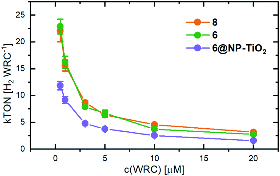 | ||
| Fig. 4 TONs determined from photocatalysis (in H2 WRC−1) of 8 (orange), 6 (green) and the adsorbed WRC on TiO2-nanoparticles (6@NP-TiO2, purple). All experiments contained 500 μM [Ru(bipy)3]2+, 0.1 M NaAscO and 0.1 M TCEP as electron relay and sacrificial electron donor, respectively. | ||
No significant performance differences are evident for both homogeneous catalysts 6 and 8. This is noteworthy since 6 contains internal acid groups, which could function as proton shuttles to the catalytic active site, an effect which was already reported in numerous studies.4,48,50,51 However, the absence of such an effect enables an objective comparison between the catalyst's performances in solution and adsorbed on TiO2, since an influence of the anchoring groups on the catalytic activity can be excluded.
Immobilization of the catalyst to 6@NP-TiO2 reduces the TONs to about 50% as compared to the fully homogeneous experiment. Any effect of the support was excluded by conducting the same experiment with 6 immobilized on the wide-bandgap material ZrO2, which performed equal to 6@NP-TiO2 (see Fig. S10†). We note that PS degradation is the limiting factor but oxidative quenching of PS− by the WRC occurs with the same rate as in solution. Therefore, the decreased TONs must result from the local excess of WRC on the particle surface but a complete lack in the solution between. In fact, as calculated by Fick's law (Fig. S11†), within the lifetime of the reduced PS− its maximal diffusion radius of 150 nm (ionic radius of 6.2 Å,52 half-life PS− of 30 μs, compare Fig. S5†) is less than half of the averaged distance between two particles (500 nm, with 5 μM WRC). Thus, a maximum of 20% of the PS lies within reach of any particle, the rest recombines via kR with an enhanced probability of PS degradation. For comparison, 47 WRC-molecules lie within the diffusion range of each PS− in a fully homogeneous system at the same WRC concentration. The H2 evolution experiments shown in Fig. S12† support experimentally this hypothesis: at a constant 6@NP-TiO2-concentration of 5 μM the TONs increase with decreasing loading density of the WRC on the particles. Thus, the higher number of particles supporting the same amount of catalyst leads to a wider distribution, thus, shorter average distance between two particles enhancing the probability for the PS− to be oxidatively quenched by a WRC.
Recycling experiments
Recycling experiments of the loaded NPs were performed with a catalytic suspension containing PS, NaAscO, TCEP and 6@NP-TiO2 corresponding to 5 μM WRC. After cessation of H2-formation after 2 days the NPs were separated by centrifugation and washed with H2O before being re-suspended in a fresh solution containing PS, NaAscO and TCEP. As shown in Fig. S13,† H2 evolution immediately restarts to a maximal rate of 50% of its original value and ceases after formation of a third the amount of H2 produced in the first run. The recycling procedure could be repeated two times, resulting in similar H2-formation drops between two subsequent runs. The fact that catalysis restarts attests the immobilized WRC not to be the limiting factor of the catalytic system. However, the decreased rate and amount of H2 produced in the 2nd and 3rd runs, respectively, indicate WRC desorption from the NPs during catalysis. In fact, ICP-MS analysis of the supernatant after the 1st run confirmed desorption of (37 ± 2) % of the immobilized catalyst. Thus 63% of the catalyst remained stably bound to the NPs in a solution containing both AscO− and TCEP in a 20000-fold excess, both known to compete for adsorption on TiO2.53
Summing up, we present the first example of an immobilized polypyridyl catalyst with high rates and more than 10 kTONs under photocatalytic conditions. The turnover frequencies (TOF [H2 WRC−1 s−1]) do not differ significantly between the catalysts 6 and 8 in solution. In accordance with the equivalent rate constants (kCo) in solution and on particles, 6@NP-TiO2 quenches PS− equally fast as 6 in solution. The TOF values range between 1 s−1 at low and 0.03 s−1 at high WRC concentrations. More than 60% of the catalyst 6@NP-TiO2 remain stably bound to the NPs under photocatalytic conditions over the period of two days, highlighting the stable binding of the phosphonates to the TiO2 surface.
Electrochemistry
Onset potential
Electrocatalytic studies of the WRC anchored on a surface were performed in a custom-made three electrode setup (Fig. S14†). Mesoporous rutile-TiO2 (m-TiO2) served as working electrode (preparation see ESI†), onto which WRC 6 was adsorbed prior to the measurement (6@m-TiO2). A platinum wire was used as counter-electrode, separated by a glass frit from the working electrode, and Ag/AgCl as a reference electrode. The working electrode was placed between two opposite optical glass windows, integrated in the cell. This allowed to record the visible absorption spectrum of the adsorbed catalyst as a function of the applied potential. Aq. sat. KClO4 was employed as electrolyte, buffered with 50 mM acetic acid to the respective pH. To degas the solution constantly, separate gas in- and outlets to both compartments were used. This also allowed H2 detection by in-line GC analysis of the out coming gas mixture. Linear sweep voltammetric (LSV) and chronoamperometric (CA) measurements, with simultaneous detection of the visible absorption, were performed at different pH values in the buffer region of acetic acid (pH 3.77–5.55).The catalyst loading of the m-TiO2-surface was evaluated by re-desorption of the WRC from the surface, by immersion of the plate in 3 ml of a 1 M Na2HPO4/1 mM NaAscO aqueous solution (pH 7). By means of a dilution series of 6 in the same buffer solution and linear regression of the UV-absorption maximum at 302 nm (ε = 24240 cm2 mol−1, Fig. S15†), the loading of the WRC was calculated to be 6.4 nmol cm−2 (geometric area, neglecting the mesoporous structure).
The onset potential (VH2) at four different pH values was determined by linear extrapolation of the current wave obtained by LSV measurements with a scan rate of 1 mV s−1, as indicated by the dotted lines in Fig. S16.† Notably, the adsorption of the catalyst decreases the onset potential for H2 formation at all pH values compared to the respective blank measurements with bare m-TiO2 (compare solid vs. dashed lines in Fig. 5, top). This confirms a stable binding of the WRC to the surface and enhanced catalytic activity of the immobilized molecular catalyst over the blank. At pH 5, where photocatalytic experiments were conducted, an onset potential of −0.6 V vs. SHE is obtained. This is a decrease by 270 mV with respect to m-TiO2 (Fig. S16†). With increasing pH values, VH2 shifts by approximately −28 mV pH−1, exactly half of the Nernst pH dependent redox potential, indicating two subsequent reductions before the first protonation, the rate-limiting step of catalysis. The significantly higher VH2 at pH 5.55 (blue trace in Fig. 5, top) is attributed to the strongly decreased buffer capacity of acetic acid at that pH.
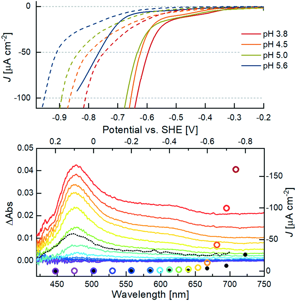 | ||
| Fig. 5 Top: LSV measurements of 6@m-TiO2 (solid lines) at different pH values. Dashed lines correspond to bare TiO2 at the respective potential. Conditions: working electrode in aq. sat. KClO4, buffered by 50 mM acetic acid, titrated with NaOH to the respective pH. Measurements were carried out with a scan rate of 1 mV s−1, Ag/AgCl reference electrode and a Pt wire as counter electrode. Bottom: CA measurements with monitoring of the potential-dependent Vis-absorption (left and bottom axis) of 6@m-TiO2. The color code corresponds to the applied potential vs. SHE starting from 0.2 V (purple) to −0.75 V (red) in 50 mV steps. The black dotted line corresponds to the transient spectrum of the photocatalytic system in solution (Fig. 2, bottom), after 100 μs. The current density J at a given potential (right and upper axes) is given in colored circles (sample) and black dots (bare m-TiO2 electrode), respectively. | ||
In situ spectroelectrochemistry, a suitable tool previously used to analyse the electronic structure of porphyrins,54–57 was used for studying the oxidation states of the anchored catalyst. The Vis-spectra shown in the bottom of Fig. 5 were taken during CA measurements after stabilization of the current density J, in response to the applied constant potential V. The current density is marked by the coloured circles in Fig. 5. The black dots correspond to J of the blank sample at the same potential. The beginning of the exponential increase of J from a potential of −0.60 V vs. SHE at pH 5 is in line with the VH2 determined by the aforementioned linear extrapolation evaluation of the LSV measurement. The maximum of the positive ΔAbs signal at 475 nm agrees well with the observed transient spectra of the singly reduced WRC under photocatalytic conditions (black dotted spectrum in Fig. 5, bottom), and both can thus be certainly attributed to a CoI species. Notably, the CoI absorption appears from a potential of −0.35 V vs. SHE, 250 mV before catalysis sets in. Mechanistically, this is in line with the observed pH dependency of VH2: reduction of the ground state CoII gives the CoI species observed at 475 nm and −0.35 V vs. SHE, but H2 evolution only proceeds after further reduction to a formal Co0, followed by protonation.
Long-term stability
Analogously to the previous experiment, the catalyst was adsorbed on the m-TiO2 coated FTO glass (6@m-TiO2). The working electrode was immersed in the buffered electrolyte (pH 5) and the solution degassed until no air was detected by GC in the out-coming gas stream. Several CV cycles between +0.25 and −0.4 V vs. SHE were conducted to fill unoccupied surface states in order to minimize non-faradaic current in the subsequent experiment. The potential was set to −0.65 V vs. SHE and the current density J measured over time. The data were corrected for the current contribution of the respective blank experiments with the catalytically inactive zinc-complex 11 adsorbed on the working electrode (11@m-TiO2).As shown in Fig. 6, electrolysis starts off after a first current spike with a current density of ≈70 μA cm−2, decreasing to half of its original value within the first 24 hours. As the comparison with the zinc complex 11@m-TiO2 shows, the faradaic current exclusively stems from the adsorbed catalyst (Fig. S17†). After this initial decrease, charge transfer proceeds over the period of approximately 2 days. Simultaneously measured H2 evolution traces (Fig. 6, blue trace) confirm the current to be faradaic and converted by 95% to H2 (see Fig. S18†), stressing the efficient proton reduction by 6@m-TiO2. The initial increase of the H2 formation rate arises from the response time of the setup, after which the exponential decay of the current trace is well reflected in the H2 evolution profile. Dihydrogen formation is observed over a period of 2 days, before catalysis ceases after formation of (90 ± 4) μmol H2, corresponding to (535500 ± 25500) TONs at a maximal rate of (8.6 ± 0.3) H2 WRC−1 s−1. The immobilized catalyst was confirmed as the only catalytically active cobalt-species by a separate CA-experiment, including bare TiO2 as working electrode and WRC 8 (lacking the anchoring groups) dissolved in the electrolyte. Under equivalent conditions to the previous experiment, no H2-formation was observed confirming 6 to be only active if covalently bound to the surface (see Fig. S19†).
 | ||
| Fig. 6 Current (red line, left axes) and H2 formation rate (blue line, right axes) traces of CA measurement at −0.65 V vs. SHE. Conditions: 6@m-TiO2 as working electrode in KClO4 (aq. sat.), buffered with 50 mM acetic acid at pH 5. Ag/AgCl served as reference and a Pt wire as counter electrode. The system was constantly purged with aq. sat. argon and the out coming gas mixture frequently analyzed by in-line GC for H2-formation. | ||
Notably, traces of evolved H2 could be measured at a potential as early as −0.6 V vs. SHE in a separate experiment (see Fig. S20†), confirming the onset potential as predicted by the linear extrapolation method of the LSV measurements.
Comparison of XPS spectra before and after electrocatalysis corroborates the binding stability of 6@m-TiO2 under catalytic conditions. The Co 2p3/2 core level spectrum of freshly adsorbed 6@m-TiO2 shows three distinct signals (Fig. 7, top). The weak satellite at 789 eV is caused by spin-exchange interactions of the photoelectron and an unpaired 3d-electron of Co(II),58 corresponding to the oxidation state of 6, as is used for the loading solution. Apart from the satellite, the spectrum can be fitted with 2 Gaussians. According to DFT studies by Iannuzzi et al., cobalt–pyrpyrins adsorb on TiO2 (110) with different geometries, either with cobalt located above Ti4+ or coordinating to O2−, the latter one exhibiting a much larger cobalt-surface interaction.59 We attribute the two peaks to the different adsorption modes: the absorption at 779.9 eV is in accordance to previous XPS studies on cobalt–pyrphyrin reported by Osterwalder et al., with cobalt located on Ti4+ (780.5 eV (ref. 60)). The peak at 783.5 eV is attributed to the Co–O binding site with higher binding energy. The P 2p absorption shows one single peak at 134.3 eV, indicating identical covalent binding of all phosphonate anchoring groups.
 | ||
| Fig. 7 XPS data and fits of Co 2p3/2 (left column) and P 2p core levels (right column) of 6@m-TiO2 before (top row) and after 3 days (bottom row) of electrolysis. Residuals of the fitted Gaussians are given in the same scale as the data. | ||
In a second experiment, the electrode was first subjected to electrolysis for 2.5 days and then investigated by XPS as shown in Fig. 7, bottom. The satellite at 789 eV is no longer present, as the catalyst was oxidized to CoIII by backing the applied potential to +0.25 V vs. SHE (0 V vs. Ag/AgCl) at the end of each electrolysis. Apart from that, Co 2p3/2 and P 2p spectra of the used electrode confirmed the catalyst in unchanged configuration still bound to the surface. Both binding modes, Co–Ti4+ and Co–O, are still observed after electrolysis. Quantification of the desorbed amount of catalyst was conducted by ICP-MS analysis of the electrolyte after the same period of time. A cobalt concentration of (40.2 ± 1.7) pmol ml−1 in 31.5 ml electrolyte confirmed a desorbed cobalt amount of (9.7 ± 1.5) % after 2.5 days of electrolysis. The moderate desorption compared to photocatalysis is attributed to the reduced amount of co-adsorbing species (50 mM acetic acid in elelctrocatalysis, vs. 0.1 M of both ascorbic acid and TCEP in photocatalysis).
From the unchanged XP spectra before and after electro-catalysis, we exclude the formation of cobalt nanoparticles (Co-NPs), an issue which was addressed by Artero and co-workers.61In situ generated Co-NPs from cobalt diimine or dioxime WRCs, were shown to bind stably to FTO under reductive conditions (−0.6 V vs. Ag/AgCl at pH 7) and be responsible for high faradaic yields in H2-generation. This catalytically active film is readily dissolved in the electrolyte at more positive potentials and therefore hard to exclude by electrode rinse-tests.62 In the present experiment only a fraction of the cobalt was detected in the electrolyte after catalysis (ICP-MS) and the configuration of the remaining WRC on the electrode seems unchanged, thus we attribute the H2-evolution catalysis to the molecular WRC 6@m-TiO2.
This long term stability under catalytic conditions is remarkable, however, the data do not conclusively explain the decrease of catalytic current and H2-formation. As ca. 90% of the catalyst is still bound to the surface after 2.5 days, an increasing fraction over time must lose its catalytic activity. This could either arise from deactivation of the catalyst in a way that it retains an in-differentiable XPS spectrum from the original structure (e.g. by partial hydrogenation of the pyridyl units). A more probable explanation is decreasing conductivity of the FTO/TiO2 support over time. Among others, Geiger et al. reported dissolution of SnO2 under acidic, reductive conditions according to SnO2 + H+ + 2e− → Sn2+ + 2H2O (+0.07 V vs. SHE), leading to increasing ohmic losses, thus decreased conductivity.63,64 ICP-MS analysis confirmed trace amounts of dissolved tin in the electrolyte after 2.5 days of electrolysis. We assume that H2O diffuses through the mesoporous TiO2-structure, favouring reductive Sn-dissolution over time. Section wise “cut-off” of substrate holding immobilized WRC from the circuit might reconcile the stable binding with decreasing catalytic activity. Experimental evidence is provided by CA experiments with alternating potential between −0.65 V and +0.2 V vs. SHE with a 1 hour frequency. The “regeneration phase” at +0.2 V (0 V vs. Ag/AgCl) allowed to re-oxidize partly reduced SnO2 and delay the destructive reduction of the conductive layer. As evident from Fig. S21,† electrolysis restarts after each equilibration phase and H2-evolution follows the same trend. This procedure can be repeated for more than 10 days, meaning over 5 days of active electrocatalysis. This confirms catalyst-desorption not to be the stability limiting factor of electrocatalysis but reductive substrate dissolution.
Experimental
General
All chemicals used were of reagent grade, and unless otherwise stated, reactions were carried out under N2 atmosphere. Solvents were of p.a. grade, THF and diethyl ether were dried over Na/benzophenone. Water for reactions, extractions and catalytic experiments was deionized and doubly distilled prior to usage. Reaction controls were carried out by HPLC (VWR Hitachi LaChrome; Column: Reproshell, C18, 2.6 μm, operated in an oven L-2350 at 40 °C and a DA detector L-2450. Eluent: H2O/MeOH/TFA, gradient starting with 10% MeOH, 0.1% TFA in H2O to pure MeOH within 11 min, 1 ml min−1). NMR measurements were carried out on an AV3-400 Bruker NMR spectrometer at 25 °C.Synthesis
:1 mixture of ACN/THF lead to an approximately 95% pure product, which could be used without further purification.
Conclusions
The synthesis of the new, macrocyclic cobalt-polypyridyl WRC 6 featuring two cis-oriented phosphonic acid anchoring groups enables the application of a molecular WRC in a heterogeneous, photo- and electrocatalytic system. The newly synthesized WRC 6 binds stably to TiO2 in the acidic to slightly basic pH region, and can be adsorbed on TiO2 with a loading density of 9.4 × 10⁻² nmol cm−2. Photocatalytic investigations revealed that the anchoring groups do not affect the catalytic activity in solution, and ET from the bulk solution to the surface occurs equally fast as in a fully homogeneous system. As shown by electrocatalytic investigations, the onset potential lies at 0.6 V vs. SHE, 250 mV after the first cobalt reduction. Finally, CA measurements imply the remarkable long-term stability of the catalyst on the surface under electrocatalytic conditions. At a potential of −0.65 V vs. SHE (pH 5), H2 formed during a period of 2.5 days, with a faradaic efficiency of 95% and TON of (535500 ± 25500) H2 Co−1. XPS studies of the electrode before and after electrolysis in combination with ICP-MS analysis of the electrolyte confirmed stable binding of the WRC under catalytic conditions and quantified the desorbed amount to (9.7 ± 1.5) %.
These results encourage to modify well established surface materials with molecular catalytic sites in order to reduce onset potentials and to increase the catalytic rates, both final goals in view of photocatalytic water splitting being a large scale applicable and sustainable energy source and storage.
Conflicts of interest
The authors declare no conflict of interest.Acknowledgements
Financial support from the Swiss national Science Foundation SNSF Sinergia project CRSII2 160801/2 and from the University Research Priority Program (URPP) Light to Chemical Energy Conversion “LightChEC” is gratefully acknowledged. J. B. and J. O. acknowledge financial support from the Swiss National Science Foundation through the NCCR MUST.References
- A. Züttel, A. Remhof, A. Borgschulte and O. Friedrichs, Philos. Trans. R. Soc., A, 2010, 368, 3329–3342 CrossRef PubMed.
- S. Berardi, S. Drouet, L. Francàs, C. Gimbert-Suriñach, M. Guttentag, C. Richmond, T. Stoll and A. Llobet, Chem. Soc. Rev., 2014, 43, 7501–7519 RSC.
- R. M. Evans, E. J. Brooke, S. A. M. Wehlin, E. Nomeratskaia, F. Sargent, S. B. Carr, S. E. V. Phillips and F. A. Armstrong, Nat. Chem. Biol., 2016, 12, 46–52 CrossRef CAS PubMed.
- M. Rakowski DuBois and D. L. DuBois, Chem. Soc. Rev., 2009, 38, 62–72 RSC.
- T. Hisatomi, J. Kubota and K. Domen, Chem. Soc. Rev., 2014, 43, 7520–7535 RSC.
- A. Kudo and Y. Miseki, Chem. Soc. Rev., 2009, 38, 253–278 RSC.
- F. Gloaguen and T. B. Rauchfuss, Chem. Soc. Rev., 2009, 38, 100–108 RSC.
- Z. Han, L. Shen, W. W. Brennessel, P. L. Holland and R. Eisenberg, J. Am. Chem. Soc., 2013, 135, 14659–14669 CrossRef CAS PubMed.
- S. Losse, J. G. Vos and S. Rau, Coord. Chem. Rev., 2010, 254, 2492–2504 CrossRef CAS.
- V. Artero, M. Chavarot-Kerlidou and M. Fontecave, Angew. Chem., Int. Ed., 2011, 50, 7238–7266 CrossRef CAS PubMed.
- W. T. Eckenhoff and R. Eisenberg, Dalton Trans., 2012, 41, 13004–13021 RSC.
- S. Schnidrig, C. Bachmann, P. Müller, N. Weder, B. Spingler, E. Joliat-Wick, M. Mosberger, J. Windisch, R. Alberto and B. Probst, ChemSusChem, 2017, 10, 4570–4580 CrossRef CAS PubMed.
- N. Queyriaux, R. T. Jane, J. Massin, V. Artero and M. Chavarot-Kerlidou, Coord. Chem. Rev., 2015, 304, 3–19 CrossRef PubMed.
- H. I. Karunadasa, C. J. Chang and J. R. Long, Nature, 2010, 464, 1329–1333 CrossRef CAS PubMed.
- M. A. Gross, A. Reynal, J. R. Durrant and E. Reisner, J. Am. Chem. Soc., 2014, 136, 356–366 CrossRef CAS PubMed.
- V. S. Thoi, Y. J. Sun, J. R. Long and C. J. Chang, Chem. Soc. Rev., 2013, 42, 2388–2400 RSC.
- M. Wang, L. Chen and L. C. Sun, Energy Environ. Sci., 2012, 5, 6763–6778 RSC.
- W. T. Eckenhoff, Coord. Chem. Rev., 2018, 373, 295–316 CrossRef CAS.
- S. Fukuzumi, Y. M. Lee and W. Nam, Coord. Chem. Rev., 2018, 355, 54–73 CrossRef CAS.
- K. E. Dalle, J. Warnan, J. J. Leung, B. Reuillard, I. S. Karmel and E. Reisner, Chem. Rev., 2019, 119, 2752–2875 CrossRef CAS PubMed.
- M. L. Helm, M. P. Stewart, R. M. Bullock, M. R. DuBois and D. L. DuBois, Science, 2011, 333, 863–866 CrossRef CAS PubMed.
- E. Joliat-Wick, N. Weder, D. Klose, C. Bachmann, B. Spingler, B. Probst and R. Alberto, Inorg. Chem., 2018, 57, 1651–1655 CrossRef CAS PubMed.
- E. Joliat, S. Schnidrig, B. Probst, C. Bachmann, B. Spingler, K. K. Baldridge, F. von Rohr, A. Schilling and R. Alberto, Dalton Trans., 2016, 45, 1737–1745 RSC.
- T. Morikawa, S. Sato, K. Sekizawa, T. Arai and M. T. Suzuki, ChemSusChem, 2019, 12, 1807–1824 CrossRef CAS PubMed.
- B. Zhang and L. Sun, Chem. Soc. Rev., 2019, 48, 2216–2264 RSC.
- C. D. Windle, H. Kumagai, M. Higashi, R. Brisse, S. Bold, B. Jousselme, M. Chavarot-Kerlidou, K. Maeda, R. Abe, O. Ishitani and V. Artero, J. Am. Chem. Soc., 2019, 141, 9593–9602 CrossRef CAS PubMed.
- T. E. Rosser, M. A. Gross, Y.-H. Lai and E. Reisner, Chem. Sci., 2016, 7, 4024–4035 RSC.
- F. Li, K. Fan, B. Xu, E. Gabrielsson, Q. Daniel, L. Li and L. Sun, J. Am. Chem. Soc., 2015, 137, 9153–9159 CrossRef CAS PubMed.
- C. Bachmann, B. Probst, M. Oberholzer, T. Fox and R. Alberto, Chem. Sci., 2016, 7, 436–445 RSC.
- A. Paracchino, V. Laporte, K. Sivula, M. Grätzel and E. Thimsen, Nat. Mater., 2011, 10, 456–461 CrossRef CAS PubMed.
- S. D. Tilley, M. Schreier, J. Azevedo, M. Stefik and M. Grätzel, Adv. Funct. Mater., 2014, 24, 303–311 CrossRef CAS.
- L. Tong, R. Zong and R. P. Thummel, J. Am. Chem. Soc., 2014, 136, 4881–4884 CrossRef CAS PubMed.
- A. Rodenberg, M. Orazietti, B. Probst, C. Bachmann, R. Alberto, K. K. Baldridge and P. Hamm, Inorg. Chem., 2015, 54, 646–657 CrossRef CAS PubMed.
- P. Müller and K. Brettel, Photochem. Photobiol. Sci., 2012, 11, 632–636 RSC.
- A. Rodenberg, M. Orazietti, M. Mosberger, C. Bachmann, B. Probst, R. Alberto and P. Hamm, ChemPhysChem, 2016, 17, 1321–1328 CrossRef CAS PubMed.
- F. Lakadamyali, M. Kato and E. Reisner, Faraday Discuss., 2012, 155, 191–205 RSC.
- R. S. Khnayzer, V. S. Thoi, M. Nippe, A. E. King, J. W. Jurss, K. A. El Roz, J. R. Long, C. J. Chang and F. N. Castellano, Energy Environ. Sci., 2014, 7, 1477–1488 RSC.
- Y. Huogen, H. Irie and K. Hashimoto, J. Am. Chem. Soc., 2010, 132, 6898–6899 CrossRef PubMed.
- M. Grätzel, Nature, 2001, 414, 338–344 CrossRef PubMed.
- D. W. Wakerley and E. Reisner, Phys. Chem. Chem. Phys., 2014, 16, 5739–5746 RSC.
- D. Dolui, S. Khandelwal, A. Shaik, D. Gaat, V. Thiruvenkatam and A. Dutta, ACS Catal., 2019, 9, 10115–10125 CrossRef CAS.
- R. H. Schuler, Radiat. Res., 1977, 69, 417–433 CrossRef CAS PubMed.
- G. M. Brown, B. S. Brunschwig, C. Creutz, J. F. Endicott and N. Sutin, J. Am. Chem. Soc., 1979, 101, 1298–1300 CrossRef CAS.
- M. Natali, A. Luisa, E. Iengo and F. Scandola, Chem. Commun., 2014, 50, 1842–1844 RSC.
- C. Bachmann, B. Probst, M. Guttentag and R. Alberto, Chem. Commun., 2014, 50, 6737–6739 RSC.
- C. Creutz, N. Sutin and B. S. Brunschwig, J. Am. Chem. Soc., 1979, 101, 1297–1298 CrossRef CAS.
- M. R. Hoffmann, S. T. Martin, W. Choi and D. W. Bahnemann, Chem. Rev., 1995, 95, 69–95 CrossRef CAS.
- L. Kohler, J. Niklas, R. C. Johnson, M. Zeller, O. G. Poluektov and K. L. Mulfort, Inorg. Chem., 2019, 58, 1697–1709 CrossRef CAS PubMed.
- C. V. Krishnan, C. Creutz, D. Mahajan, H. A. Schwarz and N. Sutin, Isr. J. Chem., 1982, 22, 98–106 CrossRef CAS.
- G. M. Jacobsen, J. Y. Yang, B. Twamley, A. D. Wilson, R. M. Bullock, M. Rakowski DuBois and D. L. DuBois, Energy Environ. Sci., 2008, 1, 167–174 RSC.
- A. Dutta, A. M. Appel and W. J. Shaw, Nat. Rev. Chem., 2018, 2, 244–252 CrossRef CAS.
- A. A. Marti and J. L. Colon, Inorg. Chem., 2010, 49, 7298–7303 CrossRef CAS PubMed.
- V. Bajic, B. Spremo-Potparevic, L. Zivkovic, A. Cabarkapa, J. Kotur-Stevuljevic, E. Isenovic, D. Sredojevic, I. Vukoje, V. Lazic, S. P. Ahrenkiel and J. M. Nedeljkovic, Colloids Surf., B, 2017, 155, 323–331 CrossRef CAS PubMed.
- N. Kornienko, Y. Zhao, C. S. Kley, C. Zhu, D. Kim, S. Lin, C. J. Chang, O. M. Yaghi and P. Yang, J. Am. Chem. Soc., 2015, 137, 14129–14135 CrossRef CAS PubMed.
- N. M. Muresan, J. Willkomm, D. Mersch, Y. Vaynzof and E. Reisner, Angew. Chem., Int. Ed., 2012, 51, 12749–12753 CrossRef CAS PubMed.
- S. R. Ahrenholtz, C. C. Epley and A. J. Morris, J. Am. Chem. Soc., 2014, 136, 2464–2472 CrossRef CAS PubMed.
- T. E. Rosser and E. Reisner, ACS Catal., 2017, 7, 3131–3141 CrossRef CAS.
- Y. G. Borod'ko, S. I. Vetchinkin, S. L. Zimont, I. N. Ivleva and Y. M. Shul'ga, Chem. Phys. Lett., 1976, 42, 264–267 CrossRef.
- S. Luber, M. Iannuzzi and J. Hutter, Phys. Chem. Chem. Phys., 2015, 17, 22846–22854 RSC.
- M. Graf, G. Mette, D. Leuenberger, Y. Gurdal, M. Iannuuzzi, W.-D. Zabka, S. Schnidrig, B. Probst, J. Hutter, R. Alberto and J. Osterwalder, Nanoscale, 2017, 9, 8756–8763 RSC.
- N. Kaeffer, A. Morozan, J. Fize, E. Martinez, L. Guetaz and V. Artero, ACS Catal., 2016, 6, 3727–3737 CrossRef CAS.
- S. Cobo, J. Heidkamp, P.-A. Jacques, J. Fize, V. Fourmond, L. Guitaz, B. Jousselme, V. Ivanova, H. Dau, S. Palacin, M. Fontecave and V. Artero, Nat. Mater., 2012, 11, 802–807 CrossRef CAS PubMed.
- S. Geiger, O. Kasian, A. M. Mingers, K. J. J. Mayrhofer and S. Cherevko, Sci. Rep., 2017, 7, 4595–4601 CrossRef PubMed.
- A. Korjenic and K. S. Raja, J. Electrochem. Soc., 2019, 166, 169–184 CrossRef.
- L.-X. Gao, X.-L. Bai, X.-D. Liu, M. Wang and C.-Q. Kang, Synthesis, 2005, 2005, 458–464 CrossRef.
Footnote |
| † Electronic supplementary information (ESI) available. CCDC 1958070–1958072. For ESI and crystallographic data in CIF or other electronic format see DOI: 10.1039/d0cy00330a |
| This journal is © The Royal Society of Chemistry 2020 |