 Open Access Article
Development of catalysts for ammonia synthesis based on metal phthalocyanine materials†
Natalia
Morlanés
*a,
Walid
Almaksoud
a,
Rohit K.
Rai
a,
Samy
Ould-Chikh
 a,
Mohammed M.
Ali
b,
Balamurugan
Vidjayacoumar
b,
Bedour E.
Al-Sabban
b,
Khalid
Albahily
b and
Jean-Marie
Basset
 *a
*a
aKAUST Catalysis Center and Division of Physical Sciences and Engineering, King Abdullah University of Science and Technology (KAUST), Thuwal, 23955-6900, Kingdom of Saudi Arabia. E-mail: jeanmarie.basset@kaust.edu.sa; natalia.morlanes@kaust.edu.sa
bSABIC Corporate Research and Development Center at KAUST, Saudi Basic Industries Corporation, Thuwal 23955, Kingdom of Saudi Arabia
First published on 16th December 2019
Abstract
Highly efficient and very stable iron and/or cobalt-based catalysts for the ammonia synthesis reaction were synthesized by one-step pyrolysis of metal phthalocyanine precursors. The presence of alkaline earth or alkali metals is found to be essential for accelerating the reaction rate for the ammonia synthesis process. When promoted by alkali metals, the catalysts show a 3-fold increase in their catalytic performance (at 400 °C and 0.1–7 MPa) compared to a commercial benchmark iron-based catalyst, widely used for the Haber–Bosch process. TEM images reveal the local structure of the catalysts obtained upon pyrolysis of the metal phthalocyanine precursor, with metal nanoparticles (5–50 nm) confined in a nitrogen-doped carbon mesoporous matrix, where the alkali metal promoters are located on the top of the iron nanoparticles but also on the carbon support. Finally, kinetic analysis shows a lower activation energy for the Fe phthalocyanine-derived catalyst (42 kJ mol−1) versus 70 kJ mol−1 reported for the iron-benchmark catalyst. Furthermore, this kinetic analysis suggests that the rate-determining step shifts from nitrogen activation to NHx formation, which only few catalysts have achieved.
Introduction
Ammonia synthesis is the key technology for the production of synthetic fertilizers and nitrogen-containing chemicals.1,2 The negative environmental impact of the Haber–Bosch process is enormous, since 3% of the global CO2 emissions into the atmosphere are related to industrial, large-scale NH3 synthesis3 (1.9 metric tons of fossil CO2 are released per metric ton of ammonia produced).4Considering the very harsh operating conditions of the Haber–Bosch process (350–525 °C and 10–30 MPa) with an iron-based commercial catalyst, the process is responsible for roughly 1% of the annual global energy consumption.5–7 Consequently, it is highly desirable to develop more efficient and stable catalysts.
Theoretical calculations have revealed that the activation barrier for nitrogen dissociation and binding energy are scaling with each other, with a linear energy relation.8 Thus, for conventional catalyst formulations, it has not yet been possible to obtain a situation where the barrier is very low, and the binding energies of the relevant intermediates are low. Nevertheless, it might be possible to find a reaction pathway where the barrier for the initial activation of dinitrogen is decreased.8 This could lead to much more active catalysts operating at lower temperatures, and the reaction rates could be orders of magnitude higher than what are seen today.
The route to design more active catalysts requires a step out from that of the conventional catalyst, in order to develop new catalytic systems with an optimized balance between activation and bonding, as observed in homogeneous catalysis.3 An example is by designing heterogeneous analogs of known homogeneous nitrogen-fixing systems based on two main components: a transition metal compound needed for activating dinitrogen and a sufficiently strong reducing agent serving as a source of electrons for reducing activated N2 molecules.9–11 This could be achieved by creating interfaces between two different types of sites or introducing confined active sites like those found in carbon-based materials.3
Nowadays, one-step pyrolysis of metal–organic compounds12 has recently emerged as a new strategy and facile method for the preparation of metal nanoparticles embedded in carbon nanostructures. Metal clusters are thus confined in the cavities created by the decomposition of organic compounds.13–15 Different from the traditional synthetic strategies, the solid-state pyrolysis of metal–organic compounds undergoes two main pathways: thermal reduction of metal atoms and carbonization of organic molecules, which generate metal/heteroatom-doped carbon composites.16–18
Inspired by this novel and facile synthetic strategy, we report here efficient iron and/or cobalt-based catalysts for ammonia synthesis. This is achieved by a one-step pyrolysis of iron and/or cobalt phthalocyanine precursors (FePc and/or CoPc) (Scheme 1). The resulting materials, iron and/or cobalt nanoparticles supported on nitrogen-doped carbon composites, exhibit catalytic activity for ammonia synthesis with better performances than conventional catalysts and with long-term stability. Commercial phthalocyanines are widely used industrially with a worldwide annual production of >80![[thin space (1/6-em)]](https://www.rsc.org/images/entities/char_2009.gif) 000 ton from cheap phthalonitrile precursors.19
000 ton from cheap phthalonitrile precursors.19
Results and discussion
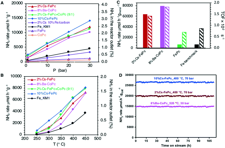
Different iron and/or cobalt-based catalysts were prepared by one-step pyrolysis under nitrogen at 735 °C of commercially available metal phthalocyanines, FePc, CoPc and mixture FePc + CoPc, as detailed in the ESI.† After the pyrolysis, alkali metals were incorporated by impregnation. Activation under H2/N2 atmosphere of the resulting materials was conducted prior to catalytic activity measurements.All the catalysts were tested for the ammonia synthesis reaction in a fixed-bed flow reactor as described in the ESI.† The catalytic activity and stability of the materials explored here are shown in Fig. 1 and compared with the performance of an iron benchmark catalyst (doubly promoted iron catalyst, KM1) for the Haber-–Bosch process.20–22
Fig. 1A and B show the pressure and temperature dependence of the catalytic activity, respectively. As clearly visible, all of the catalysts obtained from phthalocyanine precursors, when promoted by alkali metals (2%Cs–FePc, 8%Ba–CoPc, 2%Cs–FeCoPc and 10%Cs–FePc), were very efficient in the ammonia synthesis reaction and led to a higher activity than the commercial catalyst used as a benchmark. When promoted by alkali metals, the 10%Cs–FePc catalyst showed a 3-fold increase in the catalytic performance (at 400 °C and 0.1–3 MPa) compared to the commercial benchmark iron-based catalyst.
The catalyst 10%Cs–FePc showed an NH3 synthesis rate of 14![[thin space (1/6-em)]](https://www.rsc.org/images/entities/char_2009.gif) 000 μmol g−1 h−1 at 400 °C and 3 MPa, with a similar catalytic performance to cesium-promoted Co3Mo3N,22 and is reported to be not only better than the iron-based catalyst but also better than the commercial graphite supported ruthenium.23,24
000 μmol g−1 h−1 at 400 °C and 3 MPa, with a similar catalytic performance to cesium-promoted Co3Mo3N,22 and is reported to be not only better than the iron-based catalyst but also better than the commercial graphite supported ruthenium.23,24
The reaction rate over these catalysts shows an approximately linear response to the pressure increase (Fig. 1A). For 2%Cs–FePc, the rate underwent a near sevenfold rise to 20![[thin space (1/6-em)]](https://www.rsc.org/images/entities/char_2009.gif) 000 μmol gcat−1 h−1 when the reaction pressure was increased from 1 to 7 MPa at 400 °C (Fig. S3 in the ESI†).
000 μmol gcat−1 h−1 when the reaction pressure was increased from 1 to 7 MPa at 400 °C (Fig. S3 in the ESI†).
When the catalytic performance is evaluated with the specific activity (Fig. 1C), the reaction rate per gram of metal over the 2%Cs–FePc and 8%Ba–CoPc catalysts is about 10 times that of the commercial benchmark catalyst. The activity was also evaluated per the number of active surface sites (as detailed in the ESI†); for the 2%Cs–FePc catalyst, the TOF is 1.51 × 10⁻² s−1, almost 2 times faster than that of the Fe-based commercial catalyst (0.85 × 10⁻² s−1).
The crucial role of cesium (for Fe) or barium (for Co) in these systems is illustrated by the fact that in the absence of the alkali metal, the reaction rate dramatically decreases (Fig. 1A). The alkali promotion is commonly assumed to proceed via electron transfer from an alkali metal to the Fe surface.4,25,26 As a result of the presence of alkali or alkaline earth metals, the barrier for nitrogen dissociation (a commonly accepted rate-limiting step in ammonia synthesis) is decreased. Furthermore, also all NHx species, including adsorbed NH3 molecules, would be destabilized resulting in more free sites on the surface, thus, increasing the catalytic activity.27,28
In order to confirm that the use of the phthalocyanine template is absolutely necessary to attain the most active structure for this process and to boost the catalyst performance, a control experiment was performed using a sample of iron/alkali metal supported on carbon (2%Cs–10%Fe/carbon) prepared by an impregnation method according to the previously reported procedure.29 The catalyst derived from phthalocyanine (Cs–FePc) exhibited much better activity for ammonia synthesis (Fig. 1A), compared to that of the catalysts prepared by the traditional impregnation method, corroborating the advantage of using phthalocyanines to obtain highly active catalysts.
The catalyst stability under reaction conditions appeared satisfactory as shown in Fig. 1D. No deactivation phenomenon was observed during the long-term stability test performed for 100 h with 2%Cs–FePc and 8%Ba–CoPc. The ammonia synthesis rate remained perfectly constant under several reaction conditions in the range of 400–520 °C and 3–7 MPa.
Usually, for carbon-based catalysts, the resistance of the system to the methanation of the support under ammonia synthesis conditions is an important issue.30 Early studies have demonstrated, however, that both iron and cobalt poorly catalyze the hydrogenation of the carbon support (whereas the methanation of the substrate material starts at 480 °C for Ru/C and Ni/C, and it starts between 800–850 °C for Co/C and Fe/C).31 This is far above the temperature for NH3 synthesis. Under the reaction conditions explored here, 400 °C and 1–7 MPa, methane was not detected either by mass spectrometry or with GC instruments connected online to a reactor outlet. For similar materials, methanation was not observed until 800 °C.32
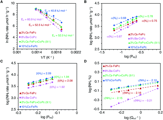
Finally, we analyzed the kinetics with these phthalocyanine-derived catalysts, and the results are shown in Fig. 2. The kinetic parameters were obtained for 2%Cs–FePc, 8%Ba–CoPc, 2%Cs–FeCoPc and 10%Cs–FePc (Table 1) and can be compared with the values reported for selected catalysts from the literature (Table S1 in the ESI†). Apparent activation energies were calculated from the Arrhenius plots (Fig. 2A). The smaller value of the apparent activation energy (42 kJ mol−1) for the 10%Cs–FePc catalyst, compared to the value for the benchmark catalyst (70 kJ mol−1), provides evidence that N2 dissociation over this catalyst is favored (dissociative mechanism). This value is close to the one observed for other catalysts, in which the formation of NHx species was claimed as the rate-limiting step (Table S1 in the ESI†)33 The difference in the catalytic performance between the FePc and CoPc catalysts (Fig. 1A) is matching with the different values observed for the apparent activation energies, 41.9 versus 60.9 kJ mol−1, for the FePc and CoPc catalysts respectively. This can be explained by the difference between the nitrogen adsorption energies in Fe and Co metals.7
| Catalysts | E a (kJ mol−1) | N2 order (α) | H2 order (β) | NH3 order (γ) |
|---|---|---|---|---|
| 2%Cs–FePc | 52.5 | 0.75 | 2.08 | −2.16 |
| 8%Ba–CoPc | 60.9 | 0.87 | 1.92 | −0.21 |
| 2%Cs–FePc + CoPc | 52.0 | 0.78 | 1.94 | −2.15 |
| 10%Cs–FePc | 41.9 | 0.68 | 2.10 | −2.10 |
| Fe-Benchmark cat. | 70 | 0.9 | 2.2 | −1.5 |
The N2 reaction orders for the explored catalysts are shown in Fig. 2B and Table 1. The N2 reaction orders for the conventional heterogeneous catalysts are varying from 0.8 to 1.0. (Table S1 in the ESI†). A slight decrease in the N2 reaction order with increasing cesium loading (10%Cs–FePc catalyst) suggests that nitrogen dissociation is faster,33 which is in agreement with the recently reported catalysts.34,35
The reaction order with respect to H2 is around 2 (Fig. 2C and Table 1) since H2 dissociates on the Fe surface. A similar value is reported for the commercial benchmark iron-based catalyst.21,28
The reaction order with respect to NH3 is around −2 for the iron-based catalysts explored here (Fig. 2D and Table 1). This observation suggests that ammonia competes with H2 for the same Fe sites, and the NHx species cover the active surface more densely than H and N adatoms.36 This is an important issue which is also affecting the Fe-based commercial catalyst, bimetallic Co3Mo3N and most of the catalysts reported (Table S1 in the ESI†).
In high contrast with Fe based systems, for the cobalt-based catalyst (8%Ba–CoPc), the most significant observation is the reaction order with respect to ammonia, −0.2, suggesting that the Co-based catalysts are much less poisoned by ammonia, which is in agreement with other cobalt catalysts reported.28 For that reason, the ammonia synthesis rate is less affected with Co than with Fe in terms of the changes in the space velocity due to the differences in the ammonia concentration levels (Fig. S4 in the ESI†). This is essential for the industrial practice, where the low inhibition of the reaction rate by the ammonia product is an essential factor in the catalyst usefulness.
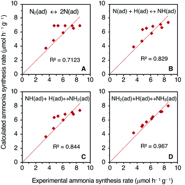
The rate-determining step (RDS) for the NH3 synthesis over the 10%Cs–FePc catalyst was further examined by comparing the experimental reaction rates and calculated rates. The rate equations were established based on the Langmuir–Hinshelwood mechanism (ESI†).37 The rate (eqn (9)–(12) in the ESI†) were deduced by assuming the dissociation of N2 or formation of NH, NH2 or NH3 as the RDS, respectively.33,36 To identify the RDS for the ammonia synthesis reaction, the derived equations were then fitted by a least-squares method to the set of experimental rates obtained for different reaction gas compositions. The best fitting of the modeled rates to the experimental rates is shown in Fig. 3. The fitting is not so good when the activation of N2 is supposed to be the RDS. In contrast, when the formation of NH, NH2 and NH3 are assumed to be the RDS, the fitting improved significantly; the NH3 formation rate reveals the highest R2 value of 0.96 in this case (Fig. 3D). These fittings indicate that the RDS for ammonia synthesis over these catalytic systems derived from metal phthalocyanines could be any of the formation steps of the NHx species rather than the N2 dissociation step, only achieved by few catalysts in the literature.33,36,38
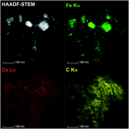
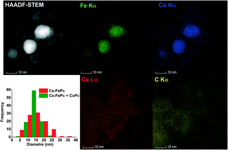
The local structure of the 10%Cs–FePc and 2%Cs–FePc + CoPc catalysts was evaluated using high-angle annular dark-field scanning transmission electron microscopy (HAADF-STEM) and energy-dispersive X-ray spectroscopy (EDX). The representative TEM images in Fig. 4 and 5 of the materials synthesized by the pyrolysis of the different phthalocyanine precursors were collected after the NH3 synthesis reaction. As shown in Fig. 4, small-sized Fe and Fe–Co nanoparticles are highly dispersed onto the nitrogen-doped carbon support material; as previously observed for the phthalocyanines after the pyrolysis process, and widely reported in the literature.12–15 The size of the metal particles is mainly distributed in the range of 5–50 nm, with a particle size distribution being generally quite broad, as observed for both 10%Cs–FePc (16 nm average particle size in number) and 2%Cs–FePc + CoPc (13 nm average particle size in number). The catalysts were characterized by energy-dispersive X-ray (EDX) analysis of Fe, Co, Cs and C. The alkali metal introduced by impregnation, cesium, is located on the top of the iron nanoparticles but also on the support in both the samples. The Cs loading in the catalyst 2%Cs–FePc after the reaction was around 1.8 ± 0.8 wt% according to EDX analysis. The nitrogen content in the range of 1.2–2% wt was analyzed by EDX analysis and elemental analysis. The role of nitrogen in catalysis is currently being investigated in our laboratories. Presumably, while the carbon support facilitates the electron donation from the alkali metal to the metal,5 the nitrogen doping could enhance the electron transfer properties of this carbon support, as observed in the electrochemistry field.
In the 2%Cs–FePc + CoPc catalyst, Fig. 5, the FeCo particles having a uniform and synchronized distribution of Fe and Co in the N-doped carbon. EDX analysis of the Fe and Co contents in the FeCoPc sample resulted in an Fe/Co molar ratio of 80/20, which is in agreement with the ICP analysis (79/21) as shown in Table 2.
| Catalysts | Metal loading (% wt) | BET surface area (m2 g−1) | Pore volume (cm3 g−1) | Pore size (Å) |
|---|---|---|---|---|
| FePc | 18.9 | 217 | 0.10 | 36 |
| CoPc | 13 | 24 | 0.01 | 54 |
| FePc–CoPc | 13.3 (Fe), 3.6 (Co) | 228 | 0.11 | 33 |
The XRD patterns recorded for the FePc after the pyrolysis and after the treatment under H2 at 525 °C for 6 h, respectively, are shown in Fig. 6. The FePc after the pyrolysis consists of graphitic carbon, iron, and Fe3C crystallites. Once the catalyst is exposed to H2 treatment, the catalyst undergoes various phase transformations, as shown in the XRD patterns. Iron carbide (Fe3C) is no longer observed and metallic Fe becomes a sharp peak, whereas the peak of graphitic carbon decreases in intensity.
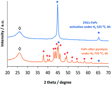 | ||
| Fig. 6 XRD patterns of the FePc based catalyst after pyrolysis and after activation under hydrogen. Fe (★); Fe3C (✦); carbon (◊). | ||
The peak positions in the XRD patterns recorded for the 2Cs%–FePc + CoPc catalyst were found to be identical (Fig. S5 in the ESI†) to those observed for 10Cs%–FePc. This confirms that Co is dissolved in the iron phase, forming an alloy, as suggested previously.31 This is in agreement with the observation of binary FeCo particles in the TEM images for the 2%Cs–FeCoPc sample (Fig. 5).
The iron and cobalt loadings were analyzed by inductively coupled plasma optical emission spectroscopy (ICP-OES, Table 2). The iron loading is around 19% wt and cobalt is 13% wt. In the sample prepared with Fe and Co (80/20 molar ratio), the final contents of Fe and Co are 13.3 and 3.6 wt%, respectively, as shown in Table 2.
Nitrogen adsorption–desorption isotherms and pore-size distributions of the catalysts were analyzed after the pyrolysis treatment and after the reaction with no significant changes observed. The values of the high surface areas and pore volumes are shown in Table 2, for the sample 2%Cs–FePc, 217 m2 g−1 (pore size 36 Å), and for the sample FePc + CoPc, 228 m2 g−1 (pore size 33 Å).
The dispersion of iron (FE, mean fraction of the total atoms exposed at the surface) and the number of active surface sites were calculated from the generalized equations39 detailed in the ESI† using the mean particle size of iron nanoparticles obtained with HR-TEM images considering 120 particles at least. In Table 3, the dispersion of iron and the number of active sites for the catalysts prepared from decomposition of metal phthalocyanines, with and without the addition of the alkali metal, are compared to the corresponding values for the commercial Fe-benchmark catalyst. It is clearly seen that a larger fraction of atoms are exposed at the surface, when the catalyst is based on nanoparticles like the Fe and Co catalysts derived from phthalocyanines, and consequently, a larger number of active surface sites are available for the reaction in the 2%Cs–FePc catalyst, compared to the commercial iron-based catalyst.
| Catalysts | Mean particle size (nm) | Metal dispersion FE (%) | Number of active surface sites (mol g−1) × 10−4 |
|---|---|---|---|
| Cs–FePc | 16.5 | 7.0 | 2.4 |
| Ba–CoPc | 18 | 6.8 | 1.6 |
| FePc | 80 | 1.5 | 0.5 |
| Fe-(KM1) | 100 | 1.2 | 1.5 |
In many cases, the catalyst preparation method (pyrolysis) and pretreatment (activation under hydrogen) strongly affect its catalytic performance. This was also observed for reported catalysts in the literature, including the commercial, iron-based ammonia synthesis catalyst for which the reduction must be carefully performed under particular conditions. To unravel different preparation and pretreatment methods, more investigation is currently underway in our laboratories in order to understand the effect of these parameters on catalysts developed from phthalocyanine precursors.
Conclusions
This paper describes the use of metal phthalocyanine precursors to develop novel catalysts for ammonia synthesis, which exhibit highly efficient and stable catalytic performance.The catalysts obtained by one-step pyrolysis of phthalocyanine precursors have metal nanoparticles confined in a nitrogen-doped carbon mesoporous matrix, which are efficient catalysts for ammonia synthesis. The iron/carbon and/or cobalt/carbon resulting materials, when promoted with alkali metals, are found to be highly active and stable catalysts, even outperforming the activity of a commercial iron-based catalyst, widely used for the ammonia synthesis process.
An alkali metal is found to be essential in order to improve the catalytic activity and stability. In order to elucidate the role of alkali metals, further investigation is required to distinguish the electronic or surface structural effects. This is currently under investigation in our laboratories.
Furthermore, the kinetic analysis corroborates that the RDS for ammonia synthesis over these catalytic systems derived from metal phthalocyanines could be any of the formation steps of NHx species rather than the N2 dissociation step, which only a few catalysts have achieved to date.
Although these results are very promising, more work is necessary to further boost the catalytic performance, especially at lower reaction temperatures. Based on the result shown here, the method of preparing catalysts from metal phthalocyanines can be used to develop more efficient ammonia synthesis catalysts for lower temperature processes.
Experimental
All materials were prepared by pyrolysis of iron phthalocyanines (FePc), which was purchased from Sigma-Aldrich, and were used without further purification, following a previously reported procedure. The detailed preparation procedure is the following: a certain amount of the precursor (iron phthalocyanine) was positioned in a porcelain boat placed in a tubular oven under nitrogen. The temperature was increased to 735 °C (heating rate: 2 °C min−1) and maintained at that temperature for 6 h. After the pyrolysis, the oven was cooled down to room temperature and the sample was passivated with 1%O2 in nitrogen for 6 h.The materials obtained after the pyrolysis of the phthalocyanine precursors was impregnated with aqueous solutions of cesium or barium nitrate (Cs = 2–10% wt for FePc and FePc + CoPc or Ba = 8% wt for CoPc).
For the control experiment, a sample of iron supported on carbon was prepared via the classical impregnation method, which was also promoted with cesium (2%Cs–10%Fe/carbon). To obtain the carbon support, commercially available activated carbon was heated under inert atmosphere (nitrogen) at 950 °C (heating rate: 5 °C min−1) for 12 h, followed by cooling to ambient temperature, washed with water to remove the dust fraction and dried at 100 °C overnight. The material thus prepared was impregnated with aqueous solutions of iron nitrate, dried and calcined in air at 220 °C (heating rate: 2 °C min−1). Then, 2% wt of Cs was impregnated using aqueous solutions of cesium nitrate.
Characterization of the materials
The chemical composition of the catalysts was determined from ICP and elemental analyses using inductively coupled plasma atomic emission spectroscopy (ICP-OES) on a Thermo-Electron 3580 instrument.
XRD measurements were performed on a Bruker D8 ADVANCE reflection diffractometer with the Bragg–Brentano geometry using CuKα1,2 radiation. For the identification of the phase composition, the program module “Pattern Fitting” implemented in STOE's WinXPOW software was used.
Specific surface areas and pore volumes were determined with a Micromeritics ASAP 2010 adsorption analyzer at liquid nitrogen temperature. Before measurements, the materials were degassed at a temperature of 150 °C for 10 h. The total pore volume was calculated by using the adsorbed volume at a relative pressure of 0.97. The BET surface area was estimated in the relative pressure range of 0.06–0.2.
Catalytic activity: the reaction of ammonia synthesis in a continuous flow reactor
Activity measurements of ammonia synthesis were carried out in a stainless-steel flow reactor supplied with a stoichiometric H2 + N2 mixture (Fig. S1 in the ESI†). The flow rate of hydrogen and nitrogen was controlled with Brooks mass flow-controllers. The pressure and temperature were kept constant using the corresponding controllers. In general, 200 mg of catalyst and a total flow of 40 ml min−1 are used for the experiments, keeping a H2![[thin space (1/6-em)]](https://www.rsc.org/images/entities/char_2009.gif) :
:![[thin space (1/6-em)]](https://www.rsc.org/images/entities/char_2009.gif) N2 ratio of 3
N2 ratio of 3![[thin space (1/6-em)]](https://www.rsc.org/images/entities/char_2009.gif) :
:![[thin space (1/6-em)]](https://www.rsc.org/images/entities/char_2009.gif) 1. The reactor outlet was connected to a Mass-Vac spectrometer for continuous monitoring of the NH3 mass signal (mass = 17). Ar (0.6 ml min−1) was used as a reference for the calibration of the instrument (Fig. S2 in the ESI†).
1. The reactor outlet was connected to a Mass-Vac spectrometer for continuous monitoring of the NH3 mass signal (mass = 17). Ar (0.6 ml min−1) was used as a reference for the calibration of the instrument (Fig. S2 in the ESI†).
Prior to measurements, the samples were reduced in a H2![[thin space (1/6-em)]](https://www.rsc.org/images/entities/char_2009.gif) :
:![[thin space (1/6-em)]](https://www.rsc.org/images/entities/char_2009.gif) N2 stream with a total flow of 40 ml min−1, at 485 °C for 36 h (cesium-promoted iron catalysts) and at 520 °C for 48 h (barium-promoted cobalt catalyst) (heating rate: 4 °C min−1), according to previously reported procedures. Activation at a higher temperature than those indicated resulted in a decrease of the catalytic performance of the iron-based catalysts. The signal of ammonia was monitored during the activation pre-treatment until this signal was constant, and after that, the catalysts were considered under steady-state conditions.
N2 stream with a total flow of 40 ml min−1, at 485 °C for 36 h (cesium-promoted iron catalysts) and at 520 °C for 48 h (barium-promoted cobalt catalyst) (heating rate: 4 °C min−1), according to previously reported procedures. Activation at a higher temperature than those indicated resulted in a decrease of the catalytic performance of the iron-based catalysts. The signal of ammonia was monitored during the activation pre-treatment until this signal was constant, and after that, the catalysts were considered under steady-state conditions.
The reaction temperature was varied in the range of 400–550 °C, and the pressure was from atmospheric to 7 MPa. During the experiments, each set of conditions was kept constant for 1 h to ensure that a stable performance was reached and to analyze the ammonia in the reactor outlet using the online connected Mass-Vac spectrometer. From the concentration of ammonia in the outlet gas, the reaction rate was determined and expressed in μmol NH3 g−1 h−1.
Funding sources
This research project has been funded by the SABIC Company.Conflicts of interest
There are no conflicts to declare.Acknowledgements
This research was supported by the SABIC Company. The authors acknowledge the resources and facilities provided by the King Abdullah University of Science and Technology. The authors also acknowledge the KAUST Analytical Core Lab (ACL) and especially the scientist Mohammed Khalid.References
- R. Schlogl, Angew. Chem., Int. Ed., 2003, 42, 2004–2008 CrossRef PubMed.
- M. Kitano, Y. Inoue, H. Ishikawa, K. Yamagata, T. Nakao, T. Tada, S. Matsuishi, T. Yokoyama, M. Hara and H. Hosono, Chem. Sci., 2016, 7, 4036–4043 RSC.
- J. C. J. K. Norskov, Chairs in U.S. DOE Roundtable: Sustainable ammonia synthesis report, Feb. 2106 Search PubMed.
- R. Schlögl, Ammonia Synthesis, in Handbook of Heterogeneous Catalysis, Wiley-VCH Verlag GmbH & Co. KGaA, 2008 Search PubMed.
- V. B. Shur and S. M. Yunusov, Russ. Chem. Bull., 1998, 47, 765–776 CrossRef CAS.
- T. H. Rod, A. Logadottir and J. K. Nørskov, J. Chem. Phys., 2000, 112, 5343–5347 CrossRef CAS.
- C. J. H. Jacobsen, S. Dahl, B. S. Clausen, S. Bahn, A. Logadottir and J. K. Nørskov, J. Am. Chem. Soc., 2001, 123, 8404–8405 CrossRef CAS PubMed.
- A. Vojvodic, A. J. Medford, F. Studt, F. Abild-Pedersen, T. S. Khan, T. Bligaard and J. K. Nørskov, Chem. Phys. Lett., 2014, 598, 108–112 CrossRef CAS.
- V. B. Volpin and V. P. Shut, New Trends in the Chemistry of Nitrogen Fixation, ed. J. Chatt, L. M. da Camara Pina and R. L. Richards, Acad. Press, London, 1980, p. 67 Search PubMed.
- T. A. Bazhenova and A. E. Shilov, Coord. Chem. Rev., 1995, 144, 69–145 CrossRef CAS.
- Y. Tanabe and Y. Nishibayashi, Coord. Chem. Rev., 2013, 257, 2551–2564 CrossRef CAS.
- L. Zhi, T. Gorelik, R. Friedlein, J. Wu, U. Kolb, W. R. Salaneck and K. Müllen, Small, 2005, 1, 798–801 CrossRef CAS PubMed.
- J. Masa, W. Xia, I. Sinev, A. Zhao, Z. Sun, S. Grützke, P. Weide, M. Muhler and W. Schuhmann, Angew. Chem., Int. Ed., 2014, 53, 8508–8512 CrossRef CAS PubMed.
- W.-D. Xue and R. Zhao, New J. Chem., 2014, 38, 2993–2998 RSC.
- Z. Zhang, Y. Qin, M. Dou, J. Ji and F. Wang, Nano Energy, 2016, 30, 426–433 CrossRef CAS.
- S.-Y. Ding and W. Wang, Chem. Soc. Rev., 2013, 42, 548–568 RSC.
- A. Aijaz, N. Fujiwara and Q. Xu, J. Am. Chem. Soc., 2014, 136, 6790–6793 CrossRef CAS PubMed.
- Z. Xiang, D. Cao, L. Huang, J. Shui, M. Wang and L. Dai, Adv. Mater., 2014, 26, 3315–3320 CrossRef CAS PubMed.
- A. B. Sorokin, Chem. Rev., 2013, 113, 8152–8191 CrossRef CAS PubMed.
- W. Arabczyk, U. Narkiewicz and D. Moszynski, Langmuir, 1999, 15, 5785–5789 CrossRef CAS.
- J. Sehested, C. J. H. Jacobsen, E. Törnqvist, S. Rokni and P. Stoltze, J. Catal., 1999, 188, 83–89 CrossRef CAS.
- R. Kojima and K.-I. Aika, Appl. Catal., A, 2001, 218, 121–128 CrossRef CAS.
- C. J. H. Jacobsen, Chem. Commun., 2000, 1057–1058 RSC.
- C. D. Zeinalipour-Yazdi, J. S. J. Hargreaves and C. R. A. Catlow, J. Phys. Chem. C, 2015, 119, 28368–28376 CrossRef CAS.
- S. R. Bare, D. R. Strongin and G. A. Somorjai, J. Phys. Chem., 1986, 90, 4726–4729 CrossRef CAS.
- D. R. Strongin and G. A. Somorjai, J. Catal., 1988, 109, 51–60 CrossRef CAS.
- D. R. Strongin and G. A. Somorjai, Catalytic Ammonia Synthesis Fundamentals and Practice, ed. J. R. Jennings, Plenum Press, New York, 1991 Search PubMed.
- S. Hagen, R. Barfod, R. Fehrmann, C. J. H. Jacobsen, H. T. Teunissen, K. Ståhl and I. Chorkendorff, Chem. Commun., 2002, 1206–1207 RSC.
- A. Jedynak, D. Szmigiel, W. Raróg, J. Zieliński, J. Pielaszek, P. Dłużewski and Z. Kowalczyk, Catal. Lett., 2002, 81, 213–218 CrossRef CAS.
- W. Raróg-Pilecka, A. Jedynak-Koczuk, J. Petryk, E. Miśkiewicz, S. Jodzis, Z. Kaszkur and Z. Kowalczyk, Appl. Catal., A, 2006, 300, 181–185 CrossRef.
- A. Tomita and Y. Tamai, J. Catal., 1972, 27, 293–300 CrossRef CAS.
- H. Tüysüz, F. Schüth, L. Zhi, K. Müllen and M. Comotti, ChemCatChem, 2015, 7, 1453–1459 CrossRef.
- Y. Gong, J. Wu, M. Kitano, J. Wang, T.-N. Ye, J. Li, Y. Kobayashi, K. Kishida, H. Abe, Y. Niwa, H. Yang, T. Tada and H. Hosono, Nat. Catal., 2018, 1, 178–185 CrossRef CAS.
- M. Kitano, S. Kanbara, Y. Inoue, N. Kuganathan, P. V. Sushko, T. Yokoyama, M. Hara and H. Hosono, Nat. Commun., 2015, 6, 6731 CrossRef CAS PubMed.
- P. Wang, F. Chang, W. Gao, J. Guo, G. Wu, T. He and P. Chen, Nat. Chem., 2016, 9, 64 CrossRef PubMed.
- M. Kitano, Y. Inoue, M. Sasase, K. Kishida, Y. Kobayashi, K. Nishiyama, T. Tada, S. Kawamura, T. Yokoyama, M. Hara and H. Hosono, Angew. Chem., Int. Ed., 2018, 57, 2648–2652 CrossRef CAS PubMed.
- K. Aika, M. Kumasaka, T. Oma, O. Kato, H. Matsuda, N. Watanabe, K. Yamazaki, A. Ozaki and T. Onishi, Appl. Catal., 1986, 28, 57–68 CrossRef CAS.
- C. D. Zeinalipour-Yazdi, J. S. J. Hargreaves and C. R. A. Catlow, J. Phys. Chem. C, 2018, 122, 6078–6082 CrossRef CAS.
- P. Gallezot and G. Bergeret, in Handbook of Heterogeneous Catalysis, 2008, pp. 738–765 Search PubMed.
Footnote |
| † Electronic supplementary information (ESI) available. See DOI: 10.1039/c9cy02326g |
| This journal is © The Royal Society of Chemistry 2020 |


