 Open Access Article
Creative Commons Attribution 3.0 Unported Licence
How to approach flow chemistry
Mara
Guidi
ab,
Peter H.
Seeberger
ab and
Kerry
Gilmore
 *a
*a
aDepartment of Biomolecular Systems, Max-Planck-Institute of Colloids and Interfaces, Am Mühlenberg 1, 14476 Potsdam, Germany. E-mail: kerry.m.gilmore@uconn.edu
bFreie Universität Berlin, Institute of Chemistry and Biochemistry, Arnimallee 22, 14195 Berlin, Germany
First published on 3rd November 2020
Abstract
Flow chemistry is a widely explored technology whose intrinsic features both facilitate and provide reproducible access to a broad range of chemical processes that are otherwise inefficient or problematic. At its core, a flow chemistry module is a stable set of conditions – traditionally thought of as an externally applied means of activation/control (e.g. heat or light) – through which reagents are passed. In an attempt to simplify the teaching and dissemination of this field, we envisioned that the key advantages of the technique, such as reproducibility and the correlation between reaction time and position within the reactor, allow for the redefinition of a flow module to a more synthetically relevant one based on the overall induced effect. We suggest a rethinking of the approach to flow modules, distributing them in two subclasses: transformers and generators, which can be described respectively as a set of conditions for either performing a specific transformation or for generating a reactive intermediate. The chemistry achieved by transformers and generators is (ideally) independent of the substrate introduced, meaning that they must be robust to small adjustments necessary for the adaptation to different starting materials and reagents while ensuring the same chemical outcome. These redefined modules can be used for single-step reactions or in multistep processes, where modules can be connected to each other in reconfigurable combinations to create chemical assembly systems (CAS) targeting compounds and libraries sharing structural cores. With this tutorial review, we provide a guide to the overall approach to flow chemistry, discussing the key parameters for the design of transformers and generators as well as the development of chemical assembly systems.
Key learning points• How the attributes of flow chemistry can be fully exploited to enable chemical synthesis.• Flow chemistry provides reproducible access to experimental conditions and should be thought in terms of capabilities, not components. • Flow modules are the conditions (including equipment) to chemoselectively either induce a functional group transformation/coupling or generate a reactive intermediate • Flow modules can be used in isolation or interchangeable to create assembly lines for chemical synthesis. • Processes can be developed to target core functionalities instead of specific molecules, significantly increasing the capabilities and output. |
The use of flow chemistry has seen a meteoric rise in the chemical community. The broad versatility in applications is thanks to the modular nature of the approach, allowing for the facile integration of new conditions, equipment, analytics, automation, and types of reagents for both single and multistep processes. The foundational, distinguishing feature of the approach is a high degree of precision in the delivery of reagents/solutions and excellent control over the conditions to which the solutions are exposed. Precise control results in excellent reproducibility and safety – making flow chemistry applicable not only to a range of disciplines, but also to researchers from university teaching labs to production-scale process chemists.
Organic synthesis has arguably benefited the most from the incorporation of flow chemical methodology, bringing reproducibility and expanded potential to a highly physical skill-based field of research. Flow chemistry is at least partially responsible for the recent rapid development and incorporation of photochemistry in synthesis, while access to reactive intermediates has allowed for transformations to be efficiently utilized that are essentially impossible to perform otherwise. Increasingly, both home-built and commercial flow chemical systems are being automated, opening the door to standardization of data generation, incorporation of optimization and machine learning algorithms, and most importantly the significant increase in access to the products and potential of organic synthesis to non-specialists.
In order to fully exploit the potential of flow chemistry, a chemist must primarily be able to discern when and how flow could be beneficial. This ability comes first and foremost with a firm grasp on the chemistry that is to be performed and the inherent issues – both process and mechanistic – thereof. The stumbling block often comes as chemists focus on the what of flow, which tools/equipment to use in order to perform a transformation or sequence continuously. Knowledge of the available flow chemistry equipment – at least the capabilities and strengths/weaknesses – is important. This information has been covered extensively in both broad and hyper-specific research and review articles over the last twenty years, creating an ever-expanding encyclopedia of flow chemistry hardware and examples of its capabilities.1
With the “facts” of flow chemistry – the what – readily available to researchers, it is prudent to discuss how flow chemistry should be used, and more importantly how flow chemistry is discussed and approached. The key attribute of the technique is the high degree of control over the physical process/conditions that provides excellent reproducibility. This affords the opportunity to expand the concept of modularity in flow chemistry from one focused on what equipment can be used to how processes can be used to expand our synthetic capabilities and potential.
Organic synthesis is traditionally taught as a collection of concepts, such as types of reactions (e.g. oxidation, reduction, substitution) and reactive intermediates (e.g. carbocation, carbanion, radicals), that can be exploited – either individually or in conjunction – to successfully synthesize a given target. The exact conditions/process for a specific transformation are secondary – the primary focus remains how one can use the available tools to better perform chemical synthesis.
In this tutorial review, we present flow chemistry in the same way, to show current and future users how flow chemistry can be thought of, approached, and utilized to maximize efforts in synthesis, methodology, and process development. We will discuss how flow chemistry should be approached in terms of its capacity to reproducibly perform processes where and when it is desired, providing standardizable access to types of transformations and reactive intermediates. This standardizable access to both transformations/intermediates is defined as a flow chemistry module, and is further broken down as described below. These modules can be used individually for single step processes, or together as interchangeable pieces of a multistep – or telescoped – process.
1. Definitions
1.1 Modules
At its core, a flow chemistry module is a stable set of conditions inducing an overall effect on a flowing stream of reagents: with this effect being a specific transformation or the generation of a reactive intermediate. Herein, we propose to classify these types of modules as “transformers” and “generators”, respectively. A transformer is a flow module where a specific set of chemical conditions and equipment are used to chemoselectively and reproducibly introduce a coupling or functional group modification. A generator is a flow module whose sole purpose is to generate a reactive intermediate (cation, radical, anion, excited state) at a specific space/time in a process, which can be utilized for study, trapped in situ, or consumed in a subsequent module.1.2 Telescoping
Transformers and generators are excellent means of reproducibly performing single step transformations. However, one of the strengths of flow chemistry is the relative ease in the ability to connect two or more modules to create a multi-step process; whether that is combining synthesis and work-up/purification, or stitching together multiple synthesis operations in the pursuit of a target molecule. In flow chemistry, when multiple units of operation are linked together in a continuous system it is called a telescoped process.The advantages of such a process are significant, with reductions in purification steps, time of synthesis, waste, and manual operations. That said, there are several considerations and limitations that must be considered as well. The flow rate is always increasing (due to the addition of feed lines), meaning that if one of the latter transformations requires a long residence time, a larger reactor is required to accommodate. Byproducts and unused reagents from previous steps are carried through to the subsequent modules. These can sometimes be removed via inline workups (creating more complex processes), but if not they can have a significant impact on the yield, selectivity, or even the composition of the molecular structure produced.2 The same goes for solvents. While prototypes and reagent-specific workarounds exist, the general rule of thumb is once something is added to a multistep flow process, it is there throughout – for better, or more commonly, for worse.
1.3 Chemical assembly systems
As implied above, the more units are linked together, the more complex the system becomes. This is true from a hardware perspective – having enough compatible equipment – an operations perspective – getting all equipment running correctly and simultaneously, reaching steady-state – and a chemical perspective – potential solvent/byproduct/solubility issues. Perhaps the most painful aspect, however, is that each telescoped process is typically designed to make one specific molecule, meaning that once complete, the entire process must be broken down and redesigned and rebuilt for the next target.Desirable small molecules – whether pharmaceuticals or otherwise – often share similar structural cores, and chemists typically synthesize libraries of derivatives where side chains of these cores are varied. By developing telescoped processes which aim to synthesize structural cores as opposed to specific molecules, entire libraries can be rapidly created simply by changing the starting materials/reagents being added to the process. Further, by seeing flow modules as transformers/generators as opposed to reagent-specific operations, it can be seen that these modules are interchangeable as determined by the desired order of operations. This approach of using transformers/generators interchangeably to target structural cores is a generalized method called chemical assembly systems3 that allow for the rapid synthesis not only of variants of certain motifs, but also different classes of compounds simply by rearranging the modules.
2. Know your flow
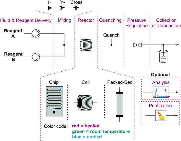
Performing reactions in flow requires a bit more thought and planning than the equivalent batch process. This is due to a number of considerations. The first question is whether there are actually chemical or process reasons for running the reaction in flow1 as opposed to more simply in a flask. Once justified, one must design both the experiment and the process (equipment, arrangement, and conditions). The simplest flow process is monophasic where no precipitation occurs – as this causes clogging of the tubing and thus failure of the process. Homogeneous conditions allow you to deliver premade solutions via syringe or HPLC pumps at the desired flow rates (determining stoichiometry) to a mixing unit. The mixed solution then flows into the reactor under pre-set conditions (heat, cold, light, electricity, etc.) and is exposed to those conditions for a length of time determined by the size of the reactor divided by the total flow rate of the solution. The entire system can be pressurized using a back pressure regulator, used to increase solubility of gases or perform reactions above the boiling points of reagents/solvents (Fig. 1). Exhaustive descriptions of every component of a wide range of potential flow processes can be found in recent publications and references therein.1,4While monophasic processes are simplest, there are numerous and significant advantages to performing multiphasic reactions in flow. Gases or immiscible solvents can be added to a flow solution via a simple T- or Y-mixer to easily generate a series of alternating slugs, the relative sizes of which are determined by the respective flow rates. Biphasic reactions and/or work-ups are generally accelerated using this technique when compared to batch processes due to the significant increase in surface areas between the layers and the increased mixing within each liquid slug. Gas/liquid reactions do not suffer from headspace issues and the solubility of the gas in the solution can be increased by pressurization.5
While the undesired formation of solids can present challenges in a flow system, solid reagents and catalysts can be used in flow effectively, in particular when preloaded into a column or cartridge to create a packed bed reactor. Fully heterogeneous catalytic reactions perform well in packed bed reactors, as the effective molarity of the catalyst at the point of reaction is significantly higher than in a batch catalytic process. The turn-over number of the catalyst is determined by the concentration of the solution, the residence time, and how long the process runs for. The only potential issues with this approach unique to flow would be leaching of the catalyst into solution, resulting in at best uneven distribution of catalyst within the packed bed and at worst loss of catalyst from the column.6 The leaching of catalyst and reagents from a packed bed can be used to deliver poorly soluble species, such as sodium fluoride (NaF) or sodium borohydride (NaBH4), however this is not a widely used technique.1
3. Approaching flow
Returning briefly to the thought process behind performing reactions in flow. There are a few types of chemistries that perform better under continuous conditions than in batch due to the inherent advantages of the flow reactor and process. Using well designed mixing units, two miscible solutions can be fully mixed down to the nanosecond timescale,7 making fast reactions an excellent choice for flow chemistry. As reaction time is directly related to the position in a reactor, the flow regime allows for precise control of intermediate generation and utilization (vide infra). The increased surface area of flow reactors affords excellent temperature control and light penetration, providing a general increase in control and efficiency of related transformations.One significant challenge to those new to the field – and often those experienced in it as well – is how to start a new investigation in flow. In batch this is more straight-forward, we would simply weigh the solid reagents, dissolve or suspend the reagent mixture into a solvent, add liquid reagents neat or as diluted solutions, and apply the required conditions (heat, cooling, light). Whether the reaction mixture is heterogeneous at the beginning or end doesn’t matter. One periodically takes samples, runs a TLC, and waits until the starting material is consumed. Unfortunately, you cannot do this in flow – which is why our group and others will, generally, quickly screen conditions in batch prior to developing a flow process to get a feel for the parameters and potential challenges.
In flow, we must decide on the process set-up supported by solubility tests, equipment geometry, etc. and then select an initial set of conditions, including: flow rates that determine stoichiometry and reaction time, concentrations, as well as reactor conditions and size. The solution exiting the reactor is collected, worked up if required, and analysed. Based on the results, a next set of conditions can then be tested. The procedures can be partially accelerated by using in-line analytics when the stream directly passes through an analytical device like an IR, NMR, or UV. However, in-line analytics are both expensive and can complicate reaction set-ups during the exploratory phase.
With an ever increasing number of literature examples to base initial tests on, initial screening and development is becoming easier. Therefore, we can begin to think more generally about how we approach a new flow process. Each transformation or synthesis in flow should not be developed in isolation or considered a “one-off”. While there are certainly specialized reactors/conditions, in general the set-ups and conditions that have been developed can be considered reproducible and (ideally) selective means of performing a chemical reaction. This includes functional group modifications, coupling reactions, or the generation, study, and utilization of reactive intermediates. Categorized as such, the flow chemistry literature can be reorganized from a series of specific examples to a collection of modules, equipment, and parameters to affect a desired chemical process, that can be utilized either in isolation or in combination to achieve our chemical goal. This toolbox for mechanistic and synthetic chemists can be utilized to minimize the challenges and hurdles in adopting the technique and hopefully providing a means of improved reproducibility and efficiency of research. In the following sections, we break down the flow literature into two types of modules – transformers, where flow conditions effect a specific chemical modification, and generators, where flow conditions effect the production of a reactive intermediate to be utilized in a multistep process. Finally, we will show how these modules can be used in interchangeable combinations to create multistep syntheses targeting cores for the rapid synthesis of collections of molecules.
4. Transformers
Organic chemistry is traditionally broken down into sets and series of functional group transformations and flow modules can be categorized similarly. The conditions to reproducibly induce a given transformation are comprised of the reagents required, the environmental parameters, and the equipment setup. If the chemistry is designed well, these conditions can result in a transferrable module capable of reproducible, selective functional group modification(s) independent of the starting material utilized. Just as in batch processes, different methods exist to induce a given transformation, and the module utilized should be based on chemical compatibility, availability of equipment, and byproducts generated. In this section we will discuss flow transformers that have been developed for the adaptable and substrate independent induction of types of organic reactions. These transformers have been organized by the class of chemical transformation, and representative examples of each are discussed.4.1 Oxidation modules
Numerous techniques and protocols have been developed to perform oxidation reactions in flow addressing practical and chemical challenges connected to working with toxic, flammable, and/or explosive oxidative reagents. While examples exist using heterogeneous oxidants, the majority of oxidation modules can be broken down into two classes of oxidation modules; the use of oxygen in gas/liquid modules and soluble oxidants in liquid/liquid systems, the latter also covering monophasic oxidations.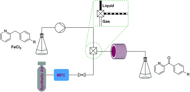 | ||
| Fig. 2 Transformer 1 – oxidation: using oxygen, creating a biphasic gas–liquid system using a T-mixer, exemplified by a benzylic oxidation procedure with iron(III) chloride.10 | ||
Aerobic oxidations in such setups often use soluble catalysts containing precious metals, palladium being the most studied. Reagents and catalysts are contained in a premade solution, which is mixed with oxygen gas or air and delivered to a reactor – generally at ambient or elevated temperature.8,9 Cheaper catalysts have also been studied and a good example of such a two phase process is a gas–liquid continuous flow reactor used for the aerobic oxidation of 2-benzylpyridines that employs FeCl3.10 Similar transformers employing more expensive and elaborate homogeneous catalysts are used to oxidize alkenes, alcohols, aldehydes and ketones.8
This process uses synthetic air and an inexpensive iron(III) chloride homogeneous catalyst (5 mol%). The reaction can be run fairly concentrated (starting material [1.2 M]) and at high temperature (200 °C). The setup consists of a liquid and a gas feed mixed by a T-mixer containing a pressure reducer and a repurposed GC oven containing a stainless steel coil as a reactor. However, reactions using oxygen gas/air can also be performed using simple T-mixers and in fluorinated polymer tubing such as PTFE or FEP. The specific temperature required for the oxidation will be reaction specific.
A showcase of this oxidation module is the anti-Markovnikov Wacker oxidation of styrenes to arylacetaldehydes.12 Oxygen was efficiently delivered to a solution containing styrene and a homogeneous palladium/copper catalytic system (each 5 mol%) under pressure (25 bar) maintained by a back pressure regulator. The oxygen-enriched monophasic solution exited the tube-in-tube reactor and passed into a reactor coil held at 60 °C. Using this setup, a number of styrenes were converted to the anti-Markovnicov aldehyde in good yields and exhibited good selectivity over the potential Markovnikov and the over-oxidation products (Fig. 3).
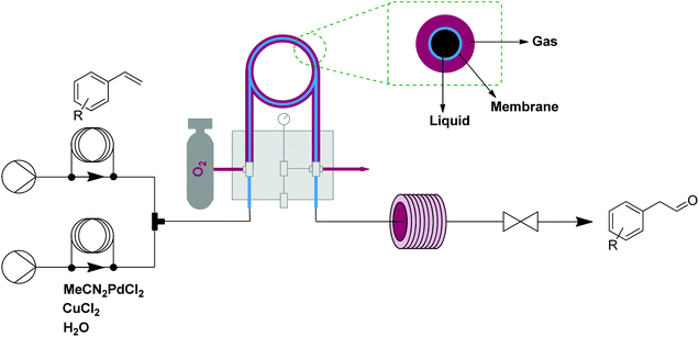 | ||
| Fig. 3 Transformer 2 – oxidation: using oxygen, delivered by a tube-in-tube reactor, showcased with the transformation of styrenes into aldehydes.12 | ||
However, even with simple and general applications such as this, issues can arise. While precipitation can occur anywhere in a flow system, the two main places are either inside a reactor due to product/byproduct crashing out, or at the mixer when two solutions first meet. In this work, there were issues with manganese dioxide falling out of solution at the exit of the T-mixer. The challenge was easily addressed by submerging the T-mixer in an ultrasonic bath that prevented any aggregation of manganese dioxide precipitate (Fig. 4).
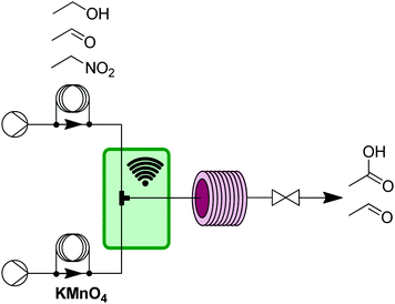 | ||
| Fig. 4 Transformer 3 – oxidation: using a liquid phase oxidant and an ultrasonic bath (green box) to avoid aggregation of precipitants resulting from oxidation byproducts.13 | ||
4.2 Reductions
Reductions can be performed using gaseous hydrogen or soluble reductants, by using adaptations of the oxidation setups described above. Safety and control over reductions is much better in flow than in Bach syntheses. Hydrogenations generally require high pressures and combine pyrophoric catalysts with a highly flammable gas.14 Liquid reductants, such as hydride sources, often face selectivity issues, as products may be susceptible to over-reduction. These issues can be reproducibly addressed using flow reduction transformers.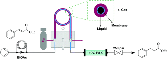 | ||
| Fig. 5 Transformer 4 – reduction: using hydrogen gas delivered by a tube in tube reactor and catalyst via a packed bed reactor (where the reduction takes place).15 | ||
 | ||
| Fig. 6 Transformer 5 – reduction: using in situ generated hydrogen by electrolysis of water, which under pressure creates a saturated solution that passes through a packed bed reactor containing the catalyst.16 | ||
Transformer 6 consists of two PFA reactors – for reduction and subsequent quenching – held at low temperature (Fig. 7). Solutions first pass through precooling loops to ensure controlled reactivity at sub-ambient temperatures and mixing is achieved using T-mixers. Mixing is critical for the efficiency of this reaction, and while this can be achieved using structured mixers, better mixing with T-mixers can be achieved using higher flow rates. The reduction of esters to aldehydes at cryogenic temperature (−78 °C) was fully selective and with an extremely short residence time (<50 ms), allowing for very high throughput for this transformer (>1.8 kg per day for ethyl hydrocinnamate) with only a 23 μl reactor (R1).17
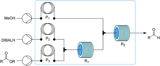 | ||
| Fig. 7 Transformer 6 – reduction: controlled homogeneous partial reduction of esters to aldehydes using hydride.17 Blue box corresponds to the chilled section of the transformer. | ||
4.3 Olefination reactions
Numerous flow protocols exist for highly adaptable homogeneous olefinations, including Wittig, Knoevenagel, and Horner–Wadsworth–Emmons couplings. These reactions are generally carried out in ambient or elevated temperature tubular reactors with reagents delivered by at least two liquid feeds. In flow, reaction times can sometimes be significantly shortened for these reactions due to the accessible high temperatures and pressures.1,18 | ||
| Fig. 8 Transformer 7 – olefination: a packed bed reactor capable of catalyzing and purifying Horner–Wadsworth–Emmons olefinations.19 | ||
4.4 Huisgen cycloadditions
Cycloadditions are powerful class of transformations, often characterized by their selectivity and minimal byproducts. The Huisgen 1,3-dipolar cycloaddition of an azide and alkyne is the classic example, and has become the epitome of “click” chemistry.20 The Cu(I)-catalyzed version of the azide–alkyne cycloaddition reaction (CuAAC) leads to 1,4-disubstituted 1,2,3-triazoles and its extreme versatility and robustness has resulted in a wide range of applications. The reaction benefits from continuous conditions due to its safety in handling potentially explosive azides even under harsh conditions, better mixing to potentially lower catalyst loading, and inline separation/purification. | ||
| Fig. 9 Transformer 8 – CuAAC: a copper coil serves as both reactor and catalyst source.21 | ||
 | ||
| Fig. 11 Transformer 10 – CuAAC: a packed-bed system for CuAAC with modular scavenging units for both metal and excess azide.24 | ||
5. Generators
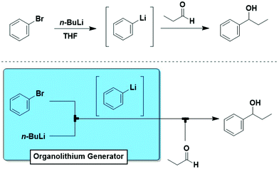
The “generator” concept is commonly used to indicate a module for the continuous in situ production of hazardous materials.25 Here, we expand this concept to include all reactive intermediates that can be generated in situ and on-demand.One of the most important, but often underestimated features of flow chemistry is the direct correlation between reaction time and physical position in flow reactors. In a given reactor, the reaction time is a function of flow rate and volume (a factor of both tube diameter and length). The implications are significant, particularly for fast reactions or those proceeding through reactive intermediates. When one writes out a reaction, reagents are drawn coming together, creating an intermediate such as an organolithium species that then reacts e.g. with an electrophile to give the desired product. Traditionally, all these species are present together presenting multiple potential reaction pathways, and cryogenic conditions are required to attempt to control reactivity. However, flow modules can be designed to create a system identical to how it is drawn (Fig. 12). Thereby, intermediates and processes are reproducibly accessable that cannot be effectively or safely carried out in batch.
This concept is best exemplified by the “flash chemistry” of Yoshida, whose work perfectly exploited the space-time correlation of flow chemistry. Flash chemistry relies on very fast reactions (a second or less) involving highly reactive and unstable species that cannot be harnessed by traditional methods.26
Generators are modules that utilize liquids or gases to create a reactive species and are modules incorporated into larger flow processes. As with transformers, we will organize our discussion of generators based on capability (i.e. type of intermediate formed) and will highlight for each the most relevant example(s) in the literature.
5.1 Carbocations
Carbocations are positively charged intermediates that play key roles in various organic reactions, but are, due to their unstable and transient nature, difficult to isolate and accumulate. Generating carbocations continuously via continuous flow techniques provides stable access to these valuable species, which can then be trapped by nucleophiles prior to undergoing side reactions. | ||
| Fig. 13 Generator 1 – cations: electrolytic generation of iminium ions, capable of inline monitoring, delivered to a stream containing the nucleophile.27 | ||
5.2 Benzyne
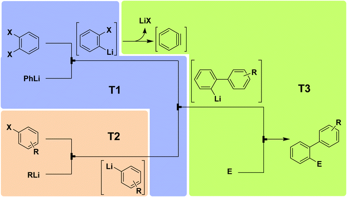 | ||
| Fig. 14 Generator 2 – benzyne: fully adjustable three-component system for generating and utilizing benzyne with different nucleophiles and electrophiles.28 The three temperature zones are shown with colored boxes. | ||
5.3 Carbanions
One of the most commonly employed carbanionic synthons are organometallic species such as organolithium and organomagnesium compounds that contain a very polar carbon–metal bond with electron density heavily concentrated on the carbon atom. These highly reactive species are potentially hazardous due to the exothermicity of their reactions, thus rendering control over chemoselectivity and overreactions difficult. Organometallic species are popular among flow chemists as they can be safely generated and manipulated in situ.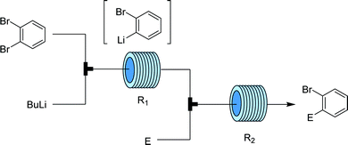 | ||
| Fig. 15 Generator 3 – aryllithium: precise design allows for trapping of o-haloaryl lithium species prior to side reactions.29 | ||
5.4 Radicals
Besides carbocations and carbanions, radicals are the third major class of electronically unsatisfied reactive species. Radicals are molecules with an unpaired valence electron and are very reactive and as such, transient. As widely reported, microfluidic devices can overcome mass and energy transport limitations even for fast and exothermic reactions, making the generation and utilization of radicals better controlled in microflow systems.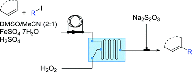 | ||
| Fig. 16 Generator 4 – alkyl radicals: two-step process for formation of alkyl radicals, with selective trapping with an in situ alkene.30 | ||
Operationally, the generator is a straight-forward two-feed flow setup driven by syringe pumps. In the first feed there is a solution containing the aromatic substrate, the alkyl iodide, FeSO4·7H2O (as Fe(II) catalyst) and H2SO4 (added to enhance the solubility of the Fe(II) salt and to prevent its oxidation) in DMSO while the second feed contains hydrogen peroxide. The residence time unit can be either a micromixer of various designs or a combination of Y-connections and PFA tubing.
5.5 Diazo compounds
Diazo compounds are highly reactive organic molecules well known for both their synthetic potential as well as for the safety hazards associated with them. These reasons – as well as the facility of pressurization to control the liberated gas – are excellent arguments for the development of a flow generator for these inherently unstable compounds. A thorough review article on the use of continuous flow for safe generation and use of diazo compounds details numerous good examples of flow generators for such species.31 Here, we highlight four of them, which exploit different chemistries and flow setups, approaching the challenge in distinct but valuable ways. These can be further broken down into gaseous (diazomethane) and liquid diazo generators.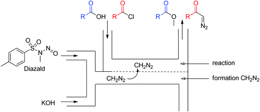 | ||
| Fig. 17 Generator 5 – diazomethane: dual stream in situ generation and reaction of diazomethane via a membrane reactor.32 | ||
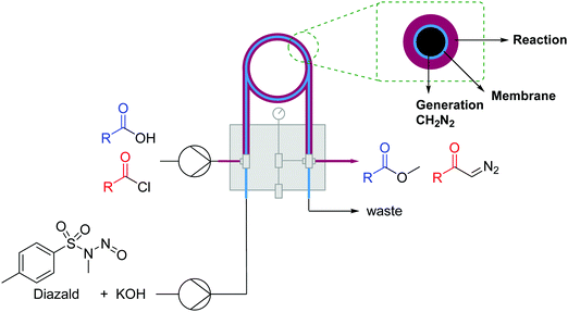 | ||
| Fig. 18 Generator 6 – dizaomethane: generation of diazomethane and reactions thereof in a tube-in-tube reactor.33 | ||
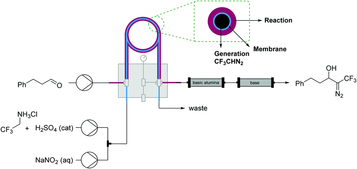 | ||
| Fig. 19 Generator 7 – alkyl diazo compounds: generation of fluorinated diazo compounds and use via a tube-in-tube reactor. The generator is coupled with a packed-bed reactor to catalyze an aldol coupling of the formed diazo intermediate.34 | ||
 | ||
| Fig. 20 Generator 8 – benzyl diazo compounds: MnO2 packed bed module generates diazo compounds via oxidation of hydrazones. | ||
While the column is consumed/deactivated during the course of the reaction, a protocol for the regeneration and re-use of the MnO2 column was also established. The spent manganese oxide could be oxidized by passing a solution of tert-butyl hydroperoxide through the column. Interestingly, the regenerated column produced diazo compound without the need for a pre-conditioning phase. MnO2 was recycled over three cycles with just a slight decrease in reactivity after each time.
5.6 Phosgene
Phosgene is a very useful gaseous reagent in organic synthesis. However, it is toxic and hazardous – making handling and accumulation of such species dangerous. As discussed for diazomethane, flow generators can enable continuous in situ generation and consumption of hazardous gases within a closed system, opening the doors to their application in many types of chemistries otherwise carefully avoided.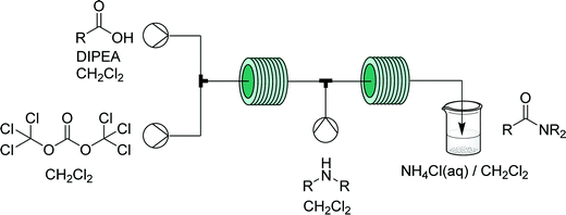 | ||
| Fig. 21 Generator 9 – phosgene: safe in situ generation and use of phosgene, exemplified by its use in the synthesis of acid chlorides – immediately used in a telescoped synthesis of amides.36 | ||
5.7 Singlet oxygen
Singlet oxygen (1O2) is a low cost and green reagent attractive for its versatility in a plethora of reactions, including heteroatom oxidations, ene-reactions, and cycloaddition reactions. 1O2 is usually generated through the excitation of triplet oxygen (3O2) by using a photoinitiator and light. It is a highly reactive, unstable, and explosive species and these features, together with the already mentioned benefits of microreactors in gas–liquid and photochemical processes, make 1O2 an excellent candidate for flow.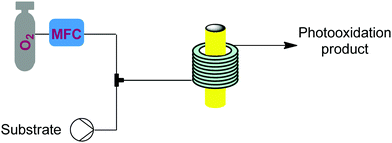 | ||
| Fig. 22 Generator 10 – singlet oxygen: continuous generation and use of singlet oxygen driven by energy transfer from an excited dye, driven by either a UV or LED lamp.37–41 | ||
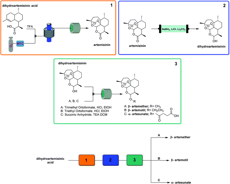
This generator can also be driven by visible light LEDs, and a truly wide breadth of chemistry has been achieved using singlet oxygen in flow with these simple generators and a simple room temperature residence time unit.8 Two examples showcase the flexibility of this generator. Dihydroartemisinic acid reacts with singlet oxygen, generated either using a pure dye39 or crude chlorophyll from Artemisia annua extraction,40 in an ene reaction to give an intermediate peroxide. When the reaction is performed in the presence of triflic acid, this unstable intermediate undergoes a cascade of reactions resulting in the active pharmaceutical ingredient (API) artemisinin. Without any changes to the generator and simply replacing the starting material solution, primary and secondary amines can be rapidly oxidized to the corresponding imine, which can be quantitatively trapped by an in situ cyanide source (unreactive in the generator) to give α-aminonitriles.41
6. Chemical assembly systems
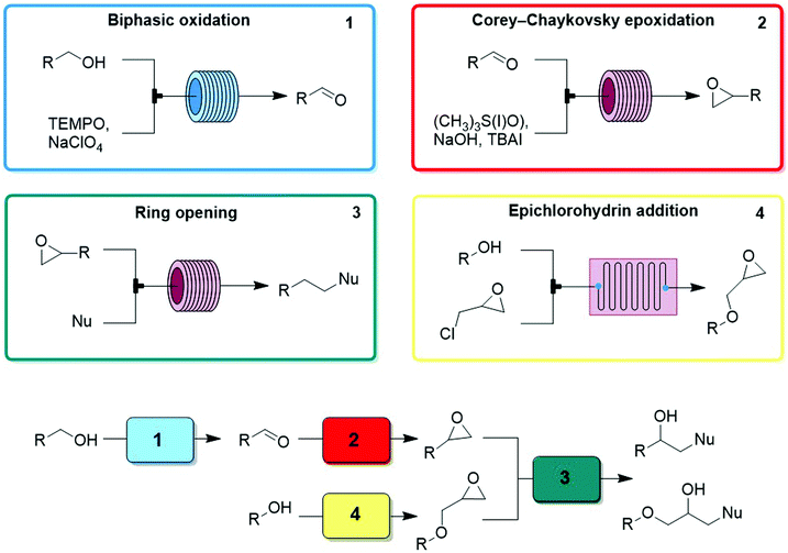
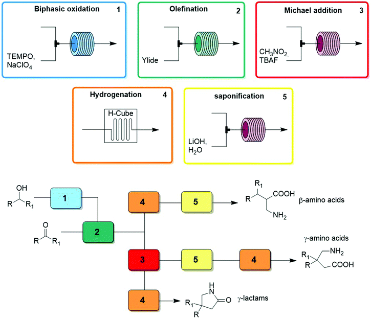
Thus far we have covered the best approaches to exploit flow reactors as reproducible sets of conditions with space and time directly linked by flow rate to induce a transformation. The synthetic potential further increases – as does the technical difficulty – when multiple transformers, generators, and combinations thereof are linked in series. These individual modules are designed to be chemoselective, and can be used interchangeably to create reconfigurable multistep processes. The processes, called chemical assembly systems (CAS)3 due to the their similarity to traditional assembly lines, combine modules focused solely on functional group transformations, can be used to target cores motives as opposed to specific target molecules. As such, compound collections can be generated by simply changing the starting materials entering the CAS sequence. A second layer of control over product outcome is derived from the reagents chosen, allowing for further functional groups or branching points to be included by e.g. transforming an aldehyde into an α,β-unsaturated ester via either a Horner–Wadsworth–Emmons or Knovenagel olefination. Finally, the order and choice of modules provides access to very different classes of target core structures (Fig. 23).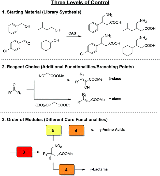 | ||
| Fig. 23 The concept of a chemical assembly system, exhibiting three levels of control over product outcome.3 | ||
Even when targeting different structural classes of compounds, reactions within their syntheses are often repeated, on different substrates or at a different point of the process. Therefore, the same modules can be exploited within the syntheses of different compounds simply by rearranging the combination of modules and passing different substrates through them. CAS are synthetic platforms presenting a pool of modules and reagents that can be arranged in different combinations in order to cover significant chemical space. In this section, we will highlight several multistep processes where several generators, transformers, or combinations thereof are linked together to create multistep processes targeting different structural cores.
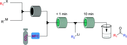
The α-aminonitriles produced upon amine oxidation/trapping in Fig. 22 are valuable intermediates towards a variety of core functionalities. This example illustrates how different target structures can be achieved from the same starting material by using a different series of modules. By coupling the α-aminonitrile generator to a high temperature/pressure reactor introducing an HCl solution, racemic α-amino acids can be produced, with side chains determined by the starting amine.44 Exchange of HCl for CO2 gas provides access to a class of heterocycles called hydantoins – though removal of the oxygen gas from the singlet oxygen generator is first required for this two-step CAS.45 Finally, replacement of the cyanide with a different carbon nucleophile, malononitrile, provides access to α-cyanoepoxides through a two-stage oxidation, where singlet oxygen generates both the imine and an equivalent of hydrogen peroxide, that in the second module oxidizes the intermediate electron-poor α,β-unsaturated ester into the corresponding epoxide (Fig. 25).2
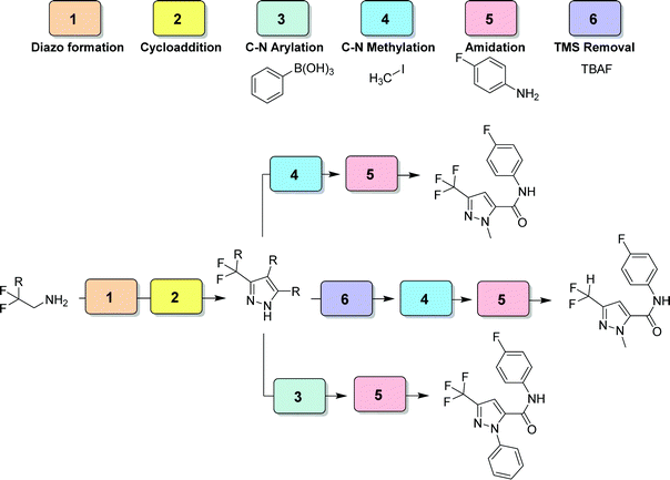 | ||
| Fig. 29 CAS 6 – pyrazole library: a six module divergent CAS exhibits controlled functionalization of multiple positions of the formed pyrazole moiety.48 | ||
7. Automated CAS
The chemical assembly systems presented above need manual intervention for modifications, whether the recombination of their modules between synthetic pathways or exchanging starting materials/reagents. Recent efforts have seen the evolution of flow chemistry towards automation, to accelerate and facilitate synthesis. Automation will also significantly help with the standardization of chemical processes – where being in flow is already an advantage.We will highlight two systems that use automation to control available reaction modules for single steps, linking them together in different combinations to achieve different multistep processes. The automated platforms are distinct based on their approach to how the respective modules are arranged, defined, and utilized in the system.
The reagents are connected to the process stack through a robotically manipulated switchboard, that connects the fluid pumps, outlets, and waste streams to each process module as required by the chosen chemical process. Two pumps are equipped with selector valves, which enable selection from up to 24 feedstocks each, thus allowing a wide variety of syntheses to be performed. The reaction modules include different laminar flow reactors of different volumes (100 ml to 3 ml), packed bed reactors (1 to 2 ml) capable of operating at temperatures from ambient to 200 °C and pressures up to 250 psig, and a membrane separator unit for liquid–liquid extraction. Fluid connections between adjacent units are achieved by vertically stacking them in the required order and a continuous stream of reagents is then passed through the sequence. The concept was demonstrated synthesizing six different active pharmaceutical ingredients (aspirin, secnidazole, lidocaine, diazepam, (S)-warfarin, and safinamide) and two libraries of quinapril and celecoxib derivatives (Fig. 30).
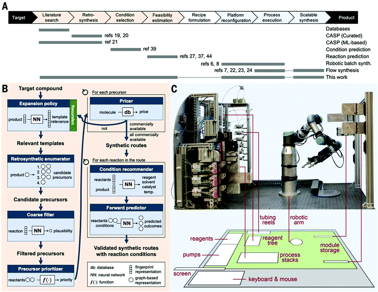 | ||
| Fig. 30 Auto-CAS 1 – linear syntheses: an automated, robotic platform for the flow synthesis of organic compounds informed by AI planning.49 From Science, 2019, 365, eaax1566. Reprinted with permission from AAAS. | ||
Such robotic systems have also been combined with software for artificial intelligence-driven synthesis planning. This allows for the automated proposal of synthetic routes through generalization of millions of published chemical reactions, validation in silico, then performing the synthesis on the automated platform.
The system is composed of ten valves (three injection valves and seven multi-position valves) that create different flow pathways through the instrument and the equally accessible reaction modules arranged radially in the central switching station (CSS). A reagent pool stores up to 14 solvents, liquid reagents, homogenous solutions, or synthesized intermediates in pressurized vessels. Reagents and solvents are delivered by two syringe pumps and allow for inline dilution. After each step, the reaction solution can be collected, cycled back through the system for the next step, or delivered to reagent storage. This final path allows for both convergent syntheses and multistep optimizations without manual intervention (Fig. 31).
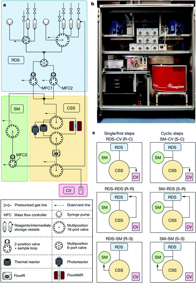 | ||
| Fig. 31 Auto-CAS 2 – radial syntheses: automated synthesis using a radial arrangement of equipment for the synthesis of organic molecules.50 From Nature, 2020, 579, 379–384. | ||
The system was showcased synthesizing the API rufinamide via two different synthetic routes and a library of 13 derivatives, using one generator (formation of differently substituted benzyl azides) and two transformers (one for amidation of methyl esters and one for click cycloaddition), all of which performed in the same physical reactor. Furthermore, the capabilities of the system were expanded with the integration of a photoreactor, providing access to transformations such as metallaphotoredox aryl aminations.
8. Conclusion
Flow chemistry has a number of inherent advantages compared to batch processes that increase reproducibility and safety, increase access to intermediates and conditions that are traditionally difficult to use, and allow for multistep processes to be performed more efficiently by linking multiple units. The flow chemistry field has significantly advanced in the last twenty years and many of the initial technical challenges and details of how these systems can and should be operated are now well established. With this strong foundation, less-technically inclined chemists can benefit from the technique and focus more on application and capability expansion. We created this tutorial on how flow chemistry can be thought of and used by broadening the focus from equipment to capabilities. From this point of view, the exact molecule and physical arrangement for that target is less important. What is more synthetically beneficial is the compartmentalization of flow chemistry capabilities – using control and reproducibility to generate reactive intermediates or perform selective transformations where and when they are needed in a synthetic process. While this still allows for target oriented synthesis, it also broadens our definition of target from a single molecule to a core functionality. In doing so, our processes become more modular and their components more transferrable, ideally allowing for new processes to be developed more readily than we could previously. With the automation of these systems, we approach the point of true standardization within the field, where desired transformations and syntheses can be reproducibly transferred between labs and literature while human error and physical skill can be increasingly removed from the chemical equation.Conflicts of interest
There are no conflicts to declare.Acknowledgements
We gratefully acknowledge the Max Planck Society and the Deutsche Forschungsgemeinschaft (FOR 2177) for their financial support. Open Access funding provided by the Max Planck Society.References
- M. B. Plutschack, B. Pieber, K. Gilmore and P. H. Seeberger, The Hitchhiker's Guide to Flow Chemistry, Chem. Rev., 2017, 117, 11796–11893 CrossRef CAS
.
- D. B. Ushakov, K. Gilmore and P. H. Seeberger, Consecutive oxygen-based oxidations convert amines to α-cyanoepoxides, Chem. Commun., 2014, 50, 12649–12651 RSC
.
- D. Ghislieri, K. Gilmore and P. H. Seeberger, Chemical Assembly Systems: Layered Control for Divergent, Continuous, Multistep Syntheses of Active Pharmaceutical Ingredients, Angew. Chem., Int. Ed., 2015, 54, 678–682 CAS
.
- J. Britton and T. F. Jamison, The assembly and use of continuous flow systems for chemical synthesis, Nat. Protoc., 2017, 12, 2423–2446 CrossRef CAS
.
- Y. Liu, G. Chen and J. Yue, Manipulation of gas-liquid-liquid systems in continuous flow microreactors for efficient reaction processes, J. Flow Chem., 2020, 10, 103–121 CrossRef CAS
.
- R. Greco, W. Goessler, D. Cantillo and C. O. Kappe, Benchmarking immobilized di- and triarylphosphine palladium catalysts for continuous-flow cross-coupling reactions: efficiency, durability, and metal leaching studies, ACS Catal., 2015, 5, 1303–1312 CrossRef CAS
.
- H. Kim, K. Min, K. Inoue, D. Jin Im, D. Kim and J. Yoshida, Submillisecond organic synthesis: Outpacing Fries rearrangement through microfluidic rapid mixing, Science, 2016, 352(6286), 691–694 CrossRef CAS
.
- C. A. Hone and C. O. Kappe, The Use of Molecular Oxygen for Liquid Phase Aerobic Oxidations in Continuous Flow, Top. Curr. Chem., 2019, 377, 2 CrossRef
.
- J. F. Greene, J. M. Hoover, D. S. Mannel, T. W. Root and S. S. Stahl, Continuous-Flow Aerobic Oxidation of Primary Alcohols with a Copper(I)/TEMPO Catalyst, Org. Process Res. Dev., 2013, 17, 1247–1251 CrossRef CAS
.
- B. Pieber and C. O. Kappe, Direct aerobic oxidation of 2-benzylpyridines in a gas–liquid continuous-flow regime using propylene carbonate as a solvent, Green Chem., 2013, 15, 320–324 RSC
.
- M. Brzozowski, M. O’Brien, S. V. Ley and A. Polyzos, Flow chemistry: intelligent processing of gas–liquid transformations using a tube-in-tube reactor, Acc. Chem. Res., 2015, 48(2), 349–362 CrossRef CAS
.
- S. L. Bourne and S. V. Ley, A Continuous Flow Solution to Achieving Efficient Aerobic Anti-Markovnikov Wacker Oxidation, Adv. Synth. Catal., 2013, 355, 1905–1910 CrossRef CAS
.
- J. Sedelmeier, S. V. Ley, I. R. Baxendale and M. Baumann, KMnO4-Mediated Oxidation as a Continuous Flow Process, Org. Lett., 2010, 12, 3618–3621 CrossRef CAS
.
- P. J. Cossar, L. Hizartzidis, M. I. Simone, A. McCluskey and C. P. Gordon, The expanding utility of continuous flow hydrogenation, Org. Biomol. Chem., 2015, 13, 7119–7130 RSC
.
- M. O’Brien, N. Taylor, A. Polyzos, I. R. Baxendale and S. V. Ley, Hydrogenation in flow: homogeneous and heterogeneous catalysis using Teflon AF-2400 to effect gas–liquid contact at elevated pressure, Chem. Sci., 2011, 2, 1250–1257 RSC
.
- R. V. Jones, L. Godorhazy, N. Varga, D. Szalay, L. Urge and F. Darvas, Continuous-Flow High Pressure Hydrogenation Reactor for Optimization and High-Throughput Synthesis, J. Comb. Chem., 2006, 8, 110–116 CrossRef CAS
.
- D. Webb and T. F. Jamison, Diisobutylaluminum Hydride Reductions Revitalized: A Fast, Robust, and Selective Continuous Flow System for Aldehyde Synthesis, Org. Lett., 2012, 14(2), 568–571 CrossRef CAS
.
- M. Viviano, T. N. Glasnov, B. Reichart, G. Tekautz and C. Oliver Kappe, A Scalable Two-Step Continuous Flow Synthesis of Nabumetone and Related 4-Aryl-2-butanones, Org. Process Res. Dev., 2011, 15, 858–870 CrossRef CAS
.
- W. Solodenko, U. Kunz, G. Jas and A. Kirschning, Polymer-Assisted Horner–Emmons Olefination Using PASSflow Reactors: Pure Products without Purification, Bioorg.
Med. Chem. Lett., 2002, 12, 1833–1835 CrossRef CAS
.
- H. C. Kolb, M. G. Finn and K. B. Sharpless, Click Chemistry: Diverse Chemical Function from a Few Good Reactions, Angew. Chem., Int. Ed., 2001, 40, 2004–2021 CrossRef CAS
.
- A. R. Bogdan and N. W. Sach, The Use of Copper Flow Reactor Technology for the Continuous Synthesis of 1,4-Disubstituted 1,2,3-Triazoles, Adv. Synth. Catal., 2009, 351, 849–854 CrossRef CAS
.
- A. C. Varas, T. Noel, Q. Wang and V. Hessel, Copper(I)-Catalyzed Azide–Alkyne Cycloadditions in Microflow: Catalyst Activity, High-T Operation, and an Integrated Continuous Copper Scavenging Unit, ChemSusChem, 2012, 5, 1703–1707 CrossRef CAS
.
- A. Adamo, P. L. Heider, N. Weeranoppanant and K. F. Jensen, Membrane-Based, Liquid–Liquid Separator with Integrated Pressure Control, Ind. Eng. Chem. Res., 2013, 52(31), 10802–10808 CrossRef CAS
.
- C. D. Smith, I. R. Baxendale, S. Lanners, J. J. Hayward, S. C. Smith and S. V. Ley, [3 + 2] Cycloaddition of acetylenes with azides to give 1,4-disubstituted 1,2,3-triazoles in a modular flow reactor, Org. Biomol. Chem., 2007, 5, 1559–1561 RSC
.
- D. Dallinger, B. Gutmann and C. O. Kappe, The Concept of Chemical Generators: On-Site On-Demand Production of Hazardous Reagents in Continuous Flow, Acc. Chem. Res., 2020, 53(7), 1330–1341 CrossRef CAS
.
- J. Yoshida, Y. Takahashia and A. Nagakia, Flash chemistry: flow chemistry that cannot be done in batch, Chem. Commun., 2013, 49, 9896–9904 RSC
.
- S. Suga, M. Okajima, K. Fujiwara and J. Yoshida, “Cation Flow” Method: A New Approach to Conventional and Combinatorial Organic Syntheses Using Electrochemical Microflow Systems, J. Am. Chem. Soc., 2001, 123, 7941–7942 CrossRef CAS
.
- A. Nagaki, D. Ichinari and J. Yoshida, Three-Component Coupling Based on Flash Chemistry. Carbolithiation of Benzyne with Functionalized Aryllithiums Followed by Reactions with Electrophiles, J. Am. Chem. Soc., 2014, 136, 12245–12248 CrossRef CAS
.
- H. Usutani, Y. Tomida, A. Nagaki, H. Okamoto, T. Nokami and J. Yoshida, Generation and Reactions of o-Bromophenyllithium without Benzyne Formation Using a Microreactor, J. Am. Chem. Soc., 2007, 129, 3046–3047 CrossRef CAS
.
- J. L. Monteiro, P. F. Carneiro, P. Elsner, D. M. Roberge, P. G. M. Wuts, K. C. Kurjan, B. Gutmann and C. O. Kappe, Continuous Flow Homolytic Aromatic Substitution with Electrophilic Radicals: A Fast and Scalable Protocol for Trifluoromethylation, Chem. – Eur. J., 2017, 23, 176–186 CrossRef CAS
.
- K. J. Hock and R. M. Koenigs, The Generation of Diazo Compounds in Continuous-Flow, Chem. – Eur. J., 2018, 24, 10571–10583 CrossRef CAS
.
- R. A. Maurya, C. P. Park, J. H. Lee and D. Kim, Continuous In Situ Generation, Separation, and Reaction of Diazomethane in a Dual-Channel Microreactor, Angew. Chem., Int. Ed., 2011, 50, 5952–5955 CrossRef CAS
.
- F. Mastronardi, B. Gutmann and C. O. Kappe, Continuous Flow Generation and Reactions of Anhydrous Diazomethane Using a Teflon AF-2400 Tube-in-Tube Reactor, Org. Lett., 2013, 15(21), 5591–5593 CrossRef
.
- B. Pieber and C. O. Kappe, Generation and Synthetic Application of Trifluoromethyl Diazomethane Utilizing Continuous Flow Technologies, Org. Lett., 2016, 18, 1076–1079 CrossRef CAS
.
- D. N. Tran, C. Battilocchio, S. Lou, J. M. Hawkins and S. V. Ley, Flow chemistry as a discovery tool to access sp2 – sp3 cross-coupling reactions via diazo compounds, Chem. Sci., 2015, 6, 1120–1125 RSC
.
- S. Fuse, N. Tanabe and T. Takahashi, Continuous in situ generation and reaction of phosgene in a microflow system, Chem. Commun., 2011, 47, 12661–12663 RSC
.
- F. Lévesque and P. H. Seeberger, Highly Efficient Continuous Flow Reactions Using Singlet Oxygen as a “Green” Reagent, Org. Lett., 2011, 13(19), 5008–5011 CrossRef
.
- B. D.
A. Hook, W. Dohle, P. R. Hirst, M. Pickworth, M. B. Berry and K. I. Booker-Milburn, A Practical Flow Reactor for Continuous Organic Photochemistry, J. Org. Chem., 2005, 70, 7558–7564 CrossRef CAS
.
- F. Lévesque and P. H. Seeberger, Continuous-Flow Synthesis of the Anti-Malaria Drug Artemisinin, Angew. Chem., Int. Ed., 2012, 51, 1706–1709 CrossRef
.
- S. Triemer, K. Gilmore, G. T. Vu, P. H. Seeberger and A. Seidel-Morgenstern, Literally Green Chemical Synthesis of Artemisinin from Plant Extracts, Angew. Chem., Int. Ed., 2018, 57, 5525–5528 CrossRef CAS
.
- D. B. Ushakov, K. Gilmore, D. Kopetzki, D. T. McQuade and P. H. Seeberger, Continuous-Flow Oxidative Cyanation of Primary and Secondary Amines Using Singlet Oxygen, Angew. Chem., Int. Ed., 2014, 53, 557–561 CrossRef CAS
.
- K. Gilmore, D. Kopetzki, J. W. Lee, Z. Horvath, D. T. McQuade, A. Seidel-Morgenstern and P. H. Seeberger, Continuous synthesis of artemisinin-derivedmedicines, Chem. Commun., 2014, 50, 12652–12655 RSC
.
- K. Gilmore, S. Vukelić, D. T. McQuade, B. Koksch and P. H. Seeberger, Continuous Reductions and Reductive Aminations Using Solid NaBH4, Org. Process Res. Dev., 2014, 18(12), 1771–1776 CrossRef CAS
.
- S. Vukelić, D. B. Ushakov, K. Gilmore, B. Koksch and P. H. Seeberger, Flow Synthesis of Fluorinated α-Amino Acids, Eur. J. Org. Chem., 2015, 3036–3039 CrossRef
.
- S. Vukelić, B. Koksch, P. H. Seeberger and K. Gilmore, A Sustainable, Semi-Continuous Flow Synthesis of Hydantoins, Chem. – Eur. J., 2016, 22, 13451–13454 CrossRef
.
- J. Wu, X. Yang, Z. He, X. Mao, T. A. Hatton and T. F. Jamison, Continuous Flow Synthesis of Ketones from Carbon Dioxide and Organolithium or Grignard Reagents, Angew. Chem., Int. Ed., 2014, 53, 8416–8420 CrossRef CAS
.
- T. Nobuta, G. Xiao, D. Ghislieri, K. Gilmore and P. H. Seeberger, Continuous and convergent access to vicinyl amino alcohols, Chem. Commun., 2015, 51, 15133–15136 RSC
.
- J. Britton and T. F. Jamison, A Unified Continuous Flow Assembly-Line Synthesis of Highly Substituted Pyrazoles and Pyrazolines, Angew. Chem., Int. Ed., 2017, 56, 8823–8827 CrossRef CAS
.
- C. W. Coley, D. A. Thomas III, J. A. M. Lummiss, J. N. Jaworski, C. P. Breen, V. Schultz, T. Hart, J. S. Fishman, L. Rogers, H. Gao, R. W. Hicklin, P. P. Plehiers, J. Byington, J. S. Piotti, W. H. Green, A. J. Hart, T. F. Jamison and K. F. Jensen, A robotic platform for flow synthesis of organic compounds informed by AI planning, Science, 2019, 365, eaax1566 CrossRef CAS
.
- S. Chatterjee, M. Guidi, P. H. Seeberger and K. Gilmore, Automated radial synthesis of organic molecules, Nature, 2020, 579, 379–384 CrossRef CAS
.
| This journal is © The Royal Society of Chemistry 2020 |


