
 Open Access Article
 This Open Access Article is licensed under a
 Creative Commons Attribution 3.0 Unported Licence
Nature-inspired electrocatalysts and devices for energy conversion†
Panagiotis
Trogadas
 * and
Marc-Olivier
Coppens
*
* and
Marc-Olivier
Coppens
*
EPSRC “Frontier Engineering” Centre for Nature Inspired Engineering & Department of Chemical Engineering, University College London, London, UK. E-mail: p.trogadas@ucl.ac.uk; m.coppens@ucl.ac.uk
First published on 2nd April 2020
Abstract
The main obstacles toward further commercialization of electrochemical devices are the development of highly efficient, cost-effective and robust electrocatalysts, and the suitable integration of those catalysts within devices that optimally translate catalytic performance at the nanoscale to practically relevant length and time scales. Over the last decades, advancements in manufacturing technology, computational tools, and synthesis techniques have led to a range of sophisticated electrocatalysts, mostly based on expensive platinum group metals. To further improve their design, and to reduce overall cost, inspiration can be derived from nature on multiple levels, considering nature's efficient, hierarchical structures that are intrinsically scaling, as well as biological catalysts that catalyze the same reactions as in electrochemical devices. In this review, we introduce the concept of nature-inspired chemical engineering (NICE), contrasting it to the narrow sense in which biomimetics is often applied, namely copying isolated features of biological organisms irrespective of the different context. In contrast, NICE provides a systematic design methodology to solve engineering problems, based on the fundamental understanding of mechanisms that underpin desired properties, but also adapting them to the context of engineering applications. The scope of the NICE approach is demonstrated via this comparative state-of-the-art review, providing examples of bio-inspired electrocatalysts for key energy conversion reactions and nature-inspired electrochemical devices.
 Panagiotis Trogadas | Panagiotis Trogadas is Assistant Research Professor in the Department of Chemical Engineering at UCL since 2017, working with the Centre for Nature-Inspired Engineering. Upon completion of his diploma in Chemical Engineering at National Technical University of Athens and his doctorate in Chemical Engineering at IIT, Chicago, he has undertaken postdoctoral posts in Chemical Engineering at Georgia Institute of Technology and TU Berlin, where he has worked on projects related to hydrogen powered vehicles. His research interests lie in the exploration of nature-inspired electrochemical components, devices and systems. He has won several research grants and delivered invited lectures and keynotes. |
 Marc-Olivier Coppens | Marc-Olivier Coppens is Ramsay Memorial Professor and Head of Department of Chemical Engineering at UCL, since 2012, after professorships at Rensselaer and TUDelft. He founded and directs the UCL Centre for Nature Inspired Engineering, which was granted EPSRC “Frontier Engineering” (2013) and “Progression” (2019) Awards. He is most recognised for pioneering nature-inspired chemical engineering (NICE): learning from fundamental mechanisms underpinning desirable traits in nature to develop innovative solutions to engineering challenges. He is Fellow of AIChE, IChemE, Corresponding Member of the Saxon Academy of Sciences (Germany), Qiushi Professor at Zhejiang University, and has delivered >50 named lectures, plenaries and keynotes. |
1. Introduction
The genesis of electrochemistry is related to the discovery of the movement of the muscles in a frog's leg by charge,1 entitled “animal electricity”. The “animal electric fluid” was an early example of a conducting electrolyte showcasing that the elemental composition of metallic electrodes in contact with the electrolyte is crucial in determining the electrochemical response.2 These concepts of metallic electrode and electrolyte laid the foundations for the field of electrochemistry.The growth of this field was slow, as it took at least 200 years to explore the relationship between electricity and chemistry.3–7 Eventually, in the 20th Century, relations between interfacial properties and rates of electrochemical reactions were established.8 The term electrocatalysis was introduced in the 1930's,9 and has been used since to describe the dependence between the nature of electrode materials and electrochemical charge transfer reactions, as the kinetics of the latter vary significantly from one electrode to another. It is a subcategory of heterogeneous catalysis, aiming to increase the rate of electrochemical reactions occurring at the surface of electrodes. It involves the study of electrode kinetics and the determination of the current at an applied electrode potential.10–12 Electrocatalysis is closely related to electrochemical energy conversion, material design and synthesis, and lies at the heart of several technologies related to environmental protection and sustainable development.13,14
During the past decades, research on the design and synthesis of electrocatalysts for energy conversion has blossomed. Materials employed as electrocatalysts have a dual role: lower the energy barrier for electrochemical reactions, and simultaneously promote the electron charge transfer on their surface.14–21 A plethora of highly efficient noble or non-noble electrocatalysts for electrochemical devices has been developed, including platinum group metals (PGMs)22–28 or alloys,29–49 core–shell PGM alloys,28,50–56 shape controlled PGM nanocrystals,10,35,55–70 PGM nanoframes,71–80 and non-precious metal electrocatalysts (NPMCs).81–100 The activity and stability issues of PGMs and non-PGMs as well as the high cost of PGM electrocatalysts directed research to the exploration of more sophisticated designs to meet the targets of automotive and other industrial applications. These catalysts are usually supported on carbonaceous materials; as this review is not focused on support materials, readers are referred to other published reviews on this topic.15,22,101–104
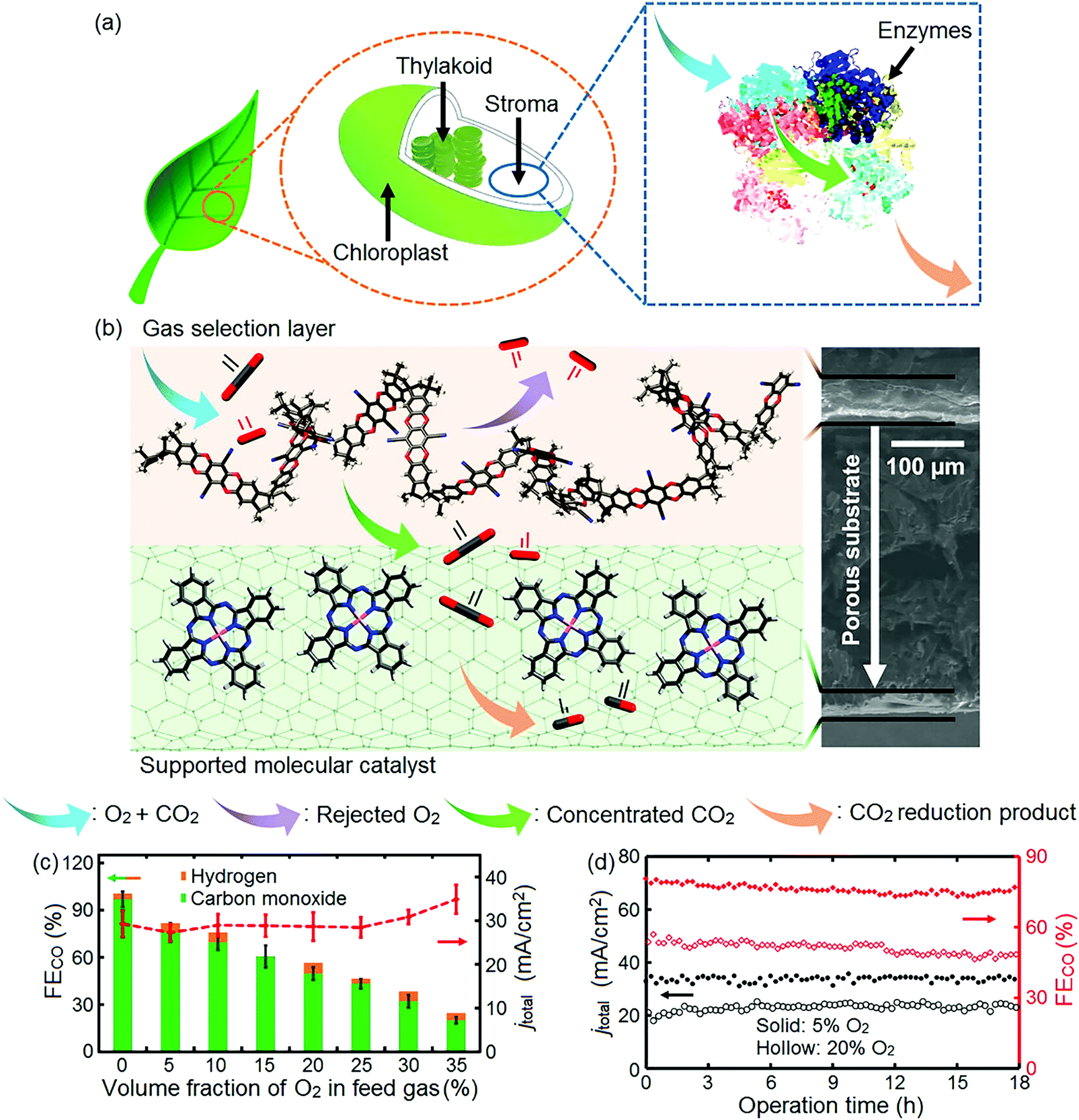
Inspiration for the design of electrocatalysts and devices can be derived from nature, which is full of hierarchically scaling structures. This critical review demonstrates the scope of a systematic, nature-inspired chemical engineering approach (NICE) across all scales, and emphasizes the difference between bio-imitation and bio-inspiration in design. The bio-inspired approach does not aim at replicating the exact details of an enzyme's active site or the veins of a leaf by copying seemingly useful features; instead, it thoroughly investigates the structural and functional characteristics of biological organisms to generate innovative and better performing electrocatalysts and devices for the same applications. Examples of bio-inspired electrocatalysts for key energy conversion reactions, as well as nature-inspired electrochemical devices are provided in the following sections.
2. Nature-inspired, integral design of electrocatalysts and devices
With advances in computational tools and material synthesis techniques, the creation of electrocatalysts has become a progressively more sophisticated craft, achieving optimal sizes of nanoparticles, high surface area, and accurate control of crystal facets and the specific position of individual catalytic atoms within the crystal lattice to increase the number of active sites.105However, all electrocatalyst designs discussed hitherto focus on alterations at the nano-scale only. To further improve on the properties and use of these electrocatalysts in devices, a new methodology for hierarchical catalyst design and implementation, which considers all scales, is pivotal. Not only at the nanoscale, but also across larger scales, inspiration can be drawn from nature, which provides us with numerous examples of intrinsically scaling, hierarchical structures and includes bio-catalysts for the same electrochemical reactions as those employed in electrochemical devices. Thorough examination of the structure and dynamics of natural systems can reveal key mechanisms that underpin desired properties, such as efficiency, scalability and robustness. For example, the branching structure of trees, the vascular network and mammalian lungs is not arbitrary, but consists of similarly repeated divisions across many length scales; the specific geometric properties of these natural transport networks result in facile scaling, as well as in extraordinary overall thermodynamic efficiency, through the minimization of entropy production.101,106–111 At meso- to macroscales, hierarchical transport networks in nature obey fractal scaling relationships, some of which relate to Murray's law,112–115 or generalizations thereof, discussed in Section 3.1. Careful observation and characterization of geometrical and dynamic patterns in nature could, therefore, help us to discover commonalities. This analysis should be carried out beyond superficial appearances, by seeking underlying physico-chemical, mechanistic principles, while being conscious of how particular features might depend on the constraints of the natural environment – constraints that could differ in several ways from the context of an engineering application. This way to study and learn from nature is the basis for the nature-inspired chemical engineering (NICE) approach.106
One example illustrating a basis for nature-inspired design of chemical reactors is a typical tree (Fig. 1). The quest for process intensification is an important one in chemical reactor engineering, as multiphase catalytic reactors in particular are plagued by issues related to scale-up, efficiency and robustness. Addressing such problems requires integration of selective, stable catalysis and transport phenomena across scales, which trees resolve through their design. At the macro-scale, tree roots provide support, and extract water and nutrients from the soil, which are transported via its fractal network throughout its volume. The crown of the tree consists of ramified branches and twigs with increasingly smaller diameters following fractal, self-similar scaling. Twigs bear leaves employing a venation pattern at the meso-scale for efficient chemical transport, while, at the nano-scale, leaves contain molecular complexes to capture sunlight and convert CO2 into sugars and oxygen via photosynthesis, providing the essential nutrients for the growth of the tree. All scales, and the design at and between scales, matter.
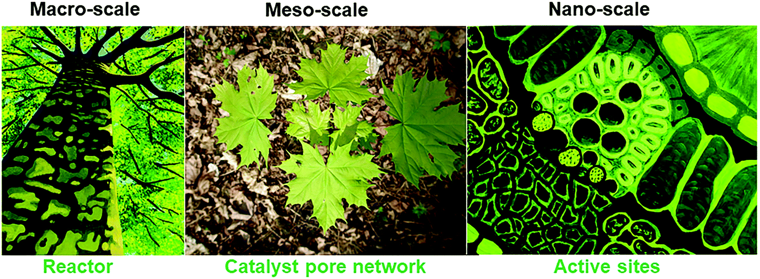 | ||
| Fig. 1 A tree as an example from nature to inspire the design of chemical reactors, from its scalable, fractal architecture of transport pathways at the macroscale, via the uniform distribution of channels at the mesoscale of the porous catalyst to the structure of the active sites at the nanoscale. Image of the tree (macro-scale) and active sites during photosynthesis (nano-scale) was reprinted with permission from ref. 116. Copyright 2010 American Chemical Society. | ||
The NICE approach we advocate and widely employ at the Centre for Nature Inspired Engineering (CNIE) at UCL in areas ranging from cancer immunotherapy to water purification, bio-separations, and the built environment, allows, in the context of this review's subject, for the design of bio-inspired electrocatalysts and electrochemical devices based on two fundamental mechanisms that are particularly effective in nature, namely, hierarchical transport networks to bridge length scales, and force balancing at individual scales. It should be noted that both principles are relevant to a much broader range of applications in heterogeneous catalysis and reaction engineering.
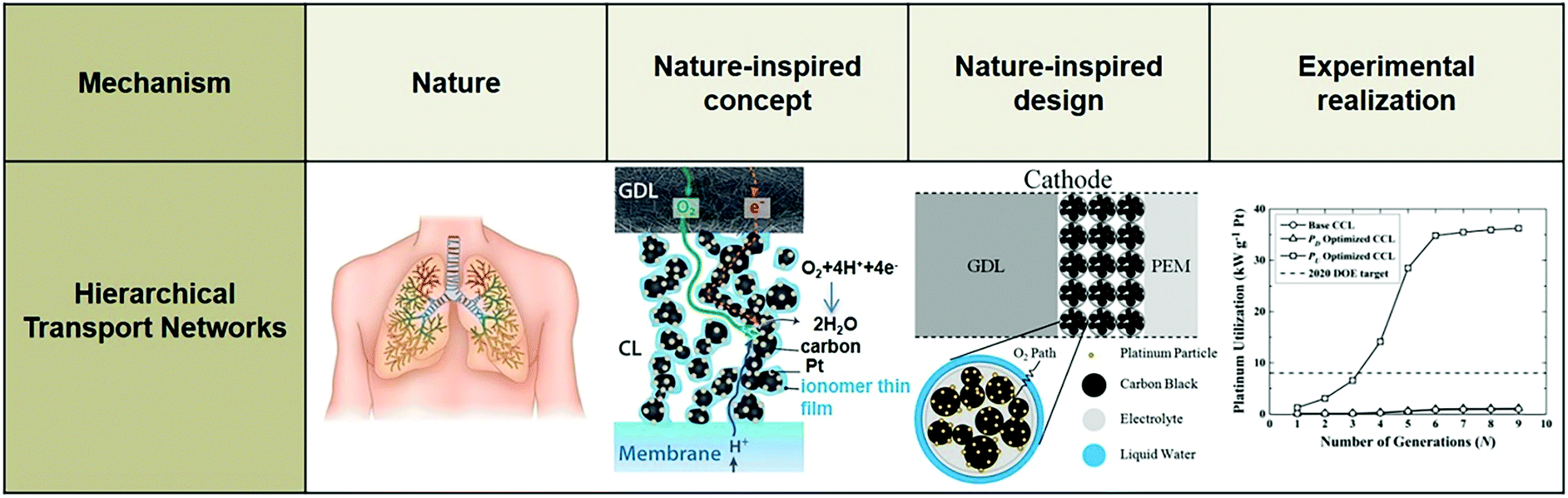
In terms of hierarchical transport networks, we capitalize on the unique structural characteristics of the lung to design and engineer flow fields for polymer electrolyte fuel cells (PEFCs). The NICE approach to design PEFCs will be discussed in more detail in Section 5.3, but Fig. 2 summarizes the methodology. The unique features of the lung (“Nature”) derive from its ability to bridge length scales and scale-up, irrespective of size, while providing uniform distribution of oxygen into the blood cells and minimizing thermodynamic losses across its structure; this is achieved by transitioning from a fractal tree of increasingly narrowing bronchi to a more uniform channel architecture in the acini, at a bronchiole size where the Péclet number is approximately 1, corresponding to a transition between convection-driven and diffusion-dominated gas transport (“Nature-inspired concept”). A mathematical model could then be developed and used in computer simulations, based on these characteristics of the lung, to calculate the required number of fractal generations in a fuel cell flow field to achieve uniform distribution of reactants (when Péclet ∼1) on the catalyst layer (“Nature-inspired design”), after which scalable, robust lung-inspired flow fields could be created by various manufacturing techniques, including a form of metal 3D printing, called selective laser sintering (“Nature-inspired design”). Lung-inspired flow field based PEFCs made out of stainless steel or printed circuit boards (PCBs) exhibited improved performance over commercial serpentine flow field based PEFCs (“Experimental realization”).
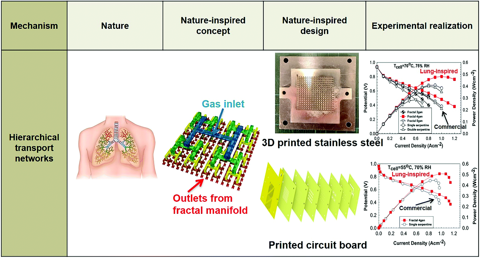 | ||
| Fig. 2 Systematic, step-by-step employment of the NICE approach for the design and engineering of lung-inspired flow fields for PEFCs. | ||
With regards to the catalyst itself, which this flow plate feeds, the local environment of the active site is crucial to its activity, selectivity, and stability. The NICE approach explores the nano-confinement effects induced by local curvature, as well as the impact of chemical and geometrical heterogeneity on transport in nanoporous materials and utilizes it in the design of the electrocatalytic layers. A hierarchically porous structure with a network of broad and narrow pores is required to reduce transport limitations and increase overall rates; nature-inspired catalyst design will be discussed in Sections 4 and 5.
This review discusses a range of examples pertaining to these two fundamental mechanisms. Other ubiquitous fundamental mechanisms employed by nature to underpin attractive properties, such as resilience and adaptability, fall outside of this review and will not be discussed here, however we see these as holding great promise in future electrochemical systems engineering. These mechanisms include dynamic self-organization and self-healing properties of natural systems, and the structure of natural networks (e.g. in ecosystems and metabolic networks), control mechanisms and modularity – in the CNIE, these two additional mechanisms are already applied to address a range of other engineering challenges, and the validation of the NICE approach will help to set the stage for applications in electrochemical devices and their operation.
In summary, nature's universal, fundamental mechanisms are an excellent guide to redesign processes and catalytic materials, as they epitomize efficient, robust, and scalable hierarchical structures. However, equally important is the appreciation that almost any optimization problem, in nature and technology, is a constrained multi-objective optimization challenge; the differences in constraints need to be considered when adopting natural mechanisms to solve engineering problems. Here, we will discuss systematically when and how a thorough scientific investigation into natural processes and materials in relation to their function and structure can provide nature-inspired solutions for the design of electrocatalysts and devices.
3. Ways to connect nature to electrocatalyst design: inspiration vs. imitation
Thus far, the majority of research on the development of new electrocatalysts that turns to nature for inspiration is, in fact, based on much more direct bio-imitation, which mimics isolated features of biological or non-biological structures, leading to low activity and durability issues.101,110,111 We use the term bio-imitation to differentiate this direct approach to the systematic, stepwise, nature-inspired engineering methodology discussed in Section 2. Even though the actual mechanistic features or physical processes that govern the biological system are neglected, there are successful examples of bio-imitating electrocatalysts.101,110,111A series of electrocatalysts for hydrogen evolution and oxidation reactions were synthesized, following two strategies: (i) utilization of the active metal center of NiFe or FeFe hydrogenase as catalyst for electrochemical reactions (bio-imitation);117–120 and (ii) immobilization of enzymes on carbon support (bio-integration).121 Based on the first bio-imitation approach, metallic complexes (such as FeFe or NiFe) using the same metal sites of the active center of hydrogenases were synthesized, and demonstrated activity toward the hydrogen evolution reaction.117–120,122 One of the most effective catalysts produced by this approach was a mono-Ni bis-diphosphine complex123 based on the characteristics of FeFe hydrogenase. Even though it could catalyze the hydrogen oxidation and evolution reaction in organic solvents123,124 or acidic aqueous solutions (pH = 0–6),125 its high sensitivity to oxygen hinders its use in fuel cell systems.126
To circumvent this issue, a bio-integration approach was used with the adsorption of hydrogenase on gold and graphite electrodes.127–130 Even though this method contributed to the understanding of the catalytic activity of the enzymes, its major drawback was the weak stability of most hydrogenases to oxygen.131 A decrease in activity was observed over time as a result of the slow modification of the active site by residual traces of O2 and protein reorientation at the interface.129 Additionally, the large size of the metalloenzyme (∼6 nm) dictated the development of high surface area electrodes (such as carbon nanotubes) with high loading to achieve current densities comparable to those of Pt electrocatalysts.128
While the above examples introduce interesting catalysts and provide useful insights, it is evident that the difference in context between nature and technology, such as in size, medium, and position of active metal center, is not accounted for. Doing so could help to make further progress, because a genuinely nature-inspired approach is based on the mechanistic understanding of fundamental mechanisms underlying desired traits, without necessarily copying or directly utilizing the source of inspiration; these mechanisms are incorporated into the design and synthesis of artificial systems encompassing the traits of the natural model.101,109–111 In the following sections, we provide examples of bio-inspired designs of electrocatalysts for key electrochemical reactions for energy conversion at the nanoscale (Fig. 3) and of electrochemical devices at larger scales, including our NICE approach in the design of lung-inspired flow fields for PEFCs.
 | ||
| Fig. 3 Example of a nature-inspired design for electrocatalysts based on the structure and function of metalloenzymes. | ||
3.1 Nature-inspired electrocatalysts for the oxygen reduction reaction
The overall oxygen reduction reaction (ORR) on an electrocatalyst is a multi-electron, multi-step reaction involving several reaction intermediates. The distinction between the different mechanisms of the ORR relies on the number of proton-coupled electron transfer steps preceding the breaking step of the O–O bond.132 A four-electron (4e−) route is desirable to directly produce H2O (in acidic medium) and OH− (in alkaline medium) as the final products; depending on the electrocatalytic properties, a two-electron (2e−) sub-route can be included producing H2O2 (in acidic medium) and HO2− (in alkaline medium) as the intermediate species (Table 1).27,59,132–140| ORR pathway | Acidic medium | Alkaline medium |
|---|---|---|
| 4e− | O2 + 4·H+ + 4·e− → 2·H2O | O2 + 2·H2O + 4·e− → 2·OH− |
| 2e− | O2 + 2·H+ + 2·e− → H2O2 | O2 + H2O + 2·e− → HO2− + OH− |
| H2O2 + 2·H+ + 2·e− → 2·H2O | H2O + OH2− + 2·e− → 3·OH− |
The fundamental understanding of the ORR mechanism is still unclear, due to the complexity of its kinetics;132 the rate determining step, sequence of electron and proton additions,141 as well as adsorption of intermediates are still under debate. The rate determining step is considered to be the first electron transfer from the topmost electrode surface to the adsorbed molecular oxygen (O2ads),135,142–145 while the adsorption of intermediate species, such as oxygen (O*) and hydroxyl (OH*) radicals, is suggested to be the crucial step of the ORR mechanism on metallic catalysts.136,146,147 For metals that bind oxygen too strongly, the reaction rate is limited by the removal of the adsorbed O* and OH* species. For metal surfaces that bind oxygen too weakly, the reaction rate is limited by the dissociation of O2, or, more likely, the transfer of electrons and protons to adsorbed O2.135,136
Successful bio-imitation approaches for the design of electrocatalysts for the oxygen reduction reaction have been employed, mimicking the active metal center of enzymes coordinated by carboxyl, amine, thiol, and imidazole groups of the amino acid side chains.148 Metallophthalocyanines,149–158 and metalloporphyrins149,150,159–169 have been extensively investigated as non-precious metal electrocatalysts for ORR, even though they lack long-term stability in the harsh environment of a fuel cell.159,170,171
Iron phthalocyanines catalyze the direct reduction of oxygen to water via a four-electron pathway, promoting scission of the O–O bond.149,150 On the contrary, the ORR activity of metalloporphyrins depends on whether their meso-positions are occupied by aryl, pyridyl, or alkyl substituents.168,169 For example, cobalt metalloporphyrins adsorbed on graphite electrodes without meso substituents demonstrated two-electron oxygen reduction, whereas the adsorbed cobalt porphyrins with meso substituents directly oxidized oxygen to water via a four-electron pathway.169 This catalytic behavior was attributed to the spontaneous formation of van der Waals dimers facilitating the reduction of oxygen to water via four electrons.169 The interaction between the cobalt centers of the porphyrin dimer and the atoms of oxygen leads to a transition state where the bridging oxygen molecule is activated, accepting four electrons from the graphite electrode, which causes the scission of O–O bond.169
Based on these attractive activity characteristics, metal organic networks employing well-defined metal surfaces decorated with porphyrins or phthalocyanines have been synthesized via supramolecular chemistry.148,155,166,167,172,173 Iron phthalocyanines adsorbed on the surface of Au(111) enhanced its ORR activity in alkaline media (∼0.030 V Tafel slope), allowing the direct reduction of oxygen to water via a four-electron route with cleavage of the O–O bond, in contrast to the observed oxygen reduction via a two-electron route in the case of bare Au(111) surface.155 Additionally, chemisorbed cobalt porphyrin on the surface of Au(111) increased its ORR activity in acidic media,166,167 demonstrating an increase of the reductive current.166,167 Despite these promising preliminary results, these bio-imitating catalysts are in early development and challenges concerning long-term stability and activity, as well as the tuning of adsorbate–substrate interactions have to be resolved.174
Recently, mononuclear iron porphyrins with distal basic residues (i.e., pyridine, aliphatic and dibenzyl aromatic amines) imitating the proton transfer pathways and hydrogen bonding groups in cytochrome c oxidase149,175–179 demonstrated high selectivity (greater than 90%) and reactivity (rate constant greater than 107 M−1 s−1) for ORR at pH = 7 when adsorbed on an edge-plane graphitic electrode.180 The measured rate constant of oxygen reduction was approximately two orders of magnitude higher than the heme/Cu complexes,181–186 suggesting that the distal basic residues stabilize the FeIII–OOH intermediate species and enable heterolytic cleavage via protonation of their distal oxygen, promoting a four-electron ORR route.180
Another promising example of a bio-imitating, porphyrin-based ORR electrocatalyst mimicking the active site of oxygen-activating heme-containing enzymes, such as cytochrome c oxidase, is an axial-imidazole coordinated iron porphyrin, covalently grafted on multi-wall carbon nanotubes (MWCNTs).187 This electrocatalyst exhibited high activity and stability in acidic and alkaline media; its half-wave potential (E1/2) in both media was ∼38 mV (E1/2 ∼ 0.88 V vs. NHE, 0.1 M HClO4) and ∼47 mV (E1/2 ∼ 0.922 V vs. NHE, 0.1 M KOH) higher than the commercial Pt/C (E1/2 ∼ 0.842 V and ∼0.875 V vs. NHE in acidic and alkaline media, respectively). Koutecky–Levich plots revealed a four-electron oxygen reduction route, with the production of a minimal amount of hydrogen peroxide (less than 1% H2O2). The stability of this bio-imitating electrocatalyst was evaluated via US DoE's accelerated test protocol, demonstrating a ∼14 mV loss in E1/2, which was less than half of the decrease exhibited for commercial Pt/C (∼37 mV loss) after 10![[thin space (1/6-em)]](https://www.rsc.org/images/entities/char_2009.gif) 000 continuous cycles between 0.6 V and 1 V (vs. NHE) in an oxygen saturated acidic solution (0.1 M HClO4).187 The high activity and stability of this electrocatalyst was attributed to its low half-wave potential value for ORR and, hence, the associated low amount of H2O2 produced, insufficient to deactivate and degrade this electrocatalyst.187
000 continuous cycles between 0.6 V and 1 V (vs. NHE) in an oxygen saturated acidic solution (0.1 M HClO4).187 The high activity and stability of this electrocatalyst was attributed to its low half-wave potential value for ORR and, hence, the associated low amount of H2O2 produced, insufficient to deactivate and degrade this electrocatalyst.187
Furthermore, the ORR activity of metalloporphyrins is affected by their structure and the distance between their active metal centers.188,189 Hence, crystalline porous materials such as metal organic frameworks (MOFs) or covalent organic frameworks can be used as scaffolds to accurately control the structure of metal–metalloporphyrin frameworks,190 resulting in efficient ORR electrocatalysts with high surface area and porosity. However, their major disadvantage is their low electronic conductivity and long-term stability,191 and, thus, further research is needed to effectively utilize these electrocatalysts in fuel cells.
Metallocorroles have also attracted attention as electrocatalysts for the ORR due to their high activity and tunable structure.191–199 Metallocoroles are tetrapyrrolic macrocyclic compounds with one less carbon atom than porphyrins.191 Their tri-anionic charge stabilizes the metal center and affects the chemistry of the chelated transition metal ions, resulting in low valent corrole-transition metal complexes, which are much more reactive than their porphyrin analogs.191
Several transition metal complexes with brominated corrole (β-pyrrole-brominated 5,10,15-tris-pentafluorophenyl-corrole, M(tpfcBr8), where M = Mn, Fe, Co, Ni, and Cu) adsorbed on a high surface area activated carbon (BP2000) have been investigated as electrocatalysts for ORR in alkaline media.194 Iron- and cobalt-based brominated corroles exhibited the highest activity following a four-electron pathway for the direct reduction of oxygen to water, similar to the ORR activity of commercial Pt/C (20 wt% Pt) tested under the same conditions.194 In acidic media, the ORR activity increases in the order of Co > Fe > Ni > Mn > Cu, with brominated cobalt-corrole demonstrating the best activity with an onset potential ∼80 mV lower than commercial Pt/C (20 wt% Pt).199 In addition to the metal center of the brominated corrole, its ORR activity is suggested to depend on the support, since adsorption of metallocorroles on activated carbon or carbon nanotubes decreases the reaction overpotential.191,199–201 Further research is needed to fully comprehend this phenomenon.
Despite these promising ORR activity results, the incorporation of these bio-imitating electrocatalysts into PEFCs remains a great challenge. Their activity and stability have been evaluated only at RRDE level, and not in a membrane electrode assembly under harsh fuel cell conditions. Thus far, these electrocatalysts demonstrate poor stability and improved catalyst designs would have to be introduced to meet the requirements for practical PEFC applications.202 As this review is not focused on bio-imitating electrocatalysts, readers are referred to other published reviews for more information on this topic.148,191,202,203
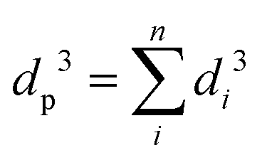
Since the reduction and evolution reactions occurring in a fuel cell comprise three phases (gas/liquid/solid), electrocatalysts with a hierarchical porous structure are desirable to promote mass transfer and improve utilization of reactant. To improve the design of electrocatalysts, the hierarchical pore networks utilized by biological organisms (such as trees, other plants and their leaves, etc.) were used as a source for inspiration. These organisms grow obeying power laws that are generalizations of Murray's law, utilizing precise diameter ratios to connect pores from macro- to meso- and micro-scale, which results in the minimization of transport resistance and fluent transfer throughout the network.113,204
According to Murray's law, the cube of the diameter of the parent vessel (dp) is equal to the sum of the cubes of the diameters of the daughter vessels (di, i = 1…n, where n is the number of macro-, meso-, or nano-pores in each particle) at each level of bifurcation:109–111
 | (1) |
A layer-by-layer, evaporation-driven self-assembly process utilizing a microporous material (ZnO, in this example) as the primary building block under ambient conditions is employed for the synthesis of these so-called “Murray materials”.205 The synthesis procedure of these materials is a tedious, multi-step process, since various reaction conditions are utilized to produce a combined micro-, meso-, and macro-porous ZnO (Fig. 4). Microporous ZnO is prepared in inert atmosphere using a mixture of zinc acetylacetonate hydrate and oleylamine. Mesoporous ZnO nanoparticles (∼30 nm size) are synthesized using the same method with additional calcination at ∼290 °C.
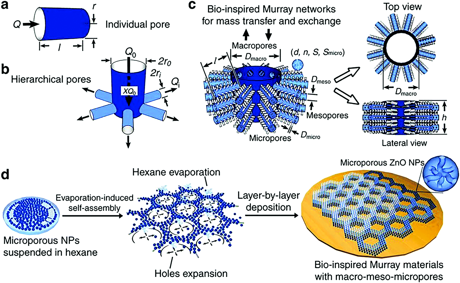 | ||
| Fig. 4 (a) Individual pore model; (b) hierarchical pore model with a parent pipe connecting with daughter pipes; (c) hierarchical porous network model of the macro-meso-micro-porous materials: d is the diameter of nanoparticles, n is the average number of micropores within a single nanoparticle, S is the specific surface area of all the nanoparticles, Smicro is the surface area of the micropores, dmicro and dmeso are the diameters of micro-pores and meso-pores, respectively; (d) fabrication process of the “Murray materials” via layer-by-layer evaporation-driven self-assembly of nanoparticles. Reprinted with permission from ref. 205 (Creative Commons Attribution 4 International License). | ||
To prepare the micro-, meso-, and macro-porous material, micro- and meso-porous ZnO particles are dispersed separately in a volatile solvent (e.g. hexane, ethanol). The first microporous layer is created by drop-casting of microporous ZnO solution on a silicon wafer and evaporation of the volatile solvent. Then, mesoporous ZnO solution is drop-casted on the already formed ZnO microporous layers.
The concentration of ZnO in solution directly affects the evaporation rate of the solvent. At low ZnO concentration (∼0.03 mg mL−1), the nanoparticles are self-assembled into isolated islands; small macropores gradually appear as the ZnO concentration is increased (∼0.06 and 0.12 mg mL−1) due to the enhanced nucleation and restricted expansion of the holes. Further increase in ZnO concentration (∼0.5 mg mL−1) leads to a porous network with ZnO nanoparticles forming packed structures.205
These initial experimental results are very promising; however, the general applicability of Murray's law to the synthesis of a wide range of materials for various applications has to be thoroughly investigated. The synthesis method advocated for hierarchical Murray ZnO may not be feasible or appropriate for different materials; hence, alternative synthesis methods should be explored, such as templating, crystallization, the Kirkendall effect, etc.101
Recently, Murray-like cobalt supported on nitrogen doped carbon (Co–N–C) electrocatalysts for oxygen reduction and evolution, and hydrogen evolution reactions in alkaline medium were synthesized using Prussian blue analogue (PBA) as a precursor.206 Pyrolysis was used instead of the layer-by-layer drop casting method (Fig. 5). The 3D cubic porous network of PBA imitated the hierarchical structure obtained by Murray's law, while PBA acted as the carbon, nitrogen, and cobalt source, and polyvinyl pyrrolidone (PVP) as the surfactant. After thermal treatment (pyrolysis at 900 °C in inert atmosphere), a spherical porous assembly of Co nanoparticles covered by nitrogen doped graphitic carbon was produced. Acid leaching (2 M HCl solution) was employed to remove the unstable species and optimize the porosity of the material, increasing its electrochemically active surface area (ECSA) as demonstrated by double layer capacitance measurements (∼8 and ∼7 mF cm−2 for acid and non-acid treated Co–N–C, respectively).206 Physicochemical characterization (X-ray diffraction (XRD), Raman and X-ray photoelectron spectroscopy (XPS), scanning (SEM) and transmission (TEM) electron microscopy) of the material post acid treatment demonstrated that its structure remained intact, while the composition and valence states of Co, N, C, Zn, and O at the surface of the electrocatalyst were similar to the ones before the acid modification step.
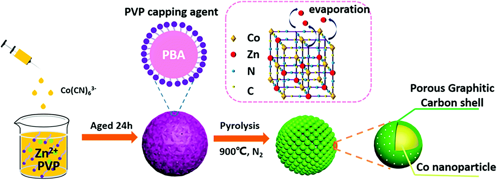 | ||
| Fig. 5 Schematic of the synthesis and the structure of the spherical Murray-type Co–N–C electrocatalysts. Reprinted with permission from ref. 206. Copyright 2019 American Chemical Society. | ||
As a result, the acid treated Murray-type Co–N–C materials exhibited similar ORR activity (diffusion-limited current density of 5.7 mA cm−2) and electron transfer (∼4e−) to commercial Pt/C in alkaline solution (Fig. 6a). In the case of OER and HER (Fig. 6d), acid treated Murray-type Co–N–C displayed low onset overpotentials of ∼150 and ∼350 mV, corresponding to the hydrogen evolution reaction and oxygen evolution reaction in alkaline solution (1 M KOH), respectively, highlighting its potential to be used in overall water splitting with a total splitting voltage of 1.73 V.206 Finally, these acid treated Murray-type electrocatalysts exhibited immunity to methanol (2 M) compared to commercial Pt/C (Fig. 6b), as well as higher stability than non-acid treated Murray-type and commercial Pt/C, with ∼99% retention at 0.5 V (vs. RHE) after a ∼6 h continuous chronoamperometric measurement, compared to ∼93% and ∼84% retention for non-acid treated Murray-type Co–N–C and commercial Pt/C, respectively (Fig. 6c).206 Hence, the ORR activity of these electrocatalysts is affected by N species, whereas the OER and HER activity is determined by the Co species, providing more sites for the adsorption of H* and OH* radicals.59,207,208 Despite the low water splitting performance of Murray-type Co–N–C electrocatalyst compared to literature values,209 these initial results demonstrate the potential of Murray-type electrocatalysts with optimal porous structure to be utilized in triphase electrochemical reactions.
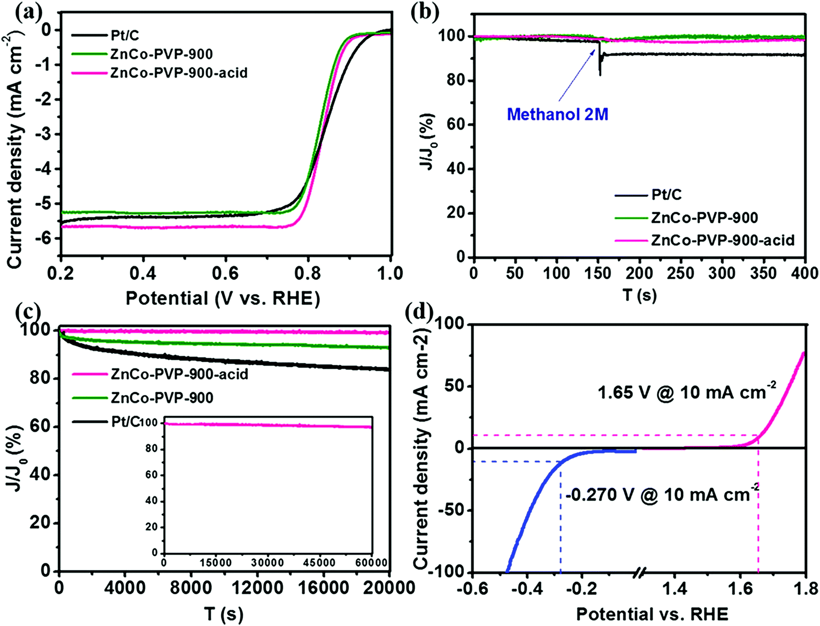 | ||
| Fig. 6 (a) Linear sweep voltammetry (LSV) of acid treated Murray-type Co–N–C (ZnCo-PVP-900-acid), non-acid treated Murray-type Co–N–C (ZnCo-PVP-900), and commercial Pt/C in O2 saturated 0.1 M KOH solution at a sweep rate of 5 mV s−1 and 1600 rpm; (b) chronoamperometry curves of ZnCo-PVP-900-acid, ZnCo-PVP-900, and Pt/C for the ORR at 0.5 V vs. RHE by introducing 2 M methanol into the electrolyte at 150 s; (c) chronoamperometry curves of ZnCo-PVP-900-acid, ZnCo-PVP-900, and Pt/C at 0.5 V vs. RHE for 20000 s; the inset is the curve of ZnCo-PVP-900-acid at 0.5 V vs. RHE for 60000 s; (d) LSV of ZnCo-PVP-900-acid in 1 M KOH solution at a sweep rate of 10 mV s−1 for the HER and OER. Reprinted with permission from ref. 206. Copyright 2019 American Chemical Society. | ||
Moreover, inspiration for the design of new electrocatalysts for ORR can be derived from the active metal center of cytochrome c oxidase and laccase, which comprises iron and copper ion complexes.210,211 However, directly mimicking the Cu2+ or Fe3+ complexes is not a fruitful strategy, as it leads to low activity, due to the absence of mediators for the transfer of electrons and the steric variation of the coordination structures after these complexes are attached onto the electrode.212
As an example of effective tuning of the electron density of such an active site (Cu2+ based), copper nanocomposites (CPG) were synthesized via the pyrolysis of a mixture of graphene oxide (GO) and Cu(phen)2 (Cu2+1,10-phenanthroline).212 The electron density of Cu2+ sites was tuned by the electron donation effect from Cu0 of copper nanoparticles and nitrogen ligand incorporated into graphene. The electron transfer in CPG was increased via the electronic connection of Cu2+ and nitrogen, as well as Cu2+ and Cu0 in graphene, resulting in enhanced ORR activity.212 Pyrolysis temperature also affected the activity of CPG, with 900 °C being the optimum in this study.212 The exhibited ORR onset potentials of ∼0.85 and ∼0.98 V (vs. RHE) and Tafel slopes of 71 and 49 mV dec−1 in 0.5 M H2SO4 and 1 M KOH, respectively, were similar to commercial Pt/C, demonstrating the high activity of this catalyst.212
3.2 Nature-inspired electrocatalysts for the oxygen evolution reaction
The oxygen evolution reaction (OER) is the reverse of the ORR: water is oxidized to oxygen via a 4e− pathway (Table 2).213–217 The mechanism of the OER is sensitive to the structure of the electrode surface.| OER pathway | Acidic medium | Alkaline medium |
|---|---|---|
| H2O + * → OH2* | OH− + * → OH* + e− | |
| OH2* → OH* + H+ + e− | OH* + OH− → H2O + O* + e− | |
| OH* → O* + H+ + e− | O* + OH− → OOH* + e− | |
| H2O + O* → OOH* + H+ + e− | OOH* + OH− → * + O2 + H2O + e− | |
| OOH* → O2 + * + H+ + e− | ||
| Overall reaction | 2·H2O → O2 + 4·H− + 4·e− | 4·OH− → O2 + 2·H2O + 4·e− |
The symbol “*” represents a surface with one oxygen vacancy site in the topmost layer, while the symbols “OH2*”, “OH*”, “O*”, and “OOH*” represent the surface with the corresponding chemisorbed species residing in the oxygen vacancy site.59 The complete OER mechanism in acidic medium consists of four oxidation steps, in each of which a proton is released into the electrolyte. Water is first adsorbed onto the surface of the oxygen vacancy site, forming “OH2*” species. “OH2*” then undergoes two subsequent oxidation reactions to form “O*”, which reacts with another water molecule to form an “OOH*” intermediate. In the last step, oxygen is released from “OOH*”.59
The oxidation of water to oxygen in nature is catalyzed by the oxygen-evolving complex (OEC) in photosystem II, located within the thylakoid membranes of plants, algae, and cyanobacteria.218–220 Its active site responsible for water oxidation is the oxygen-evolving complex, which consists of four manganese ions and a calcium ion (Mn4CaO5) surrounded by a protein.219–222 This complex has a sophisticated structure, in which a Mn3CaO4 heterocubane is tethered to a fourth manganese ion via a μ-oxo bridge and a corner oxo-attachment.223–225 Even though the oxygen-evolving complex is still not fully understood at mechanistic level, metal-based clusters with cubane cores have already been synthesized as efficient catalysts for oxygen evolution reaction, imitating the Mn4CaO5 active site of photosystem II.221,224,226–228 To improve the design of these bio-imitating electrocatalysts, fundamental understanding of the OER mechanism by oxygenic multi-metallic clusters is required, along with a significant improvement of their stability under the harsh oxidizing conditions of OER.229,231,232 The approach that nature utilizes to circumvent the oxidative degradation of photosystem II by continuously replacing and repairing the damaged protein subunit220,229 in its structure cannot be applied in these artificial electrocatalysts.
The state-of-the-art electrocatalysts for the OER are ruthenium (RuO2) and iridium oxide (IrO2), but their high cost prohibit their application at large scale.230 Hence, extensive research is conducted on the synthesis and design of efficient and cost-effective electrocatalysts based on transition metals and layered double hydroxide materials.213,231–244 The design of new electrocatalysts for OER is focused on three scale levels: (i) at the atomic scale, the alteration of oxidation state,245 coordination,246,247 electron density,245 and composition of metal composites245,248 leads to an improvement of their electronic structure and an increase in OER activity; (ii) at the nano-scale, different material combinations (such as metal oxides),249,250 chalcogenide,249 boride,251 nitride,252 phosphide250 supported on nanostructures (e.g. nanowires,253,254 nanosheets,251,254 nanotubes255,256) have increased activity toward OER due to their high surface area and number of active sites; and (iii) at the meso-scale, the creation of a porous architecture of the support can enhance mass transport of the electrolyte, improving the activity and conductivity of the electrocatalyst.257
The structure of a leaf has served as a source of inspiration for the design of a 2D/1D cobalt oxide (CoOx) electrocatalyst (Fig. 7).258 Each leaf has a 2D morphology with optimized surface area, favoring light absorption and surface reactions, while the presence of 1D, hollow tubular structures under the leaf facilitates the transport of nutrients and water to each leaf.258 The leaf-inspired CoOx electrocatalyst consists of CoOx nanosheets (100–200 nm average diameter and 20–50 μm length) in a nanotube (200 nm average diameter, 20 μm length), which was synthesized via in situ etching of a Cu2O nanowire template and regrowth of thin CoOx nanosheets on the surface of the template.258 Hence, the structure of the CoOx electrocatalyst is improved across different scales; at the atomic scale, the presence of Co2+ in octahedral symmetry increases electron transfer, while the high surface area (∼371 m2 g−1) of CoOx nanosheets and 3D porous framework of CoOx nanotubes provide a high number of active sites and increased ion transport, respectively.258 The leaf-inspired CoOx electrocatalyst demonstrated an onset potential of ∼1.46 V (vs. RHE) similar to commercial IrO2, a current density of ∼51 mA cm−2 at 1.65 V (vs. RHE) and a Tafel slope of 75 mV dec−1. However, its stability is a concern, since a ∼35% loss in its current density (1.5 mA cm−2 initial current density at 1.5 V vs. RHE) was observed after 2 h of operation in an electrolysis cell.258
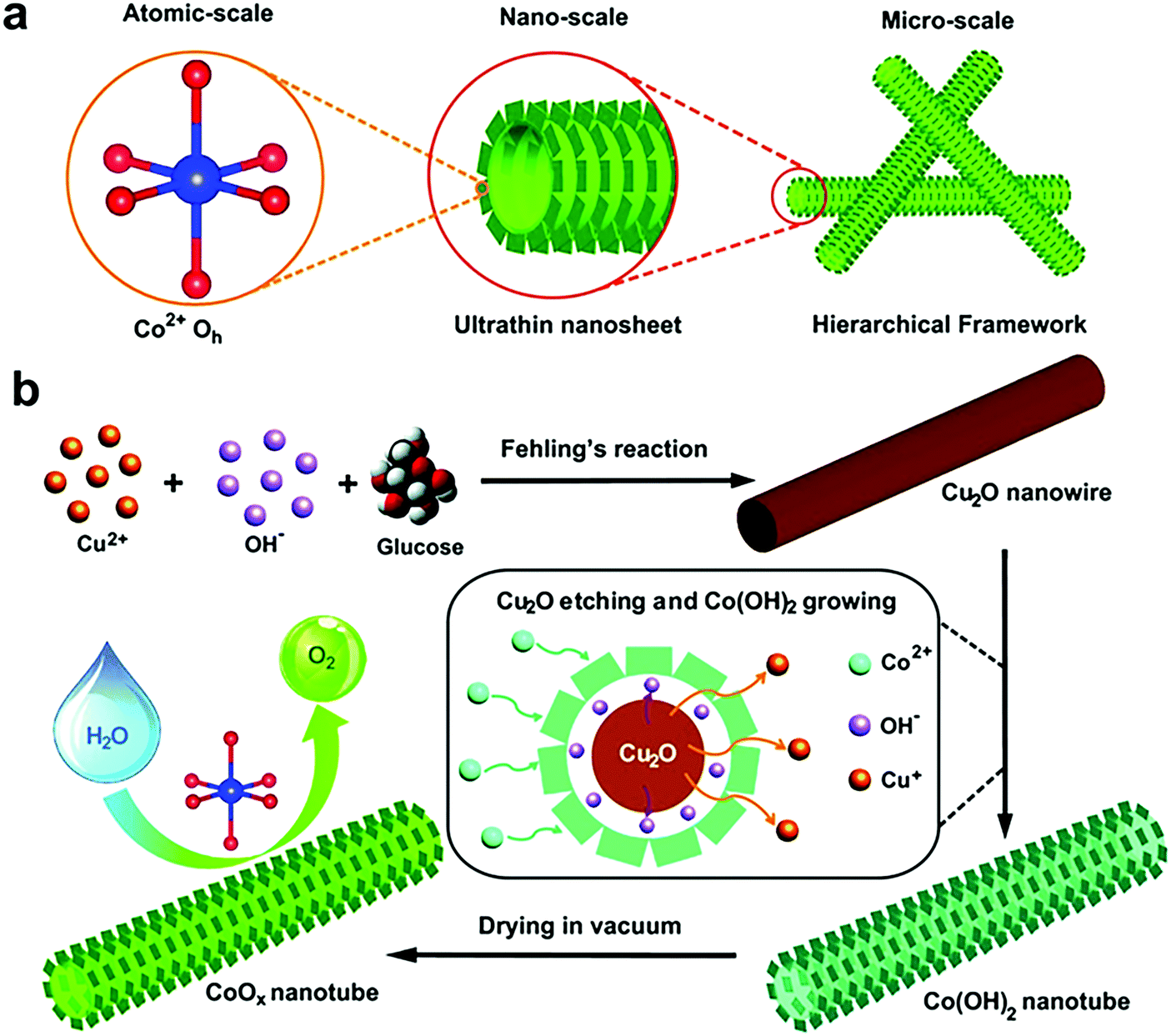 | ||
| Fig. 7 (a) Schematic illustration of the design of hierarchical CoOx nanosheet/nanotube structures; (b) synthesis procedure of the hierarchical CoOx nanosheet/nanotube structures, including the in situ growth of Cu2O nanowire templates, etching of the nanowire templates and regrowth of ultrathin Co(OH)2 nanosheets from the original nanowire template surface, and dehydration to form a CoOx nanosheet/nanotube structure. Reprinted with permission from ref. 258 (Creative Commons Attribution 4 International License). | ||
3.3 Nature-inspired electrocatalysts for hydrogen oxidation and evolution reactions
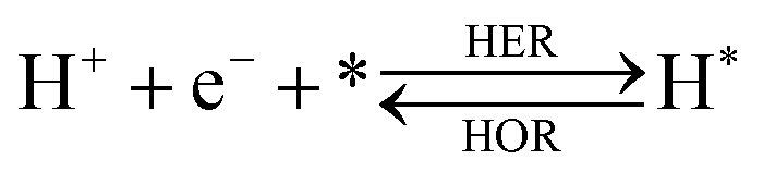
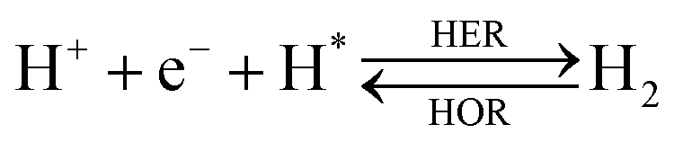
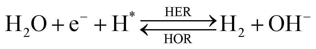
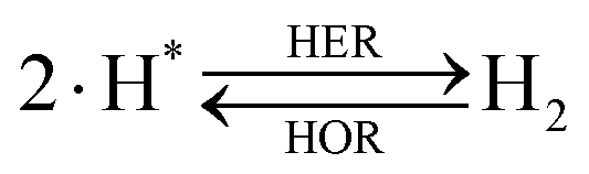
The overall reactions for hydrogen oxidation (HOR) and evolution (HER) reactions involve either protons in acidic media or hydroxide ions in alkaline media (Table 3).59,259,260 The first step of the reaction mechanism always involves the adsorption of a H intermediate on the electrode surface via a proton and electron transfer from the acid electrolyte and the surface of the electrode, respectively.| HER/HOR pathway | Acidic medium | Alkaline medium |
|---|---|---|
| Volmer |
|

|
| Heyrovsky or |
|
|
| Tafel |
|

|
| Overall reaction |
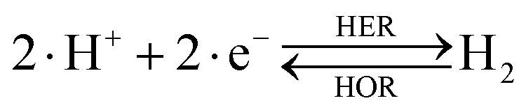
|
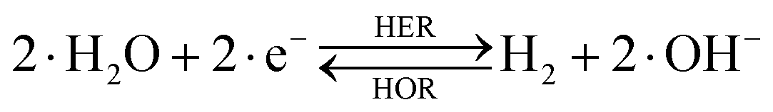
|
In acidic media, H+ is the proton source for the initial Volmer step, whereas, in alkaline media, H2O constitutes the proton source producing OH− after electron transfer. Recently, it was suggested that the Volmer step of the HOR/HER is the rate determining step for noble metals.260
There are two different reaction routes for the final step, determined by the Tafel slope values from polarization curves.259 The Heyrovsky reaction, in which the adsorbed hydrogen (H*) combines with an electron transferred from the electrode surface and a proton from the electrolyte to form hydrogen; or the Tafel reaction, in which two adsorbed hydrogen combine to form a hydrogen molecule (Table 3).
Pt based electrocatalysts are the state-of-the-art choice for hydrogen oxidation and evolution reactions in acidic media, as earth-abundant electrocatalysts cannot survive under these highly acidic conditions and exhibit similar activity to their Pt based counterparts.261,262 Even though the HER/HOR activity of Pt based electrocatalysts is decreased in alkaline media, their ability to catalyze these reactions at moderate overpotentials makes them the most efficient choice.261 The utilization of alkaline media for HER and HOR reactions enables the use of non-precious metal catalysts, such as heteroatom-doped carbon, transition metal oxides, sulfides, phosphides and their alloys,263–268 and molecular complexes based on porphyrin and corrole.150,264,269,270 Less attention has focused on non-precious metal electrocatalysts for the HOR.271–275 However, these non-Pt electrocatalysts suffer from poor kinetics and stability; modification of their electronic structure, crystal facets,265 composition variation,273,276 and surface area is required to optimize their hydrogen adsorption free energy, a key descriptor of their HOR/HER activity,14,277–279 and improve their catalytic performance and durability.
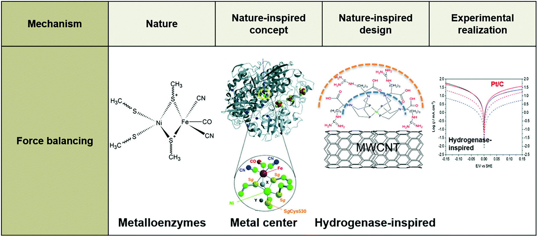
Inspiration for the design of new electrocatalysts for the HER and HOR can be derived from nature, and from hydrogenases, specifically. Hydrogenases are metalloenzymes widely used in nature for hydrogen evolution and oxidation in living systems, since they can achieve low overpotentials and high turnover frequencies employing Fe and/or Ni in their active site.126,280 Hydrogenases comprise three coordination spheres (Fig. 8).281,282 The inner coordination sphere consists of the metal center and the atoms bonded directly to it. The active site of FeFe hydrogenases has two iron atoms with CN− and CO ligands attached to each of these two atoms (Fig. 9), while the active site of NiFe hydrogenases has nickel ions deposited in cysteinate ligands, which are in contact with the dicyanocarbonyl iron center (Fig. 10).283–289 The most important ligand in this inner coordination sphere is azadithiolate, which plays an important role in hydrogen cleavage and proton transfer between the metal center and surface of the enzyme.283–289 The second coordination sphere contains functional groups incorporated into the ligand structure interacting directly with substrates bound to the metal during a reaction, but do not interact with the metal center. In hydrogenases, pendant bases are positioned in this coordination sphere to facilitate proton transfer between the metal center and the acid or base in the solution.281 The outer coordination sphere encompasses the remainder of the ligand structure and the solvent surrounding the catalyst.281
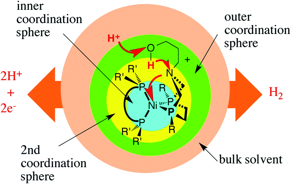 | ||
| Fig. 8 Conceptual partitioning of catalysts (hydrogenases) into inner, second, and outer coordination spheres. Reprinted with permission from ref. 281. Copyright 2014 American Chemical Society. | ||
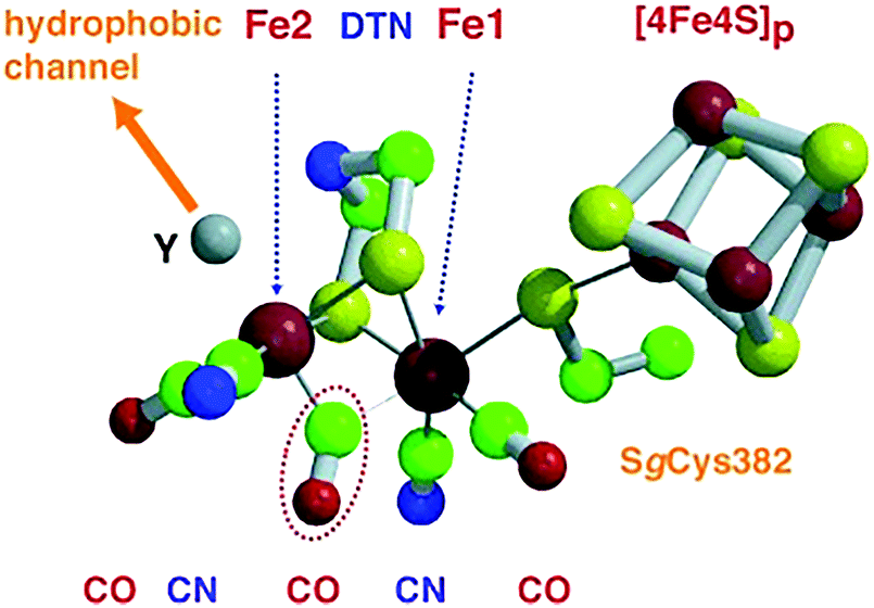 | ||
| Fig. 9 Catalytic site of FeFe hydrogenase. The CO ligand circled by a dotted line bridges the two iron atoms (Fe1 and Fe2) in the oxidized form and binds terminally to Fe2 in the reduced one. Di(thiomethyl)amine (DTN) bridges Fe1–Fe2, while the vacant axial coordination site (Y) of Fe2 atom binds a CO ligand and is close to a hydrophobic channel. Color code: iron = large red spheres, sulfur = yellow, carbon = green, nitrogen = blue, oxygen = small red. Reprinted with permission from ref. 283. Copyright 2002 Wiley-VCH. | ||
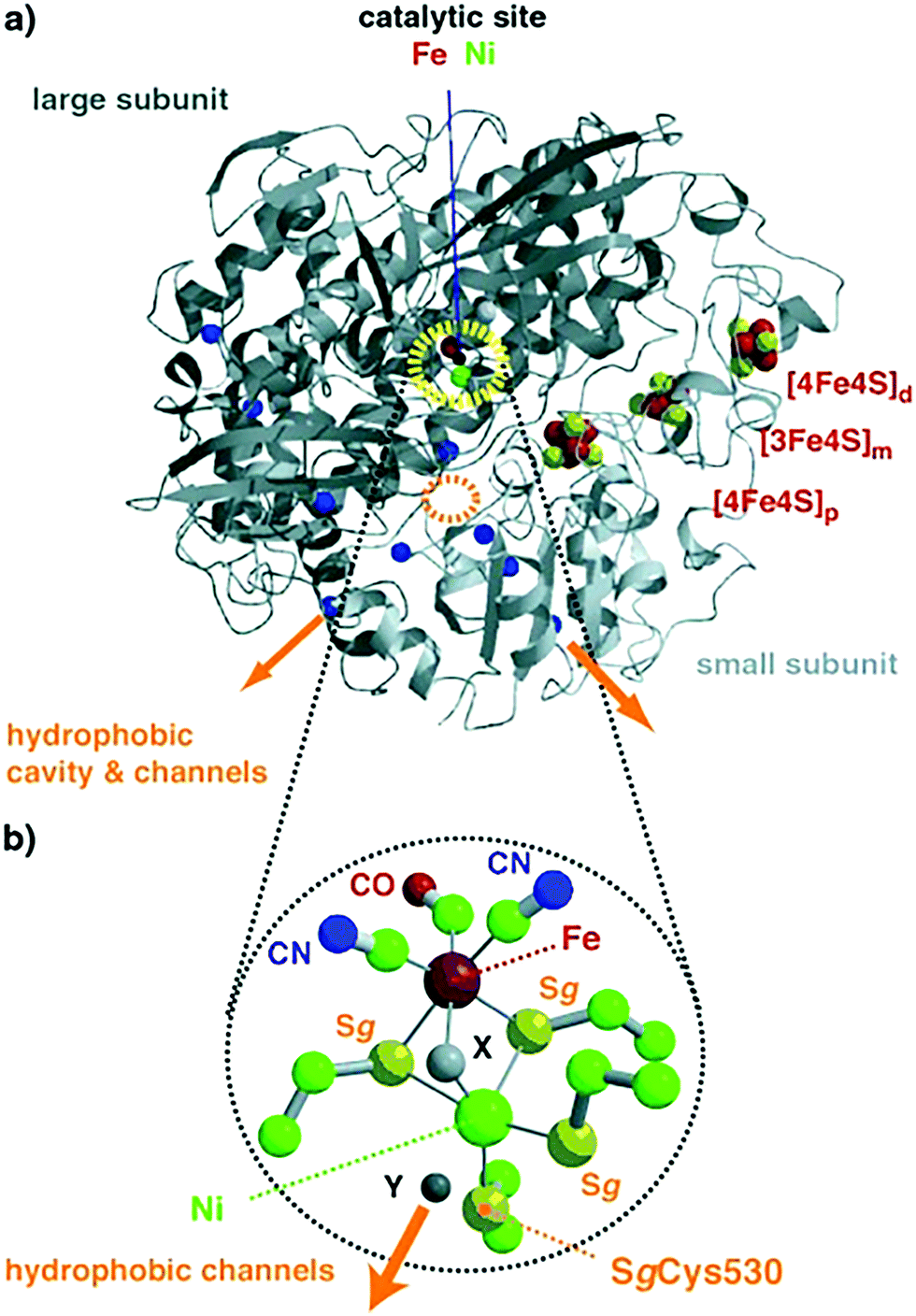 | ||
| Fig. 10 (a) Overall structure of NiFe hydrogenases; the polypeptide folds of the large and small subunits are colored in dark and light grey, respectively. The catalytic center of Ni–Fe (dotted yellow circle) and (b) iron–sulfur cluster atoms are pictured as spheres. Cavity and channels might mediate molecular hydrogen transfer between the surface and the catalytic center; orange arrows identify entry or exit points for H2. Color code for (b): iron = large red sphere, nickel = large green, sulfur = yellow, carbon = small green, nitrogen = blue, oxygen = small red. Reprinted with permission from ref. 283. Copyright 2002 Wiley-VCH. | ||
The structure of hydrogenases inspired the design of cost-efficient molecular catalysts oxidizing or producing hydrogen. The most notable are Dubois catalysts, synthetic nickel–bis-diphosphine complexes using pendant amines as a Lewis base.124,290–292 The pendant amine is positioned near the iron center functioning as a proton relay promoting the creation or scission of the H–H bond.124,290–292 As a result, these nickel complexes exhibit high turnover frequencies for H2 production of ∼33000 and 100000 s−1 in dry acetonitrile and water, respectively.290 However, these catalysts suffer from severe stability issues when immobilized onto an electrode;293–295 a ∼25% loss in catalytic current within 6 h was observed during chronoamperometric measurements in acidic media (0.1 M HClO4), while their activity toward hydrogen oxidation was lost after 10 min upon the addition of ∼2% O2 in the hydrogen gas feed.294
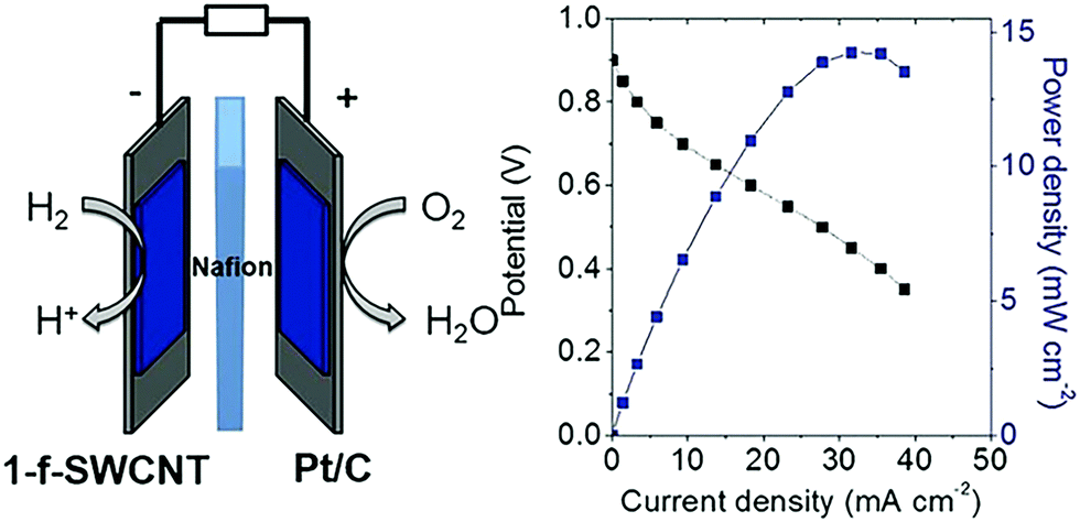
Incorporating amino acids or peptides directly into the P2N2 ring of hydrogen oxidation catalysts [Ni(PCy2NAminoAcid2)2]n+ (where Cy is cyclohexyl; amino acid is either glycine with n = 3, or arginine with n = 7), results in efficient Ni based complexes for hydrogen oxidation and production.296 An arginine-based Ni complex exhibited a turnover frequency of ∼210 s−1 at acidic pH (0), which decreased at higher pH values, reaching ∼40 s−1 at pH = 7.296 This arginine-based Ni complex was immobilized onto single-wall carbon nanotubes (SWCNTs) covalently modified with naphthoic acid groups and used as the anode (0.3 μg cm−2 loading) of an H2/O2 PEFC. Pt/C was used in the cathode (1 mg cm−2 loading) and Nafion® as the polymer electrolyte in the MEA. PEFC with the arginine-based Ni complex exhibited an OCV of ∼0.9 V and ∼14 mW cm−2 power density at ∼0.5 V (Fig. 11), in comparison to an OCV of ∼1 V and 94 mW cm−2 power density for a PEFC employing Pt/C as the anode and cathode catalyst. These initial in situ PEFC performance results demonstrated the ability of an arginine-based Ni complex to operate at highly acidic conditions, delivering only five times less current or power density at very low loading compared to Pt/C.297 These preliminary PEFC performance results are superior to the ones reported earlier utilizing arginine-based Ni bis-diphosphine complexes as the anode catalyst.127,298,299 In the case of a PEFC with cobalt (Co) supported on nitrogen doped carbon as the cathode and arginine-based Ni bis-diphosphine complexes supported on multi-wall carbon nanotubes, an ∼0.74 V OCV and 23 μW cm−2 max power density was reported, whereas an OCV of ∼0.85 V and 70 μW cm−2 max power density was demonstrated when Pt/C was used as the cathode (operation at 60 °C, ∼0.45–0.65 mg cm−2 loading at each side).300
 | ||
| Fig. 11 Polarization (black) and power density (blue) curves for an MEA employing [Ni(PCy2NArg2)2]7+ (denoted as 1-f-SWCNT) and Pt/C as the anode and cathode catalysts, respectively. Experimental conditions: anode loading: 0.3 μg cm−2, cathode loading (Pt/C): 1 mg cm−2, Nafion® as the polymer electrolyte, 60 °C cell temperature. Reprinted with permission from ref. 297. Copyright 2017 Wiley-VCH. | ||
The utilization of Ni bis-diphosphine complexes as hydrogen oxidation and evolution catalysts is not novel; it was proposed a decade earlier by incorporating these complexes into multi-wall carbon nanotubes via grafting.127 However, the preliminary MEA testing results for hydrogen production and evolution reactions were disappointing, since a two orders of magnitude smaller current density was reported for Ni bis-diphosphine complexes based MEAs compared to Pt/C MEAs. This discrepancy was attributed to the different catalyst loadings used; Ni bis-diphosphine complexes based MEAs had a ∼0.06 mg cm−2 loading compared to ∼0.5 mg cm−2 loading for Pt/C MEAs.127
Recently, a revisited design was reported, where ligands were covalently immobilized via amide coupling on the surface of MWCNTs and, then, the nickel metal centers were introduced with [Ni(CH3CN)6]2+ or [Ni(H2O)6]2+.298 The activity of these immobilized Ni bis-diphosphine complexes on MWCNTs were compared to commercial Pt/C (46% wt) MEAs with 0.05 mg cm−2 loading in a rotating disk electrode (RDE) setup using 0.5 M H2SO4 solution (Fig. 12). The total amount of Pt present in the electrode was ∼2.5 × 10⁻⁷ mol cm−2, whereas the total amount of Ni present in the electrode was 10-fold lower (∼2.5 × 10⁻⁸ mol cm−2). At room temperature (∼25 °C), the activity of the bio-inspired electrocatalyst was approximately one order of magnitude less than the activity of commercial Pt/C; at 85 °C operation, though, the bio-inspired catalyst was only ∼30% less active than Pt/C for hydrogen oxidation, while it outperformed the commercial catalyst by ∼20% for hydrogen production.298
 | ||
| Fig. 12 Catalytic activity for hydrogen evolution (left of E = 0 V) and oxidation (right of E = 0 V) obtained from linear sweep voltammetry experiments in 0.5 M H2SO4 solution recorded at 2 mV s−1 of the Ni–bis-diphosphine functionalized MWCNT (black color) and commercial Pt/C electrodes (red color). Measurements at 25 °C and 85 °C are represented by a dashed and a solid trace, respectively. Reproduced from ref. 298 with permission from the Royal Society of Chemistry. | ||
A chemically inert polymer P(GMA-BA-PEGMA) (poly(glycidyl methacrylate-co-butyl acrylate)-co-poly(ethylene glycol)methacrylate) was used to immobilize Dubois' Ni bis-diphosphine complex with cyanide and glycine [Ni(PCy2NGly2)2]2+ on the surface of the electrode and prevent the electrical contact between the metal complexes within the polymer and the electrode.280 The thick polymer film creates two distinct regions, where different reactions occur. In the region close to the surface of the electrode, hydrogen is oxidized via the Ni-complex, while, in the outer region, which is electrically disconnected from the electrode, preventing re-oxidation of the catalyst, a protonated Ni0 complex reduces oxygen to water by using the electrons produced from the hydrogen oxidation reaction in the inner layer (Fig. 13).
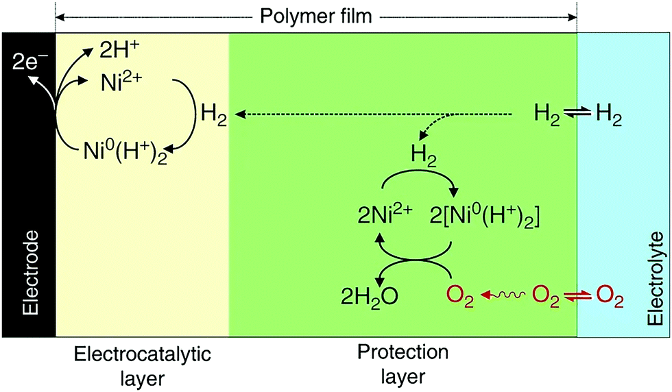 | ||
| Fig. 13 A chemically inert polymer (P(GMA-BA-PEGMA)) is used to immobilize Dubois’ Ni bis-diphosphine with glycine complex [Ni(PCy2NGly2)2]2+ on the surface of the electrode and prevent electrical contact between the metal complexes located within the polymer and the electrode. Two distinct regions are created: in the inner region (electrocatalytic layer), the Ni complex oxidizes H2, while in the outer region (protection layer), Ni0 reduces O2 to H2O using the electrons produced from H2 oxidation in the inner region. Reprinted with permission from ref. 280. (Creative Commons Attribution 4 International License). | ||
The thickness of the polymer film is crucial for the effective protection of the metal center from oxygen. Even though thinner films produced high current densities for the oxidation of hydrogen, they degraded immediately upon the addition of oxygen in the gas feed (Fig. 14a). For thicker polymer films, the current density for hydrogen oxidation was not affected by the presence of oxygen in the gas feed for the first 7 h; after 24 h of continuous exposure to oxygen, though, the current density decreased to ∼75% of its initial value, due to the oxidation of the Ni bis-diphosphine complex and oxidation of phosphines (Fig. 14b).280,301
 | ||
| Fig. 14 Hydrogen oxidation by the Ni bis-diphosphine complex with glycine/polymer P(GMA-BA-PEGMA) film of different thicknesses in the presence of oxygen. (a) Chronoamperometric measurements under 90% H2/10% N2 with addition of 5% O2 (90% H2/5% N2) over 10 min; (b) chronoamperometric measurements under 90% H2/5% N2/5% O2 gas mixture over 24 h. Experimental conditions: ∼0.54 V vs. SHE, pH = 3, 0.1 M MES/0.1 M HEPES + HClO4, 25 °C, 500 and 2000 rpm rotation speed for (a) and (b), respectively. Reprinted with permission from ref. 280. (Creative Commons Attribution 4 International License). | ||
3.4 Nature-inspired electrocatalysts for the carbon dioxide reduction reaction
Electrochemical reduction of carbon dioxide (CO2) has attracted great research interest, as it could contribute to the reduction of the greenhouse effect and generate useful chemicals. It involves multi-proton and multi-electron routes to convert CO2 to an activated form of carbon (with the exception of carbon monoxide), which have sluggish kinetics and require high reducing potentials.302,303 Theoretically, the formation of different carbon products depends on the applied potential,304 even though directing the reduction of CO2 toward a specific reaction pathway is difficult to achieve.305 The initial transfer of a single electron to CO2 to create CO2,ads is considered the rate determining step, due to the high energy input required to enable this step.305 The reactivity of CO2,ads on the surface of metal catalyst dictates the reaction pathway that will be chosen, leading to different end products. For example, in the presence of gold or silver catalyst, CO2,ads is converted to CO, whereas copper catalyzes the reaction of CO2 to formic acid (HCOOH), methane (CH4), and ethylene (C2H4) (Fig. 15).305 Several electrocatalysts for the reduction of CO2 have been developed,306 including metal nanoparticles and oxides, chalcogenides and carbon based materials, and their activity was optimized via modification of their defect density on their surface,302,307–309 particle size,310 morphology,311,312 and electrode thickness.313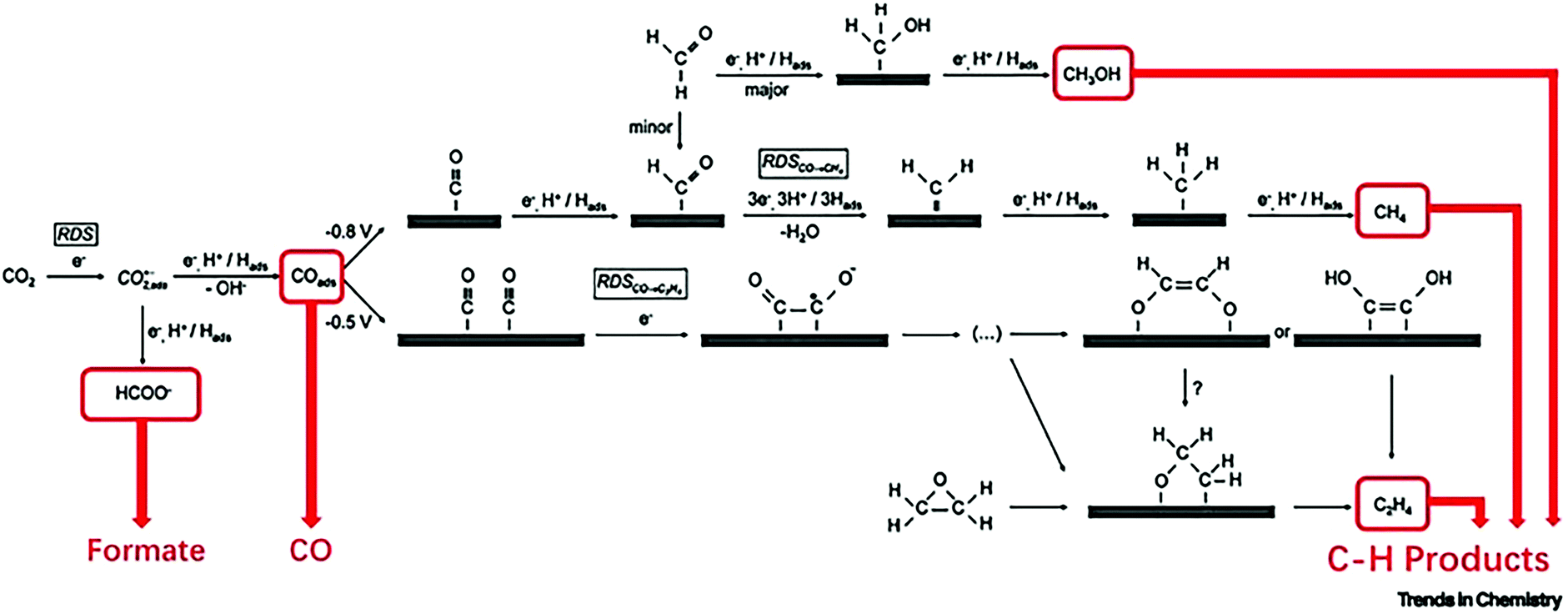 | ||
| Fig. 15 Mechanism of the electrochemical reduction of carbon dioxide on copper. Reaction pathways leading to the formation of formate, CO, and C–H products are highlighted. Abbreviation: RDS, rate-determining step. Reprinted with permission from ref. 314. Copyright 2019 Elsevier. | ||
Another important issue contributing to the sluggish kinetics of CO2 reduction is the insufficient concentration of CO2 on the surface of the catalyst layer. The concentration of carbon dioxide near the cathode increases with increasing metal cation size,315 but this effect is restricted by the solubility of relevant salts. The application of large potentials can also improve the adsorption of CO2 at the expense of increased hydrogen evolution.316 On the contrary, nanostructured metal electrodes (Au, Pd nanoneedles) produce a high local electric field at low overpotentials, which concentrates electrolyte cations and enhances the concentration of CO2 near the cathode catalyst layer.317 High current densities of ∼22 mA cm−2 at −0.35 V vs. Ag/AgCl (gold nanoneedles) and ∼10 mA cm−2 at −0.2 V vs. Ag/AgCl (palladium nanoneedles) for CO and formate production were reported, respectively.317
Hence, bio-inspired approaches have been employed to improve the activity of electrocatalysts toward reduction of CO2, via inspiration from biological processes or the structure of enzymes, which catalyze the same reactions. These will now be reviewed.
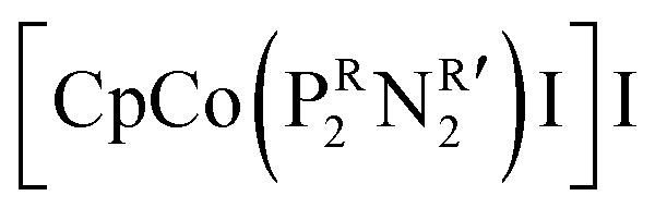
An oxygen tolerant cathode was recently synthesized, inspired by the process leading to an increase in CO2 concentration during photosynthesis (Fig. 16a).322 This bio-inspired cathode consists of a carbon fiber gas diffusion electrode with a catalyst layer and a polymer with intrinsic microporosity (PIM)323 coated on its opposite sides.322 PIM imitates the role of enzymes; it filters oxygen and is highly permeable to CO2. Its size-selective pores reject oxygen molecules (∼0.35 nm kinetic diameter)324,325 and facilitate the transport of slightly smaller CO2 molecules (∼0.33 nm kinetic diameter)324,326 effectively decreasing the O2 to CO2 ratio of the feed stream reaching the catalyst layer, and, hence, favoring the reduction of CO2 to CO (Fig. 16b).322 The incorporation of this bio-inspired electrode into the electrolyzer resulted in a ∼76% faradaic efficiency to CO and ∼27 mA cm−2 current density at −1.1 V vs. RHE (feed gas stream with 5% O2). As the oxygen concentration in the gas stream increased, the faradaic efficiency of CO decreased, reaching ∼20% and ∼35 mA cm−2 current density at 35% O2 in the gas stream, indicating that oxygen reduction dominated the electrode reaction at high O2 concentrations in the gas stream (Fig. 16c).322 During continuous operation over 18 h, stable operation was observed for gas streams containing 5% and 20% O2 (Fig. 16d).322
 | ||
| Fig. 16 (a) Illustration of plant photosynthesis in the presence of O2; (b) schematic diagram and cross-section SEM image of the architecture of the PIM–CoPc/CNT hybrid electrode. Atoms: black, carbon; red, oxygen; pink, cobalt; blue, nitrogen; (c) faradaic efficiency of CO (FECO), and total current density (jtotal) vs. volume fraction of O2 in the CO2 feed gas; (d) FECO and jtotal during an 18 h electrolysis at O2 volume fractions of 5% (solid marker) and 20% (hollow marker). PIM–CoPc/CNT is used as the cathode, CoOx/CNT as the anode catalyst, and 0.5 mol L−1 aqueous KHCO3 as the electrolyte. Cell voltage: 3.1 V. Reprinted with permission from ref. 322. Copyright 2019 Elsevier. | ||
Another electrode design employed to increase the concentration of CO2 at the surface of the catalyst layer was inspired from the structure of alveoli in a mammalian lung.327 Alveoli consist of thin epithelial cellular membranes with low water permeability and high gas diffusivity.107,108,328 During pulmonary circulation, inlet air rapidly penetrates through bronchii to alveoli and reaches the blood cells, where haemoglobin protein binds oxygen and releases CO2.327 The structure of the alveoli-inspired electrode (∼20–80 nm thickness) comprises a layer of gold nanoparticles (∼0.15 mg cm−2 loading) acting as the catalyst sputtered on a polyethylene membrane, whose hydrophobicity and network of interconnected fibers (∼40–500 nm pore size) allow unobstructed diffusion of CO2 toward the catalyst layer. To fully replicate the structure of a closed alveolus with macroscopic tubes (bronchioli) for gas transport to and from the lung, the flat Au coated polyethylene membrane was rolled and sealed to form a bi-layer pouch-type structure. Electrochemical reduction of CO2 was conducted in an H-type cell using a Selemion™ anion exchange membrane as separator and CO2 saturated potassium bicarbonate (0.5 M KHCO3) as the electrolyte. A faradaic efficiency of ∼92% for CO production and high current density of ∼25 mA cm−2 at −0.6 V vs. RHE were achieved.327
An additional nature-inspired strategy for the design of electrocatalysts for the reduction of CO2 is derived from the structure of dehydrogenases. CO– (CODH) and formate-dehydrogenases (FDH) catalyze the reversible CO2 reduction via their single- or multi-metallic active sites composed of earth abundant metals, such as nickel–iron or molybdenum–sulfur–copper complexes in CODHs or single metals tungsten or molybdenum in FDHs.329–332 In addition to their active metal centers, proton relays on their outer coordination sphere play an important role in the catalytic activity of these enzymes.329–332
NiFe CODHs utilizing [NiFe4S4] as the active site are highly active toward CO2 to CO conversion with ∼12 s−1 turnover frequency at low overpotentials (less than 100 mV).333–336 Ni acts as a Lewis base transporting an electron to the unoccupied molecular orbital of CO2, increasing the negative partial charges of oxygen atoms bound on the Fe center acting as a Lewis acid.333–336
Moreover, a CODH-inspired catalyst containing cofacial Fe tetraphenylporphyrin dimer (o-Fe2DTPP) demonstrated a high faradaic efficiency (∼95%) and turnover frequency (∼4300 s−1) at high overpotential (∼0.7 V) for the conversion of CO2 to CO in a DMF–water solution (10 wt%).337 The introduction of electronically different substituents to porphyrin positions can alter the overpotential and turnover frequency. Attachment of electron withdrawing groups, such as perfluorophenyl substituents to the meso-positions of the porphyrin rings of CODH-inspired catalyst decreased the overpotential to ∼0.3 V; however, the withdrawal of electrons also reduced the electron density of the active metal center, resulting in a decrease in turnover frequency.337 On the contrary, incorporation of electron donating groups, such as mesityl on the porphyrin groups resulted in high turnover frequencies but high overpotentials.337
 was synthesized based on the structural characteristics of CODH/FDH.338 It contained
  diphosphine (1,5-diaza-3,7-diphosphacyclooctane) ligands, with two pendant amine molecules acting as proton relays during the reduction of CO2. Four different diphosphine ligands with phenyl or cyclohexyl substituents on phosphorus (PCy or PPh) and benzyl or phenyl substituents on nitrogen (NBn or NPh) were prepared and were active toward the electrochemical reduction of CO2 to formic acid, exhibiting 90 ± 10% faradaic efficiencies.338 The cobalt catalyst with (PCy2NBn2) ligand demonstrated the highest activity with a turnover frequency (TOF) value higher than 1000 s−1. However, these enzyme-inspired molecular catalysts were not stable, as a complete loss of their activity was observed after 1 h of electrolysis.338
Furthermore, a distinct structural characteristic of iron hydrogenases was used as the source of inspiration for the design of molecular catalysts for the hydrogenation of CO2 to formamide and formate. The ortho-hydroxypyridine present in iron-based hydrogenases is crucial toward hydrogen splitting as it promotes bond scission.339 Hence, the hydrogenase-inspired catalyst consisted of a manganese complex with a nitrogen ligand containing ortho-hydroxypyridin, namely 6,6′-dihydroxy-2,2′-bipyridine.340 Manganese was chosen as the metal center due to the presence of Mn hydride intermediates derived from the interaction between Mn and hydroxy-functionalized ligand, leading to increased activity toward CO2 reduction to HCOOH.341,342 Turnover numbers of ∼6250 (in the presence of DBU (1,8-diazabicyclo[5.4]undec-7-ene)) and ∼588 (in the presence of secondary amine diethylamine) were achieved for the hydrogenation of CO2 to formate and formamide, respectively.340
These initial results show the potential of these enzyme-inspired electrodes as CO2 reduction catalysts, even though further research is needed to optimize their structure and improve their durability. Thorough reviews about molecular catalysts for reduction of CO2 are available elsewhere.343–345
4. Connecting nano- to macro-scale: hierarchical transport networks in electrocatalysis
In an electrochemical reaction involving a porous electrocatalyst, reactants must move from the gas or fluid stream into the electrocatalyst layer and reach the active sites on its surface. A high specific, internal surface area is desirable to achieve a high concentration of active sites per unit catalyst mass, suggesting the employment of nanoporous electrocatalysts. However, the diffusion of reactants through electrocatalytic layers is greatly influenced by the geometry and organization of their pores. In non-hierarchical structures, there is high mass transfer resistance within the nanopores, resulting in decreased overall rates.101,111 Hence, it is crucial to minimize the effects of transport limitations to increase yield; this is not a trivial problem, due to the various phases required for transport of molecular reactants and products, ions and electrons.A nature-inspired approach to reduce diffusion limitations is the utilization of hierarchically structured porous materials with an optimized network of narrow and broad pores. Nature can provide the mechanistic basis to discover the optimal network structure of the pores, as hierarchical transport networks are widely employed in various natural systems in plants and animals, such as their circulatory and respiratory systems (Fig. 17). In such systems, convective flow dominates transport at large length scales, while diffusion takes over at small length scales. This transition corresponds to a Péclet number of unity and is accompanied by a quite sudden change in the channel architecture: the fractal distribution of channel diameters at large scales (pressure driven) transitions into a uniform distribution of narrow channels (concentration or chemical potential driven). This optimal structural characteristic is universal and witnessed in lungs, plants, and other biological transport networks.107–110,346–349
 | ||
| Fig. 17 Systematic methodology for the nature-inspired design of hierarchically structured electrocatalysts. Image of the porous catalyst layer structure (“Nature-inspired concept” section) was reproduced from ref. 350 with permission from the Royal Society of Chemistry. | ||
A numerical model was developed to demonstrate the significance of the microstructure of the cathode catalyst layer (CCL) in the performance of a PEFC (Fig. 18), because transport limitations in the CCL are responsible for a sharp drop in efficiency when operating at high current density.351 This CCL was assumed to consist of several spherical Pt/C agglomerates, each surrounded by Nafion ionomer. The composition and size of these agglomerates (∼50–5000 nm) depend on the formulation of the catalyst ink, which is sprayed onto the polymer membrane to form the MEA.
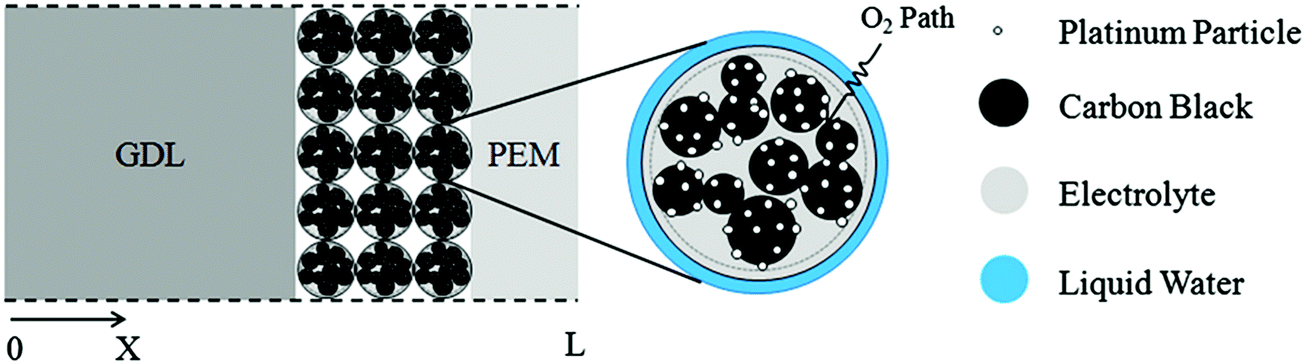 | ||
| Fig. 18 Modeling domain of the PEFC, including the cathode gas diffusion layer (GDL), cathode catalyst layer, and polymer electrolyte membrane (PEM). The catalyst layer is composed of spherical agglomerates, each surrounded by a liquid water film. The coordinate x = L corresponds to the interface between the membrane and the anode catalyst layer; x = 0 corresponds to the interface between the cathode flow plate with gas channels and the cathode GDL.351 Reprinted with permission from ref. 351. Copyright 2013 Elsevier. | ||
This optimized CCL design leads to high Pt utilization, even at very low Pt loadings (∼0.01 mg cm−2), as sufficient oxygen concentration is present along the entire radius of the agglomerate (Fig. 19a). On the contrary, in a conventional design, Pt resides at the center of the agglomerate and is exposed to very low oxygen concentrations, underutilizing the catalyst (Fig. 19b). When this optimized CCL design is incorporated into a lung-inspired PEFC (described in detail in Section 5.3), the DoE target for platinum utilization of ∼8 kW gPt−1 is surpassed352 at N = 4 generations of the fractal flow field and reaches a maximum of ∼36 kW gPt−1 at N = 6 generations (Fig. 19c).
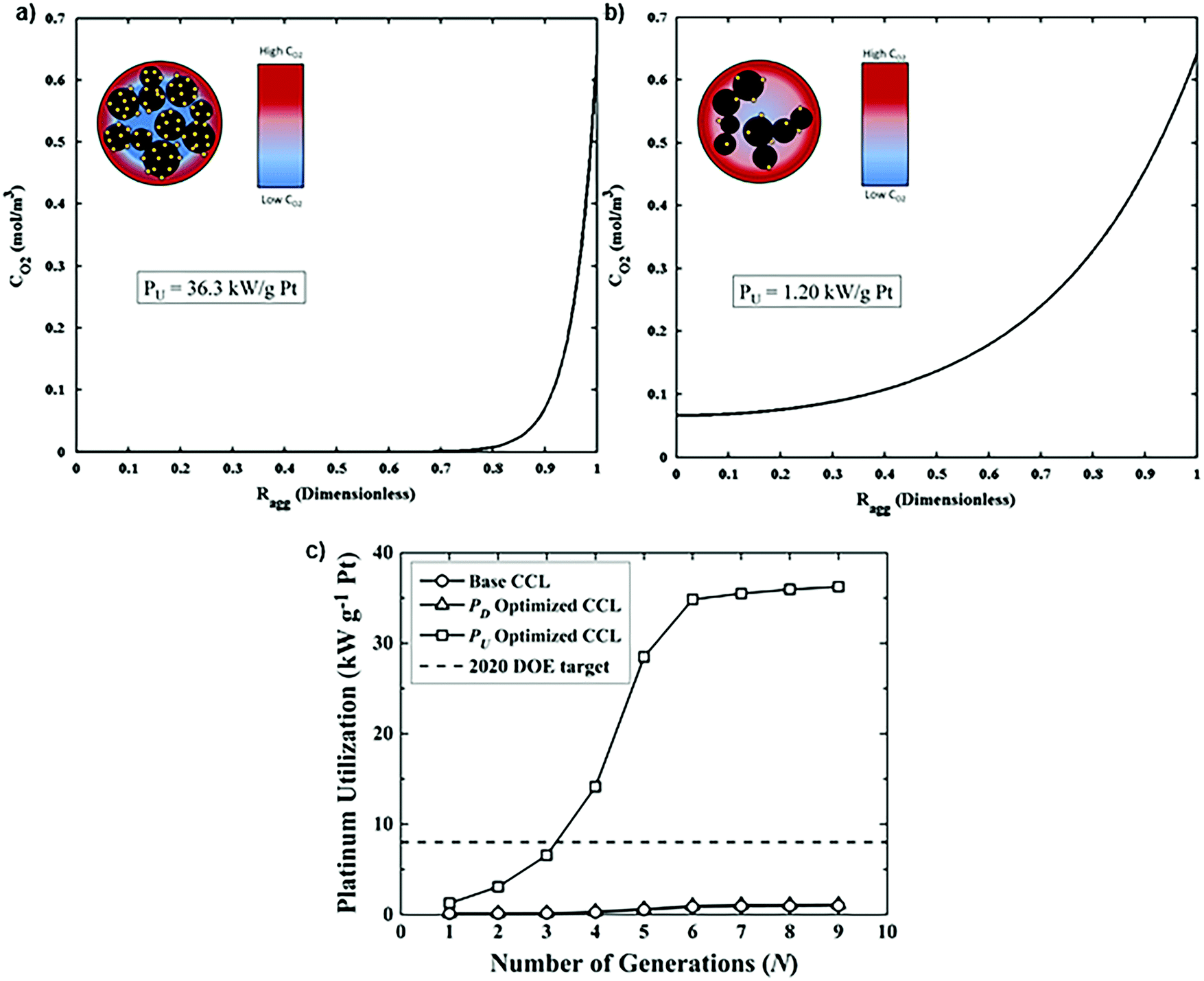 | ||
| Fig. 19 (a) Dissolved oxygen concentration in a single agglomerate in a catalyst layer with mPt = 0.40 mg cm−2, as a function of the dimensionless radial coordinate in an aggregate, ragg. Cell operating at 0.40 V. (b) Dissolved oxygen concentration in a single agglomerate in a catalyst layer with an ultra-low platinum loading, mPt = 0.010 mg cm−2. Cell operating at 0.40 V. (c) Effect of the number of fractal branching generations on platinum utilization (PU) for the base and optimized CCL microstructures. The operating conditions are anode and cathode stoichiometry ratios of 1.5 and 2 respectively, ragg = 100 nm, and 100% RH. Fig. 20(a and b) were reprinted with permission from ref. 351. Copyright 2013 Elsevier. | ||
Hence, these modeling results demonstrate the significance of a rational design based on hierarchically structured electrocatalysts, which can significantly reduce the cost of the MEA. However, the mitigation of degradation of Pt must be considered into the design, as, at such low catalyst loadings, the electrochemically active surface area can rapidly decrease leading to significant PEFC losses.
In summary, it is evident that there is a need for a new methodology for the design of highly active and cost-efficient electrocatalysts for key, energy conversion related, electrochemical reactions, which can be successfully fulfilled by the implementation of a nature-inspired approach, using the NICE methodology. Even though challenges regarding long-term stability, cost, scale-up, and fundamental understanding of kinetic and reaction barriers in key elementary steps of electrochemical reactions still need to be addressed, the nature-inspired approach is a powerful avenue towards the rapid growth of effective electrocatalyst designs.
5. Bio-inspired electrochemical devices
In the following section, we provide examples of the nature-inspired approach for the design of nature-inspired electrochemical devices (Fig. 20). In the case of bio-fuel cells, the term “bio-inspired” is limited to the different living enzymes or microbes employed as electrodes, and is, in fact, bio-integration, as biological components are explicitly used. In contrast, in the case of other types of fuel cells and batteries, the nature-inspired approach does not require biological components; in addition, the approach aims to redesign electrochemical devices across different scales, encompassing not only the electrodes but the entire structure of the battery or the flow fields of, e.g., polymer electrolyte fuel cells (PEFCs).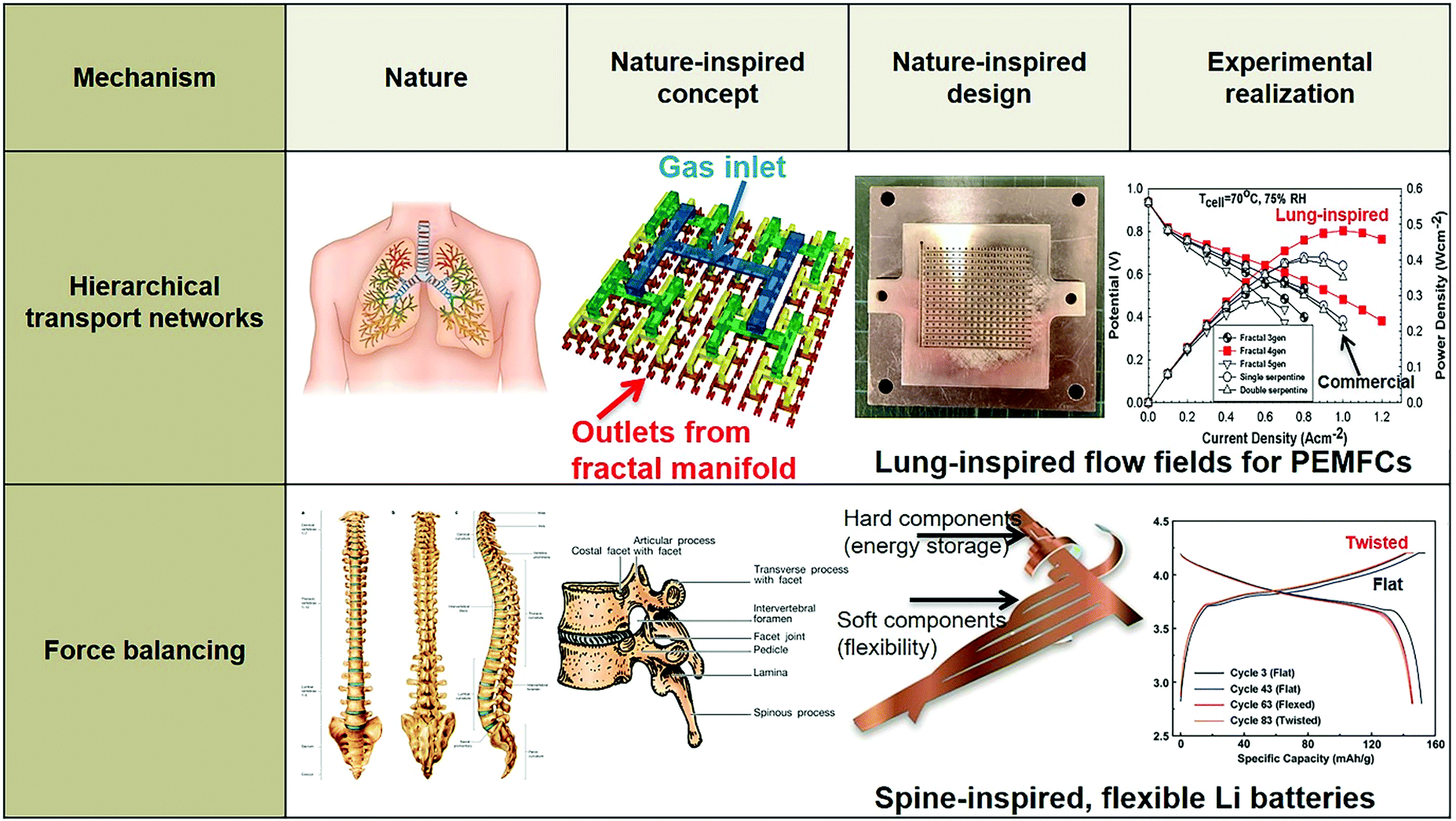 | ||
| Fig. 20 Example of bio-inspired designs for lung-inspired flow fields for PEFCs (top) and flexible Li–S batteries (bottom). Images of the spine (under “Nature” and “Nature-inspired concept”) were reprinted with permission from ref. 353. Copyright 2018 Elsevier. Images of the bio-inspired battery design (under “Nature-inspired design”) and battery performance (under “Experimental realization”) were reprinted with permission from ref. 393. Copyright 2018 Wiley-CVH. | ||
5.1 Biofuel cells
Biofuel cells (BFCs) are fuel cells using a biogenous fuel or catalyst, or their combination, to convert chemical energy stored in biodegradable substances directly into electricity.354,355 Biofuel cells are categorized into enzymatic (EFCs) and microbial fuel cells (MFCs), depending on the nature of the biocatalyst employed, and offer a clean energy alternative to fossil fuels due to the utilization of cost efficient, environmentally friendly, and renewable fuels (such as sugars and components in wastewater) to produce electrical energy. However, the main obstacle toward the commercialization of this technology is its short lifetime and low power density,355 limiting the range of applications to powering microelectronic systems, such as sensors and actuators,356–358 and for environmental remediation.359,360The different biocatalysts incorporated in these two types of biofuel cells leads to large differences between them in volumetric size, power output and targeted applications.355,361 EFCs and MFCs use redox enzymes and living microorganisms (e.g. bacteria, yeast cells), respectively, as biocatalysts for power generation. As a result, EFCs can produce high power density and are well-suited to miniaturization, sensors, and wearable or implantable devices fueled by endogenous substances (such as glucose in the blood stream).362–366 On the contrary, MFCs are mainly used as bioreactors for purification of wastewater or as long-term power generators for small devices in remote locations. Despite the promising potential of biofuel cells, the commercialization of these systems is limited by their low power density and stability.355
To circumvent these issues, research has been focused on the development of nanostructured materials as electrodes with tailored pore size (∼40–300 nm), high surface area and porosity to significantly improve the electron transfer between the biocatalyst and the electrode, and the diffusion of mediators to the electrode. The most common materials used as electrodes in BFCs are carbon- and polymer-based. Carbonaceous materials (carbon nanotubes, graphene, carbon nanoparticles)355,367–377 possess excellent mechanical and chemical stability, good conductivity and biocompatibility, with the ability to extract the electrons from the biocatalysts without being deactivated. Conducting polymers (polyaniline (PANI), polypyrrole (PPy), poly(ethylenimine) (PEI)) have high stability, conductivity, and surface area transforming them into attractive candidates as electrodes for BFCs.355,378–381
An example of carbon modified electrodes is magnesium oxide-templated mesoporous carbon (MgOC) with high surface area (∼580 m2 g−1) for efficient biocatalytic reactions in its mesopores and facile mass transport though its macropores.382 The electrode was coated with a biocatalytic hydrogel composed of a conductive redox polymer d-FAD-GDH (deglycosylated flavin adenine dinucleotide-dependent glucose dehydrogenase), and a cross-linker. This MgOC modified electrode produced ∼30-fold higher current density (∼3 mA cm−2) than a flat carbon electrode with the same hydrogel loading (∼1 mg cm−2), while, after 220 days of testing, a ∼5% loss of the initial catalytic current was observed, indicating that immobilization of the enzyme in the mesopores of carbon support can significantly improve the enzyme's stability.382
As these biofuel cells are bio-integrated, rather than bio-inspired fuel cells, a thorough review of the electrodes employed in biofuel cells is beyond the scope of this manuscript; readers are referred to other reports in the literature.355–358,383–385
5.2 Bio-inspired batteries
Among the first bio-inspired approaches for the development of electrodes for Li-ion batteries was the utilization of viruses, such as M13.386,387 A self-assembled layer of virus (M13)-templated cobalt oxide nanowires serving as the active anode material was formed on top of polyelectrolyte multilayers acting as the battery electrolyte, and this assembly was stamped onto platinum microband current collectors.386,387 The microbattery electrodes exhibited a similar charging/discharging curve as that of commercial cobalt oxide nanoparticles, even at a high charging rate of ∼255 nA, demonstrating the potential of this approach toward the design of new electrode materials.386,387Nowadays, the facile development of flexible and wearable electronics creates the need for batteries with high flexibility and energy density. In conventional battery designs these two characteristics are at odds with each other;388,389 ultrathin batteries may be flexible, but have low energy density and vice versa, requiring the connection of numerous battery units in series to increase their energy density.390–392
A nature-inspired approach to solve this issue is the design and manufacturing of a Li-ion battery based on the structure of the spine. The spine or vertebral column consists of 33 bones (vertebrae), which interlock with each other, providing the main support of the human body and its flexibility. To prevent friction between vertebrae, each vertebra is separated from the others by intervertebral discs.
Based on this structural characteristic of the human spine, flexible Li-ion batteries with high energy density were manufactured (Fig. 21a).393 Each of the conventional anode/separator/cathode/separator battery stack components were placed in different strips with multiple branches; then, each strip was wrapped around the backbone to form thick stacks of electrodes, corresponding to the vertebral column. The unwound part interconnecting these thick stacks of electrodes functions as the marrow, providing high flexibility to the battery (Fig. 21b). The spine-inspired design of the Li-ion battery demonstrated an ∼242 W h L−1 power density and ∼94% retention. At 0.5C, the discharge capacity was above 125 mA h g−1 under continuous dynamic load. Mechanical load tests revealed the flexibility of this design, since the largest strain on the interconnected joints was ∼0.08% compared to ∼1.8% and ∼1.1% for a prismatic and stacked pouch cell, respectively.393
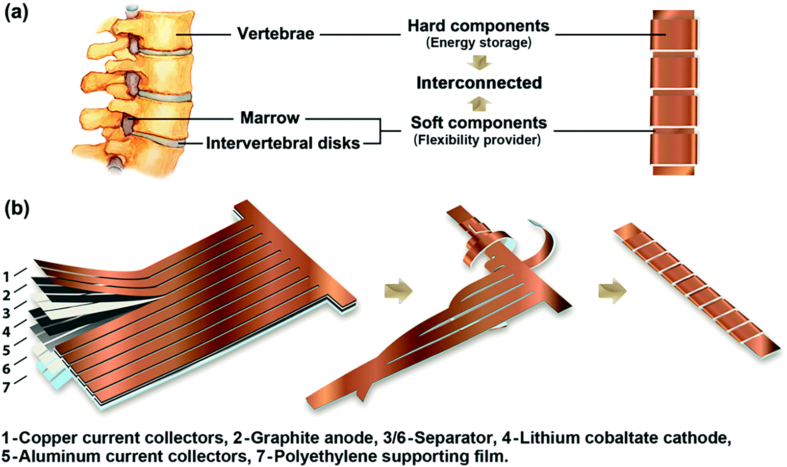 | ||
| Fig. 21 (a) Schematic illustration of the bio-inspired design for the Li-ion battery, where the vertebrae correspond to thick stacks of electrodes and soft marrow corresponds to thin, flexible polyethylene foil interconnecting these stacks of electrodes. (b) The fabrication process of spine-inspired battery, where multilayers of electrodes were first cut into the desired shape, then strips extending out were wound around the backbone to form a spine-inspired structure. Reprinted with permission from ref. 393. Copyright 2018 Wiley-CVH. | ||
Another source of natural inspiration is cartilage. Cartilage is a tough, flexible connective tissue, serving as the center of ossification for bone growth and covering the surface of the joints, reducing the friction between adjacent bones and preventing damage (Fig. 22).394,395
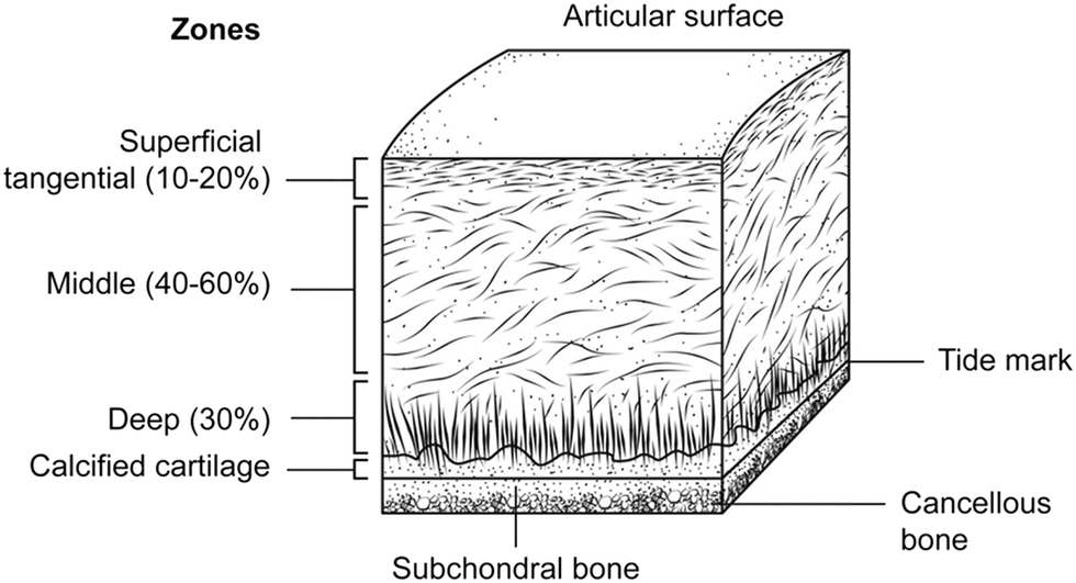 | ||
| Fig. 22 Layers of articular cartilage. Note the horizontal orientation of cells in the superficial layer, contrasted with the vertical orientation in the deep layer. Reprinted with permission from ref. 394. Copyright 2015 Elsevier. | ||
It comprises collagen fibers and a dense extracellular matrix (ECM) with a sparse distribution of cells called chondrocytes.394 The ECM is composed of water, collagen, proteoglycans and non-collagen proteins, and retains the water within the cartilage, which is critical for its unique mechanical properties. Cartilage consists of several zones, namely, the superficial, middle, deep, and the calcified zone, distinguished by the distribution of the collagen and the orientation and shape of the chondrocytes.394
The superficial zone contributes 10–20% to the cartilage thickness and protects the cartilage from shear, tensile, and compressive forces imposed by articulation. This zone is responsible for most of the tensile properties of cartilage and consists of collagen fibers tightly packed and aligned parallel to the articular surface. Below the superficial zone lies the middle zone, which contains thicker collagens than the superficial zone to resist compressive forces.394 Right below the middle zone lies the deep zone, which constitutes the second layer of resistance to compressive forces. It contains thicker collagen fibers than in the previous layers perpendicular to the articular surface and chondrocytes oriented vertically to the underlying bone. Finally, the calcified zone secures the cartilage to the bone by attaching the collagen fibrils of the deep zone to subchondral bone.394
To imitate the nanofiber networks of cartilage, aramid nanofibers were synthesized from Kevlar via layer-by-layer deposition and used as ion conducting membranes for Li-ion batteries,396 solid electrolytes for Zn batteries,397 and separators for redox flow batteries.398
Ion conducting membranes are a key component of Li-ion batteries, providing high ionic mobility to Li+ ions, stiffness and flexibility. The safety issues of Li-ion batteries are related to dendrite growth and anode expansion in the charged state;399–401 the membranes are pierced during dendrite growth, which could lead to battery failure, short-circuiting and fire.402 Aramid nanofibers (∼1 mm length, ∼5–10 nm average diameter) were used as ion conducting membranes, due to their low Ohmic resistance, high mechanical flexibility, ionic conductivity and resistance to dendrite growth.396
Investigation of dendrite growth was carried out under high current density (∼10 mA cm−2); a copper (Cu) electrode was used to examine the expansion of Cu dendrites (growth zones of ∼50–100 nm and ∼25 nm tip diameter),396 due to their smaller size than Li dendrites, making the suppression of Cu dendrites more challenging than those of Li. The theory of electrochemical dendrite growth403 indicates that if the local mechanical properties of the ion conducting membrane are sufficient to prevent mechanical stress from Cu dendrites, it will also suppress Li dendrites, which are much softer.
Copper electrodes were examined via scanning electron microscopy (SEM) after a total charge of 0.006 mA h cm−2, and dendrites with ∼500 nm size were formed on bare copper electrode. The size of the copper dendrites was significantly reduced to ∼100–200 nm after depositing a coating of aramid nanofibers on the electrode with a film thickness of ∼162 nm. As the thickness of the coating was increased, the suppression of copper dendrite growth was enhanced as well, and no dendrite formation was observed for coatings with thickness of ∼809 nm.396
Dendrite growth also has a detrimental effect on the energy density and cyclability of zinc (Zn) batteries, as Zn dendrites can easily traverse the inter-electrode space, piercing existing separators. Solid electrolytes can provide a solution to this issue at the expense of low mobility of divalent ions, leading to low energy density.397
A cartilage-inspired composite of aramid nanofibers, poly-ethylene oxide (PEO) and zinc trifluoromethanesulfonate (Zn(CF3SO3)2) can serve as a solid electrolyte providing facile ion transport and excellent mechanical properties.397 PEO and Zn(CF3SO3)2 act as the ion transport components of the solid electrolyte; the composition of PEO/Zn(CF3SO3)2/aramid nanofibers was optimized with respect to Zn2+ conductivity and mechanical properties with an optimal ratio of 9:3:1. These composites were thinner (∼10 μm) than a commercial separator for Zn or Li batteries (∼30–200 μm), the interfilament distances in the aramid nanofibers network were ∼10–20 and ∼2–4 times smaller than the average diameter of the stems (∼1–2 μm) and growth points of Zn dendrites (∼200 nm). Their Zn2+ conductivity was ∼2.5 × 10⁻⁵ S cm−1, 10-fold greater than the original Li batteries (∼2.5 × 10⁻⁶ S cm−1).397
This bio-inspired composite enabled Zn batteries to be rechargeable and reformable, due to the plasticity of Zn anodes and the reconfigurability of a cartilage-inspired fiber network. After 50 cycles at 0.2C, the battery retained ∼96% of its highest achievable capacity (∼123 mA h g−1) and still exceeded 90% after 100 cycles at 0.2C (Fig. 23a).397 The plasticity characteristic of this bio-inspired composite increased battery safety, since it was less prone to mechanical damage and could withstand elastic deformation from bending and plastic deformation. It also enabled shape modification to improve the ability of the battery to carry a load; various shapes of these bio-inspired batteries were tested as load bearing and charge storage elements in small drones (Fig. 23b and c), demonstrating their promising potential in the transportation industry.397
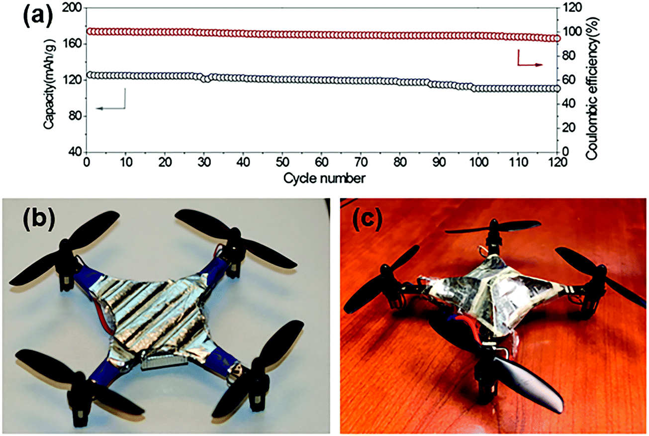 | ||
| Fig. 23 (a) Cycling performance of the Zn/PZB-931/γ-MnO2 battery at 0.2C; (b) and (c) two different designs of Zn/γ-MnO2 battery pack as a replacement for the original device cover to supplement the main power source of unmanned aerial vehicles (UAVs). Reprinted with permission from ref. 397. Copyright 2019 American Chemical Society. | ||
The feasibility of using aramid nanofiber-based films as electrically conducting separators for non-aqueous redox flow batteries has also been explored.
An ∼8.5 μm film was obtained via layer-by-layer assembly of 20 layers of aramid nanofibers of ∼425 nm thickness each. The dense network of nanofibers comprising this multilayer structure reduced the pore size of the film, while the pore network for ionic transport remained intact (Fig. 24a and b).398 The average pore size was approximately 5 nm, much less than the pore size of a commercial separator, such as Celgard 2325 (∼25 μm thick), with ∼390 nm pores on its surface (Fig. 24c and d). The small pores of aramid nanofiber-based film impeded the mobility of vanadium ions, resulting in lower ionic conductivity (∼0.1 mS cm−1) and permeability (∼0.8 × 10⁻⁷ cm2 s−1) than Celgard 2325 (∼0.6 mS cm−1 and ∼7 × 10⁻⁷ cm2 s−1, respectively).398 To further decrease the permeability of an aramid nanofiber-based separator without sacrificing its conductivity, its surface was functionalized with PDDA (poly(diallyldimethylammonium chloride)) and PSS (poly(styrene sulfonate)) polyelectrolytes. The addition of these charged PDDA/PSS layers on the surface of aramid nanofiber-based separator enabled the Donnan exclusion of the positively charged vanadium ions,404 further reducing the permeability of the functionalized aramid nanofiber-based separator to ∼0.003 × 10⁻⁷ cm2 s−1, while its conductivity remained constant.398
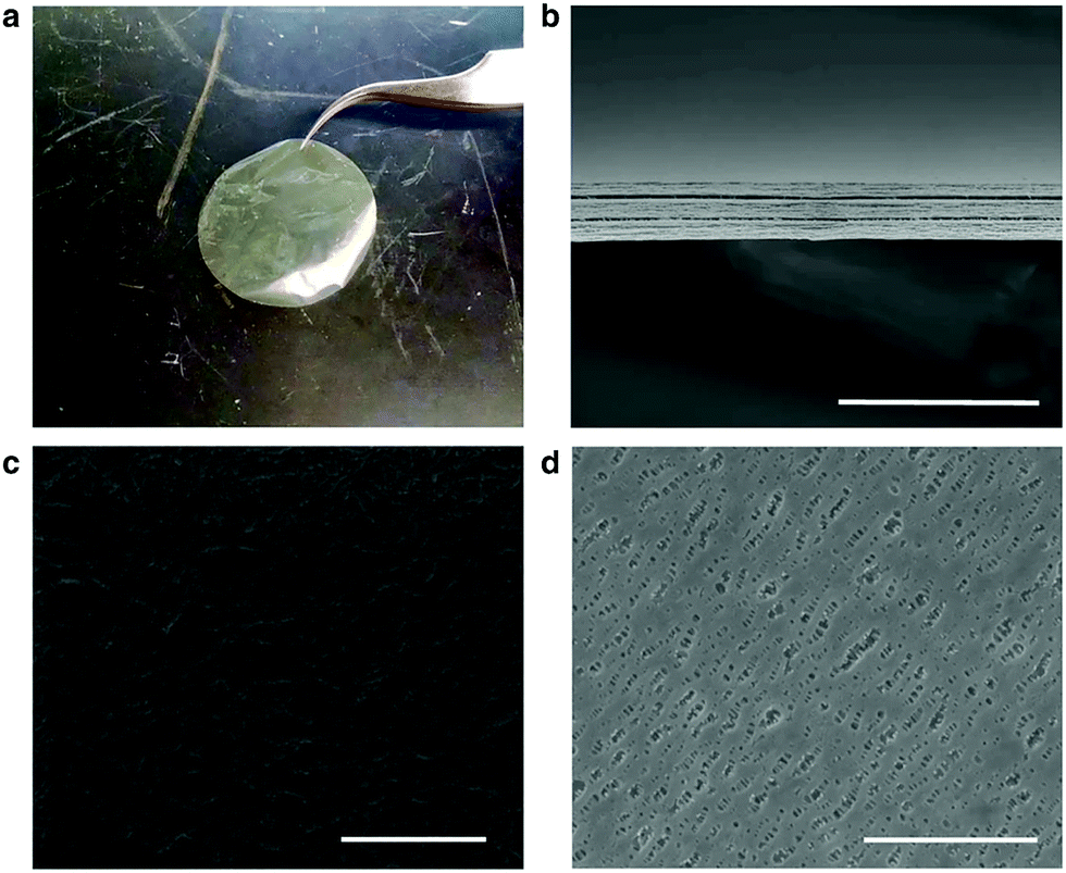 | ||
| Fig. 24 Images of the ANF and Celgard separators. (a) Optical image of a neat aramid nanofiber (ANF) separator; (b) cross-sectional SEM image of a neat ANF separator; (c) SEM image of the surface of a neat ANF separator; (d) SEM image of the surface of Celgard 2325. Scale bars represent 30 μm in (b), 500 nm in (c) and 3 μm in (d). Reprinted with permission from ref. 398. (Creative Commons Attribution 4 International License.) | ||
The low permeability of these functionalized separators translated into high coulombic efficiency (∼95% compared to ∼55% of commercial Celgard) during commercial cycling (5 h duration) and high stability, exhibiting minimal degradation after 100 h of cycling.398
Another feature in nature that has been used as inspiration for the improvement of the stability of electrodes in Li batteries is self-healing, an important survival feature of biological organisms increasing their life expectancy. The high-capacity electrode materials, such as silicon and sulfur, suffer from facile capacity fading and a short lifetime. In a commercial silicon anode, silicon particles are surrounded by a polymer binder, which binds them to the current collector to maintain electrical contact. Upon cycling, the stress generated by the volumetric changes throughout lithiation and delithiation of silicon particles fractures the particles and polymer layer, leading to a loss of electrical contact, and, hence, a loss of capacity. Thus, if damage on these electrodes can be repaired spontaneously, the cycle life of the negative electrodes of Li batteries will be significantly increased.405
Silicon particles of the anode of a Li-ion battery were coated with a hydrogen-bonding-directed self-healing polymer,406 which allows for cracks to heal autonomously and repeatedly.407 A cycle life that is ten times longer than that of commercial silicon anodes and a high capacity (∼3000 mA h g−1) were achieved, when silicon anodes were modified with a self-healing polymer.405
However, the same self-healing strategy is not effective in positive electrodes (such as sulfur, oxygen, carbon dioxide), since they undergo conversion electrochemistry, i.e. multi-electron and drastic phase transfer (e.g. solid sulfur to soluble polysulfides) with rapid diffusion and uncontrolled deposition of intermediate polysulfides,408–410 severely altering their structure during electrochemical reactions.408–412 This uncontrolled phase transfer between solid materials (sulfur and lithium disulfide) and liquid polysulfides is the main contributor to the poor cycling stability and reversibility of positive electrodes.
Hence, a different self-healing approach was utilized for the positive anodes of Li–S batteries, inspired by the fibrinolysis reaction within blood vessels (Fig. 25).413 The uncontrolled deposition and accumulation of inactive solid products in Li–S batteries is similar to the coagulation of thrombus, which obstructs the blood flow to healthy vessels. During fibrinolysis, thrombus is transformed into soluble fibrin fragments and plasmin solubilizes these thrombi fragments. An analogue to plasmin in Li–S batteries is polysulfides, the employed self-healing agent responsible for the transfer of solid polysulfide compounds into solution, where they re-participate into electrochemical reactions. The cycling performance of sulfur particle anodes containing ∼0.3 M Li2S5 in self-healing polysulfides was significantly extended to 7500 cycles at 1.2 mA cm−2. The average coulombic efficiency was above 99%, exhibiting a very low decay rate of 0.01% per cycle.413
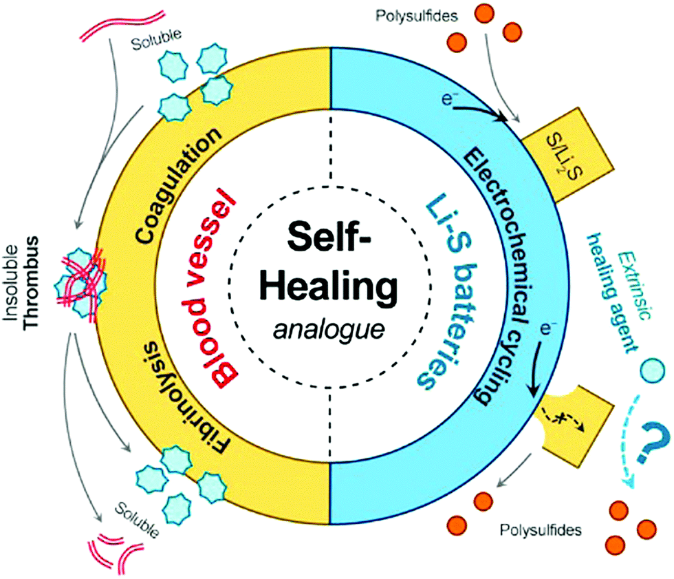 | ||
| Fig. 25 Schematic of healing mechanism for sulfur particle cathodes. (left side) Simplified schematic of coagulation cascade toward formation of thrombus (blood clot) and fibrinolysis of thrombus into soluble fibrin fragments, which are modulated by two trypsins: thrombin and plasmin; (right side) schematic of deposition and dissolution of micrometer-sized sulfur/Li2S particles with limited electrical contact, hindering full electrochemical utilization. To enable the stable and reversible utilization, a complementary route is introduced, through chemical reactions between an extrinsic healing agent in solution and insoluble sulfur compounds. Reprinted with permission from ref. 413. Copyright 2017 American Chemical Society. | ||
Thus, novel healing agents that are smart, sustainable, and rapidly responsive hold future promises. This bio-inspired approach can also be easily implemented in other high-energy electrochemical storage and conversion systems, such as metal–O2 batteries and fuel cells.
5.3 Bio-inspired fuel cells
In terms of fuel cells, nature-inspired or bio-inspired design is utilized in flow fields to circumvent the uneven reactant distribution issue across the catalyst layer, which leads to losses in fuel cell performance. The majority of the reports in the literature are based on the imitation of apparent features of biological structures (such as leaves, veins, etc.), without providing a clear theoretical foundation that allows to capture the underlying physical phenomena.414–418 As a result, the design and channel geometries of these bio-imitating flow fields cannot be systematically reproduced or scaled-up, and are prone to disappointing fuel cell performance.A true bio-inspired design was employed to improve the design of commercial flow fields in fuel cells, whose primary role is the distribution of reactants across the catalyst layer, electron transfer, as well as water and heat management. The human lung serves a similar role in nature; air is uniformly transported through its complex architecture to the bloodstream to oxygenate the blood cells. Its architecture comprises two regions: the dense upper region (bronchi) with 14–16 generations decreases the convective gas flow rate from the bronchial to the acinar airways located in the lower region (7–9 generations), which is dominated by diffusion driven transport, resulting in the production of constant entropy across each level in both regions and, hence, in minimal overall entropy production of the entire lung.101,107–111,419
Prior to the manufacturing of lung-inspired flow fields, modeling simulations were conducted to calculate the optimum number of generations required to ensure uniform distribution of reactants and minimal entropy production, or, in other words, the number of generations required for the convection driven flow to be equal to the diffusion driven flow (Péclet = 1). A detailed model was built in COMSOL, revealing that the ideal number of generations, N, for minimum overall entropy production is equal to 4–7; for N less than 4, gas flow is dominated by convection, whereas for N higher than 8, gas transport is driven by diffusion (Fig. 26C and D).109,352 The same PEFC operating conditions were used in the model and in the experimental measurements, employing flow fields with 10 cm2 surface area, constant fuel cell temperature (70 °C), and three different RH values (50%, 75%, and 100%).
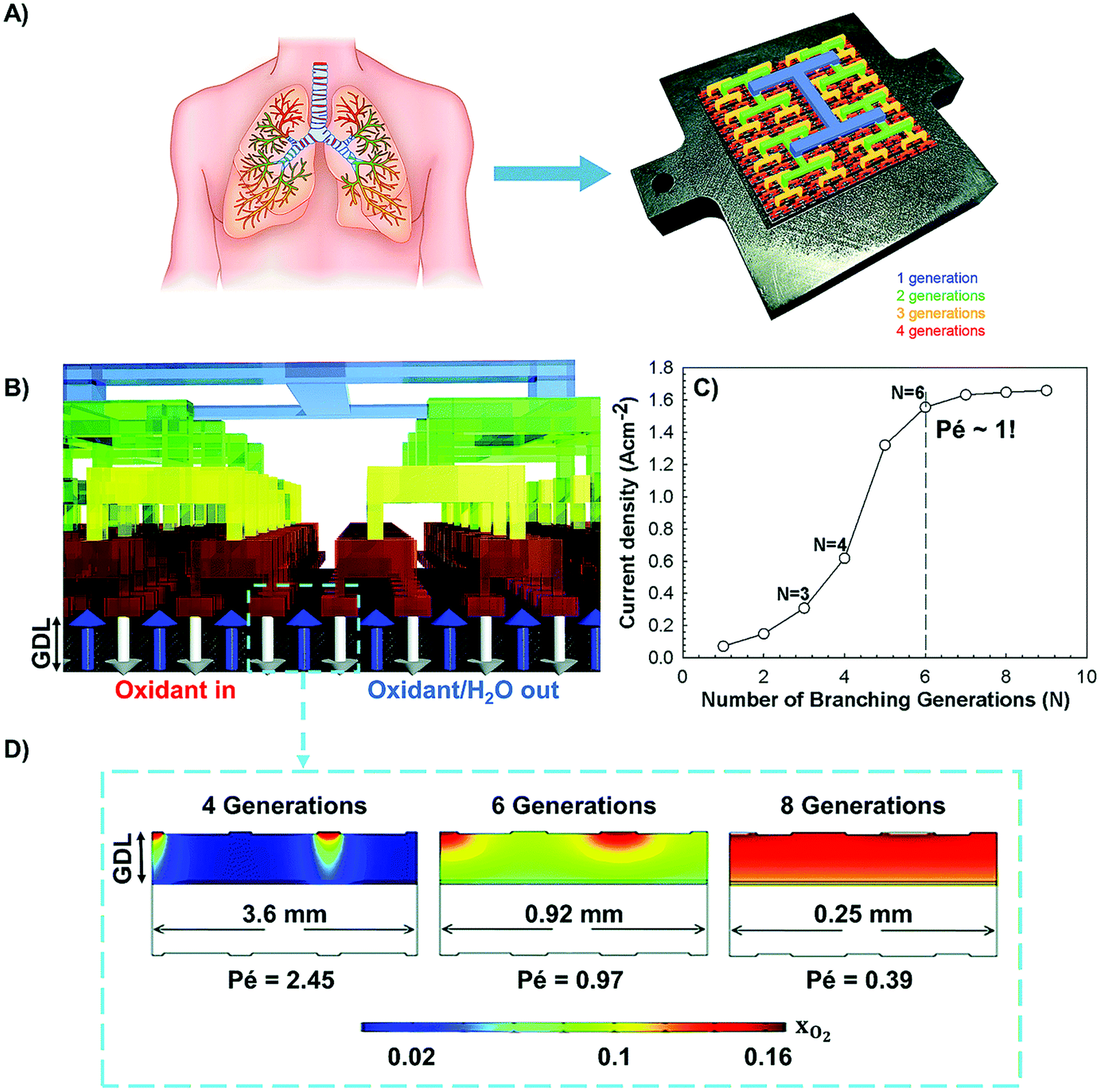 | ||
| Fig. 26 (A) Inspired by nature: the unique characteristics of the lung (fractal structure and minimum entropy production) are implemented into the design of lung-inspired flow fields for PEFCs; (B and D) prior to experimental validation, numerical simulations are conducted to determine the number of generations, N, required to achieve matching convection and diffusion driven flow through the outlets, and (C) uniform reactant distribution. A close-up view of the cathode side of the modeling domain is demonstrated in (B), where white and blue arrows represent the inlet and outlet flow of oxidants to, and oxidants plus formed H2O from the catalyst layer, respectively, and xO2 is the mass fraction of O2. Reproduced from ref. 109 with permission from the Royal Society of Chemistry. | ||
These modeling results served as the basis for the engineering of lung-inspired flow fields with N = 3, 4, and 5 generations via stereolithography, a 3D printing method creating 3D objects from successive layers of sintered steel. Flow fields (10 cm2) with 4 generations exhibited a ∼30% increase in current and power density at 50 and 75% relative humidity (RH), compared to commercial single serpentine flow fields (Fig. 27A–D).109 The positive effect of a fractal structure was also evident in the produced pressure drop, with the lung-inspired flow fields exhibiting ∼75% lower values than their commercial counterparts (less than 2 kPa and ∼5 kPa for lung-inspired and serpentine flow fields, respectively) for each RH tested, minimizing the parasitic losses and enhancing the fuel cell performance. The same pressure drop (less than 2 kPa) was measured when larger lung-inspired flow fields were constructed with 25 cm2 surface area, whereas the high pressure drop of ∼25 kPa measured in serpentine flow fields (25 cm2) was detrimental to their performance.109
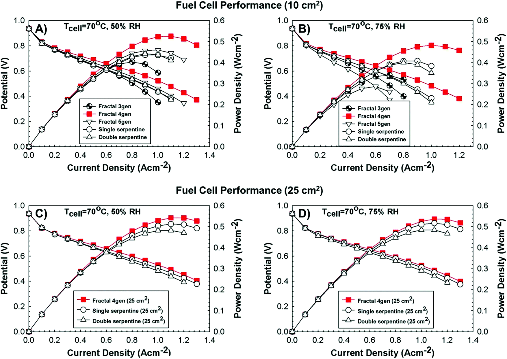 | ||
| Fig. 27 The lung-inspired flow-field based PEFCs, demonstrate improved performance at 50 and 75% RH (N = 4) compared to conventional, serpentine flow-field based PEFCs (A and B); 10 cm2 flow field area. When scaled (25 cm2 flow field area), similar results are obtained for fractal flow fields at 50 and 75% RH (C and D), even though the performance of serpentine flow field based PEFCs is improved, due to an order of magnitude higher pressure drop than fractal flow field based PEFCs. Reproduced from ref. 109 with permission from the Royal Society of Chemistry. | ||
Lung-inspired flow field based PEFCs with N = 3 generations demonstrated the worst performance under all experimental conditions tested, due to the large spacing between adjacent outlets, resulting in insufficiently high reactant concentrations across the catalyst layer.109 On the contrary, lung-inspired flow field based PEFCs with N = 5 generations exhibited a lower performance than commercial single serpentine flow field based PEFCs, since their narrow channels in their final generation were prone to flooding. At high RH conditions (100%), all lung-inspired flow fields were vulnerable to flooding and fuel cell performance deteriorated.109
Their susceptibility to flooding at high humidity conditions (100% RH) was evaluated via neutron radiography of a lung-inspired PEFC (N = 4) during galvanostatic operation at various current densities (0.3, 0.5, and 0.6 A cm−2).420 Neutron images revealed significant water accumulation in the interdigitated outlet channels of the fractal distributor, due to limited convective water removal as a result of narrow channels and slow gas flow in the lung-inspired flow fields. Flooding was mitigated at high current densities (0.5 and 0.6 A cm−2), since faster gas flow and high pressure drop enhanced the rate of water removal, resulting in an instantaneous increase in the potential of over 200 mV (at 0.6 A cm−2 operating current density).420 Such a significant increase in fuel cell performance emphasizes the importance of an unobstructed inlet structure of the lung-inspired flow fields, as any defect in the fractal channel network, and especially in the outlet channels of the fractal distributor, render the inlet channels susceptible to clogging.420
It is evident that apart from a carefully crafted internal structure, the adoption of a water management strategy is required to ensure reliable operation of lung-inspired flow field based PEFCs. Recently, we developed a novel strategy421 for water removal in PEFCs based on the utilization of capillary arrays laser drilled in the land of the flow fields, which allow supply or removal of water depending on the demand of the electrode. A parallel flow-field modified with capillaries exhibited ∼95% and ∼7% improvement in peak power density over the conventional parallel and serpentine flow-fields, respectively.421 This effective water management strategy ensures reliable fuel cell operation and is currently incorporated into lung-inspired flow fields.
The complex 3D structure of lung-inspired flow fields, produced from stainless steel, faces manufacturing and cost challenges, as it necessitates the employment of the expensive and time consuming, laser sintering. Most recently, printed circuit boards422 were used instead, as an alternative, cost-efficient material for the rapid manufacturing of lung-inspired flow fields, resulting in uniform distribution of reactants across the catalyst layer, increased performance compared to single serpentine flow fields and improved water management at high RH.
6. Conclusions and perspective
The design of electrocatalysts with optimized electronic and ionic mobility as well as kinetics at multiphase boundaries is gaining enormous interest in the context of renewable energy and more efficient electrochemical conversions. However, to improve their properties, it is imperative to control their architecture. Nanopores are characterized by a short diffusion length and high multiphase contact, which enlarges the electrochemically active surface area, while macropores enhance the transport properties and kinetics. Hence, the identification and practical use of systematic design principles that guide the chemical properties and structure of electrocatalytic materials to increase activity and stability is crucial.This necessitates the development of multi-scale models that properly consider geometrical, physical and chemical phenomena across all scales. Nature can be an excellent guide to rational design, as it is full of hierarchical structures and biological catalysts that are scalable, efficient, and robust. However, the majority of research that aims to learn from nature to develop new electrocatalysts and devices is based on straightforward biomimicry or “bio-imitation”, which mimics isolated features of biological or non-biological natural structures. This risks to lead to sub-optimal activity and stability, because the difference in context between nature and technology is not accounted for and the actual physical processes that govern the biological organism or system are neglected.
On the contrary, the nature-inspired engineering approach advocated in this review is based on maximizing the fundamental mechanistic understanding of the principles that underpin desired traits, and their context, followed by their appropriate incorporation into the design of new electrocatalysts and electrochemical devices. Nano-, meso-, and macro-scale levels are considered into the design, resulting in the engineering of robust, highly efficient, and scalable electrochemical devices and the synthesis of highly active electrocatalysts with increased surface area, number of active sites, and enhanced charge and mass transport.
At the nanoscale, the structure and function of metalloenzymes is the most popular source of inspiration currently, since they catalyze the same reactions as in electrochemical devices. Even though their synthesis procedure is tedious and time-consuming, the synthesized electrocatalysts exhibit high activity and stability, with enhanced transport properties.
The advocated nature-inspired approach is also utilized in the design of electrochemical devices, where both the meso- and macroscale matter. The fractal network of the human lung serves as the basis for the design of lung-inspired flow fields for polymer electrolyte fuel cells, leading to uniform reactant distribution across the catalyst layer and improved fuel cell performance, compared to commercial single serpentine flow field based PEFCs. In batteries, the thorough study of the structure of the cartilage results in the creation of hierarchical, porous electrodes with high ionic mobility, mechanical flexibility, and resistance to dendrite growth. The investigation of the fibrinolysis reaction within blood vessels serves as the template for the creation of self-healing anodes for Li–S batteries with high faradaic efficiencies and cycling stability, using polysulfides as the healing agent.
Table 4 illustrates the potential of nature-inspired engineering to transform the design of electrocatalysts and electrochemical devices. It summarizes a number of examples on nature-inspired design discussed in this review, including advantages and outstanding challenges.
| Nature-inspired design | Advantages | Challenges |
|---|---|---|
| Electrocatalysts – nanoscale | ||
| Hydrogenase-inspired | • Similar HER & HOR activity to Pt/C | • Long-term stability |
| • High CO2RR activity | • Fuel cell performance tests required | |
| “Murray-inspired” | • Enhanced mass transport | • Scale-up |
| • High ORR & CO2RR activity | • Tedious & time-consuming synthesis procedure (“Murray-inspired”) | |
| Hierarchically structured electrocatalysts – mesoscale | ||
| Optimized pore network | • Enhanced mass transport | • Fuel cell & battery performance tests required. |
| • High catalyst utilization | ||
| • Low catalyst loading | ||
| Devices – macroscale | ||
| Bio-inspired batteries | • Flexibility | • Compatibility of the ion conductive membrane with the electrode |
| • Stability | • Toxicity | |
| • High capacity & conductivity | • Scale-up | |
| Lung-inspired flow fields for PEFCs | • Uniform reactant distribution | • High cost (stainless steel) |
| • Low pressure drop | • More prone to flooding (stainless steel) than commercial PEFCs. Water management strategy required. | |
| • Higher electrocatalyst stability and fuel cell performance than commercial PEFCs | ||
| • Scalable | ||
| • Low cost (PCB) | ||
All these examples demonstrate the diversity of applications of nature-inspired engineering in the electrochemical domain, and its innate ability to provide innovative solutions to engineering challenges, leveraged by parallel advances in synthesis techniques, additive manufacturing, and computational tools. Nature-inspired chemical engineering (NICE) facilitates this process through a systematic methodology for design and innovation, translating nature-inspired concepts to computationally assisted designs, prototypes and implementations.
We are only at the beginning. Because nature contains examples much ahead of current technology in terms of material properties, scalability, and efficiency, with a need to satisfy multiple objectives all at once, it is worthwhile to thoroughly investigate the underlying properties to inspire innovation, and NICE offers a systematic methodology to accomplish this goal.
Abbreviations
Symbol Description| ANF | Aramid nanofiber |
| BFC | Biofuel cell |
| CH4 | Methane |
| C2H4 | Ethylene |
| CO | Carbon monoxide |
| CO2 | Carbon dioxide |
| CODH | CO-dehydrogenase |
| CPG | Copper nanocomposite |
| Cu(phen)2 | Cu2+1,10-phenanthroline |
| D | Fractal dimension |
| d-FAD-GDH | Deglycosylated flavin adenine dinucleotide-dependent glucose dehydrogenase |
| DBU | 1,8-Diazabicyclo[5.4]undec-7-ene |
| DMF | Dimethylformide |
| DNTs | Dendritic nickel trees |
| ECM | Extracellular matrix |
| ECSA | Electrochemically active surface area |
| EFC | Enzymatic fuel cell |
| FDH | Formate dehydrogenase |
| FE | Faradaic efficiency |
| FECO | Faradaic efficiency of carbon monoxide |
| GO | Graphene oxide |
| HCOOH | Formic acid |
| HER | Hydrogen evolution reaction |
| HOR | Hydrogen oxidation reaction |
| LiTFSI | Lithium bis(trifluoromethanesulfonyl)imide |
| m | Number of bifurcation points at each branch of dendritic nickel tree |
| MEA | Membrane electrode assembly |
| M(tpfcBr8) | β-Pyrrole-brominated 5,10,15-tris-pentafluorophenyl-corrole, where M = Mn, Fe, Co, Ni, and Cu |
| MFC | Microbial fuel cell |
| MOF | Metal organic framework |
| MWCNT | Multiwall carbon nanotube |
| n | Number of side branches at each bifurcation |
| NHE | Normal hydrogen electrode |
| NF | Nanofiber |
| NPMC | Non-precious metal electrocatalyst |
| o-Fe2DTPP | Iron tetraphenylporphyrin dimer |
| OER | Oxygen evolution reaction |
| ORR | Oxygen reduction reaction |
| PANI | Polyaniline |
| PEFC | Polymer electrolyte fuel cell |
| PEI | Poly(ethylenimine) |
| PEO | Poly-ethylene oxide |
| PGM | Platinum group metal |
| PPy | Polypyrrole |
| P(GMA-BA-PEGMA) | Poly(glycidyl methacrylate-co-butyl acrylate)-co-poly(ethylene glycol) methacrylate |
| PVP | Polyvinyl pyrrolidone |
| Py13-TFS | N-Propyl-N-methylpyrrolidinium bis(trifluoromethylsulfonyl)imide |
| RDS | Rate determining step |
| RH | Relative humidity |
| RHE | Reversible hydrogen electrode |
| RRDE | Rotating ring disk electrode |
| SHE | Standard hydrogen electrode |
| SEM | Scanning electron microscopy |
| SWCNT | Single wall carbon nanotube |
| TEM | Transmission electron microscopy |
| TMNC | Transition metals supported on nitrogen doped carbon |
| TOF | Turnover frequency |
| TON | Turnover number |
| UAV | Unmanned aerial vehicle |
| XPS | X-ray photoelectron spectroscopy |
| XRD | X-ray diffraction |
Greek letters
| β | Scale factor |
Conflicts of interest
There are no conflicts of interest to declare.Acknowledgements
The authors gratefully acknowledge support from an EPSRC “Frontier Engineering” Grant (EP/K038656/1) and an EPSRC “Frontier Engineering: Progression” Grant (EP/S03305X/1).References
- L. Galvani, De Bononiensi scientiarum et artium instituto atque academia commentarii, 1791, vol. 7, pp. 363–418 Search PubMed.
- A. Volta, Philos. Trans. R. Soc. London, 1800, 90, 403–431 CrossRef.
- R. de Levie, J. Electroanal. Chem., 1999, 476, 92–93 CrossRef CAS.
- S. Trasatti, J. Electroanal. Chem., 1999, 476, 90–91 CrossRef CAS.
- W. R. Grove, Philos. Mag., 1839, 14, 127–130 Search PubMed.
- M. Faraday, Experimental Researches in Electricity, Richard and John Edward Taylor, London, 1849 Search PubMed.
- W. Ostwald, Elektrochemie: Ihre Geschichte und Lehre, Veit and Comp., 1896 Search PubMed.
- J. Greeley and N. M. Markovic, Energy Environ. Sci., 2012, 5, 9246–9256 RSC.
- N. Kobosev and W. Monblanova, Acta Physicochim. URSS, 1934, 1, 611 Search PubMed.
- V. R. Stamenkovic, D. Strmcnik, P. P. Lopes and N. M. Markovic, Nat. Mater., 2016, 16, 57 CrossRef PubMed.
- K. Müller-Dethlefs and P. Hobza, Chem. Rev., 2000, 100, 143–168 CrossRef PubMed.
- D. Strmcnik, K. Kodama, D. van der Vliet, J. Greeley, V. R. Stamenkovic and N. M. Marković, Nat. Chem., 2009, 1, 466–472 CrossRef CAS PubMed.
- M. K. Debe, Nature, 2012, 486, 43–51 CrossRef CAS PubMed.
- Z. W. Seh, J. Kibsgaard, C. F. Dickens, I. Chorkendorff, J. K. Nørskov and T. F. Jaramillo, Science, 2017, 355, eaad4998 CrossRef PubMed.
- Y. Kang, P. Yang, N. M. Markovic and V. R. Stamenkovic, Nano Today, 2016, 11, 587–600 CrossRef CAS.
- E. Yeager, Electrochim. Acta, 1984, 29, 1527–1537 CrossRef CAS.
- G. A. Somorjai, Chem. Rev., 1996, 96, 1223–1236 CrossRef CAS PubMed.
- B. C. H. Steele and A. Heinzel, Nature, 2001, 414, 345–352 CrossRef CAS PubMed.
- P. N. Ross, J. Electrochem. Soc., 1979, 126, 78–82 CrossRef CAS.
- J. D. Benck, T. R. Hellstern, J. Kibsgaard, P. Chakthranont and T. F. Jaramillo, ACS Catal., 2014, 4, 3957–3971 CrossRef CAS.
- Z. L. Wang, T. S. Ahmad and M. A. El-Sayed, Surf. Sci., 1997, 380, 302–310 CrossRef CAS.
- P. Trogadas, T. F. Fuller and P. Strasser, Carbon, 2014, 75, 5–42 CrossRef CAS.
- X. Yu and S. Ye, J. Power Sources, 2007, 172, 133–144 CrossRef CAS.
- X. Yu and S. Ye, J. Power Sources, 2007, 172, 145–154 CrossRef CAS.
- V. S. Bagotzky and A. M. Skundin, Electrochim. Acta, 1984, 29, 757–765 CrossRef.
- J. Escard, C. Leclère and J. P. Contour, J. Catal., 1973, 29, 31–39 CrossRef CAS.
- S. Mukerjee, J. Appl. Electrochem., 1990, 20, 537–548 CrossRef CAS.
- D. Banham and S. Ye, ACS Energy Lett., 2017, 2, 629–638 CrossRef CAS.
- K. M. Caldwell, D. E. Ramaker, Q. Jia, S. Mukerjee, J. M. Ziegelbauer, R. S. Kukreja and A. Kongkanand, J. Phys. Chem. C, 2015, 119, 757–765 CrossRef CAS PubMed.
- H. A. Gasteiger, S. S. Kocha, B. Sompalli and F. T. Wagner, Appl. Catal., B, 2005, 56, 9–35 CrossRef CAS.
- B. Han, C. E. Carlton, A. Kongkanand, R. S. Kukreja, B. R. Theobald, L. Gan, R. O'Malley, P. Strasser, F. T. Wagner and Y. Shao-Horn, Energy Environ. Sci., 2015, 8, 258–266 RSC.
- C. Wang, M. Chi, D. Li, D. Strmcnik, D. van der Vliet, G. Wang, V. Komanicky, K.-C. Chang, A. P. Paulikas, D. Tripkovic, J. Pearson, K. L. More, N. M. Markovic and V. R. Stamenkovic, J. Am. Chem. Soc., 2011, 133, 14396–14403 CrossRef CAS PubMed.
- T. Yoshida and K. Kojima, Electrochem. Soc. Interface, 2015, 24, 45–49 CrossRef CAS.
- A. U. Nilekar, Y. Xu, J. Zhang, M. B. Vukmirovic, K. Sasaki, R. R. Adzic and M. Mavrikakis, Top. Catal., 2007, 46, 276–284 CrossRef CAS.
- V. R. Stamenkovic, B. Fowler, B. S. Mun, G. Wang, P. N. Ross, C. A. Lucas and N. M. Marković, Science, 2007, 315, 493–497 CrossRef CAS PubMed.
- V. R. Stamenkovic, B. S. Mun, M. Arenz, K. J. J. Mayrhofer, C. A. Lucas, G. Wang, P. N. Ross and N. M. Markovic, Nat. Mater., 2007, 6, 241–247 CrossRef CAS PubMed.
- V. Jalan and E. J. Taylor, J. Electrochem. Soc., 1983, 130, 2299–2302 CrossRef CAS.
- N. Markovic, H. Gasteiger and P. N. Ross, J. Electrochem. Soc., 1997, 144, 1591–1597 CrossRef CAS.
- N. M. Markovic, H. A. Gasteiger and P. N. Ross, J. Phys. Chem., 1995, 99, 3411–3415 CrossRef CAS.
- M. T. Paffett, J. G. Beery and S. Gottesfeld, J. Electrochem. Soc., 1988, 135, 1431–1436 CrossRef CAS.
- U. A. Paulus, A. Wokaun, G. G. Scherer, T. J. Schmidt, V. Stamenkovic, N. M. Markovic and P. N. Ross, Electrochim. Acta, 2002, 47, 3787–3798 CrossRef CAS.
- V. Stamenković, T. J. Schmidt, P. N. Ross and N. M. Marković, J. Phys. Chem. B, 2002, 106, 11970–11979 CrossRef.
- M. F. Mathias, R. Makharia, H. A. Gasteiger, J. J. Conley, T. J. Fuller, C. J. Gittleman, S. S. Kocha, D. P. Miller, C. K. Mittelsteadt, T. Xie, S. G. Yan and P. T. Yu, Electrochem. Soc. Interface, 2005, 14, 24–35 CAS.
- K. J. J. Mayrhofer, K. Hartl, V. Juhart and M. Arenz, J. Am. Chem. Soc., 2009, 131, 16348–16349 CrossRef CAS PubMed.
- P. J. Ferreira, G. J. la O’, Y. Shao-Horn, D. Morgan, R. Makharia, S. Kocha and H. A. Gasteiger, J. Electrochem. Soc., 2005, 152, A2256–A2271 CrossRef.
- Y. Shao-Horn, W. C. Sheng, S. Chen, P. J. Ferreira, E. F. Holby and D. Morgan, Top. Catal., 2007, 46, 285–305 CrossRef CAS.
- D. Wang, Y. Yu, H. L. Xin, R. Hovden, P. Ercius, J. A. Mundy, H. Chen, J. H. Richard, D. A. Muller, F. J. DiSalvo and H. D. Abruña, Nano Lett., 2012, 12, 5230–5238 CrossRef CAS PubMed.
- J. Erlebacher, M. J. Aziz, A. Karma, N. Dimitrov and K. Sieradzki, Nature, 2001, 410, 450–453 CrossRef CAS PubMed.
- J. Rugolo, J. Erlebacher and K. Sieradzki, Nat. Mater., 2006, 5, 946–949 CrossRef CAS PubMed.
- R. Wang, H. Wang, F. Luo and S. Liao, Electrochem. Energy Rev., 2018, 1, 324–387 CrossRef CAS.
- R. Jiang, S. O. Tung, Z. Tang, L. Li, L. Ding, X. Xi, Y. Liu, L. Zhang and J. Zhang, Energy Storage Mater., 2018, 12, 260–276 CrossRef.
- A. Kongkanand and M. F. Mathias, J. Phys. Chem. Lett., 2016, 7, 1127–1137 CrossRef CAS PubMed.
- N. Nonoyama, S. Okazaki, A. Z. Weber, Y. Ikogi and T. Yoshida, J. Electrochem. Soc., 2011, 158, B416–B423 CrossRef CAS.
- A. Kongkanand, N. P. Subramanian, Y. Yu, Z. Liu, H. Igarashi and D. A. Muller, ACS Catal., 2016, 6, 1578–1583 CrossRef CAS.
- N. M. Marković, R. R. Adžić, B. D. Cahan and E. B. Yeager, J. Electroanal. Chem., 1994, 377, 249–259 CrossRef.
- G. A. Somorjai and C. J. Kliewer, React. Kinet. Catal. Lett., 2009, 96, 191–208 CrossRef CAS.
- Y.-J. Wang, W. Long, L. Wang, R. Yuan, A. Ignaszak, B. Fang and D. P. Wilkinson, Energy Environ. Sci., 2018, 11, 258–275 RSC.
- J. Feng, F. Lv, W. Zhang, P. Li, K. Wang, C. Yang, B. Wang, Y. Yang, J. Zhou, F. Lin, G.-C. Wang and S. Guo, Adv. Mater., 2017, 29, 1703798 CrossRef PubMed.
- Y. Jiao, Y. Zheng, M. Jaroniec and S. Z. Qiao, Chem. Soc. Rev., 2015, 44, 2060–2086 RSC.
- I. Ledezma-Yanez, W. D. Z. Wallace, P. Sebastián-Pascual, V. Climent, J. M. Feliu and M. T. M. Koper, Nat. Energy, 2017, 2, 17031 CrossRef CAS.
- P. Wang, X. Zhang, J. Zhang, S. Wan, S. Guo, G. Lu, J. Yao and X. Huang, Nat. Commun., 2017, 8, 14580 CrossRef CAS PubMed.
- J. Chang, L. Feng, C. Liu, W. Xing and X. Hu, Angew. Chem., Int. Ed., 2014, 53, 122–126 CrossRef CAS PubMed.
- G.-T. Fu, C. Liu, Q. Zhang, Y. Chen and Y.-W. Tang, Sci. Rep., 2015, 5, 13703 CrossRef PubMed.
- D. Li, C. Wang, D. S. Strmcnik, D. V. Tripkovic, X. Sun, Y. Kang, M. Chi, J. D. Snyder, D. van der Vliet, Y. Tsai, V. R. Stamenkovic, S. Sun and N. M. Markovic, Energy Environ. Sci., 2014, 7, 4061–4069 RSC.
- H.-L. Jiang, T. Akita, T. Ishida, M. Haruta and Q. Xu, J. Am. Chem. Soc., 2011, 133, 1304–1306 CrossRef CAS PubMed.
- S. Guo, S. Zhang and S. Sun, Angew. Chem., Int. Ed., 2013, 52, 8526–8544 CrossRef CAS PubMed.
- J. Wu and H. Yang, Nano Res., 2011, 4, 72–82 CrossRef CAS.
- J. Wu and H. Yang, Acc. Chem. Res., 2013, 46, 1848–1857 CrossRef CAS PubMed.
- J. Wu, J. Zhang, Z. Peng, S. Yang, F. T. Wagner and H. Yang, J. Am. Chem. Soc., 2010, 132, 4984–4985 CrossRef CAS PubMed.
- S.-I. Choi, M. Shao, N. Lu, A. Ruditskiy, H.-C. Peng, J. Park, S. Guerrero, J. Wang, M. J. Kim and Y. Xia, ACS Nano, 2014, 8, 10363–10371 CrossRef CAS PubMed.
- N. Becknell, Y. Kang, C. Chen, J. Resasco, N. Kornienko, J. Guo, N. M. Markovic, G. A. Somorjai, V. R. Stamenkovic and P. Yang, J. Am. Chem. Soc., 2015, 137, 15817–15824 CrossRef CAS PubMed.
- Y. Wu, D. Wang, G. Zhou, R. Yu, C. Chen and Y. Li, J. Am. Chem. Soc., 2014, 136, 11594–11597 CrossRef CAS PubMed.
- F. Godínez-Salomón, R. Mendoza-Cruz, M. J. Arellano-Jimenez, M. Jose-Yacaman and C. P. Rhodes, ACS Appl. Mater. Interfaces, 2017, 9, 18660–18674 CrossRef PubMed.
- S. Luo, M. Tang, P. K. Shen and S. Ye, Adv. Mater., 2017, 29, 1601687 Search PubMed.
- Z. Fang, Y. Wang, C. Liu, S. Chen, W. Sang, C. Wang and J. Zeng, Small, 2015, 11, 2593–2605 CrossRef CAS PubMed.
- J. Ding, L. Bu, S. Guo, Z. Zhao, E. Zhu, Y. Huang and X. Huang, Nano Lett., 2016, 16, 2762–2767 CrossRef CAS PubMed.
- Z. Zhang, Z. Luo, B. Chen, C. Wei, J. Zhao, J. Chen, X. Zhang, Z. Lai, Z. Fan, C. Tan, M. Zhao, Q. Lu, B. Li, Y. Zong, C. Yan, G. Wang, Z. J. Xu and H. Zhang, Adv. Mater., 2016, 28, 8712–8717 CrossRef CAS PubMed.
- J. Park, H. Wang, M. Vara and Y. Xia, ChemSusChem, 2016, 9, 2855–2861 CrossRef CAS PubMed.
- J. Snyder, T. Fujita, M. W. Chen and J. Erlebacher, Nat. Mater., 2010, 9, 904 CrossRef CAS PubMed.
- J. Snyder, K. Livi and J. Erlebacher, Adv. Funct. Mater., 2013, 23, 5494–5501 CrossRef CAS.
- D. Banham, S. Ye, K. Pei, J.-i. Ozaki, T. Kishimoto and Y. Imashiro, J. Power Sources, 2015, 285, 334–348 CrossRef CAS.
- A. A. Gewirth, J. A. Varnell and A. M. DiAscro, Chem. Rev., 2018, 118, 2313–2339 CrossRef CAS PubMed.
- D. Liu, L. Tao, D. Yan, Y. Zou and S. Wang, ChemElectroChem, 2018, 5, 1775–1785 CrossRef CAS.
- E. Proietti, F. Jaouen, M. Lefèvre, N. Larouche, J. Tian, J. Herranz and J.-P. Dodelet, Nat. Commun., 2011, 2, 416 CrossRef PubMed.
- J. Shui, C. Chen, L. Grabstanowicz, D. Zhao and D.-J. Liu, Proc. Natl. Acad. Sci. U. S. A., 2015, 112, 10629–10634 CrossRef CAS PubMed.
- Y. Wang, J. Li and Z. Wei, ChemElectroChem, 2018, 5, 1764–1774 CrossRef CAS.
- F. Jaouen, E. Proietti, M. Lefèvre, R. Chenitz, J.-P. Dodelet, G. Wu, H. T. Chung, C. M. Johnston and P. Zelenay, Energy Environ. Sci., 2011, 4, 114–130 RSC.
- D. Malko, T. Lopes, E. Symianakis and A. R. Kucernak, J. Mater. Chem. A, 2016, 4, 142–152 RSC.
- T. Reshetenko, A. Serov, K. Artyushkova, I. Matanovic, S. Sarah and P. Atanassov, J. Power Sources, 2016, 324, 556–571 CrossRef CAS.
- M. Shao, Q. Chang, J.-P. Dodelet and R. Chenitz, Chem. Rev., 2016, 116, 3594–3657 CrossRef CAS PubMed.
- B. Y. Xia, Y. Yan, N. Li, H. B. Wu, X. W. Lou and X. Wang, Nat. Energy, 2016, 1, 15006 CrossRef CAS.
- R. Zhou, M. Jaroniec and S.-Z. Qiao, ChemCatChem, 2015, 7, 3808–3817 CrossRef CAS.
- A. Sarapuu, E. Kibena-Põldsepp, M. Borghei and K. Tammeveski, J. Mater. Chem. A, 2018, 6, 776–804 RSC.
- V. V. Strelko, N. T. Kartel, I. N. Dukhno, V. S. Kuts, R. B. Clarkson and B. M. Odintsov, Surf. Sci., 2004, 548, 281–290 CrossRef CAS.
- H. Tan, J. Tang, J. Kim, Y. V. Kaneti, Y.-M. Kang, Y. Sugahara and Y. Yamauchi, J. Mater. Chem. A, 2019, 7, 1380–1393 RSC.
- B. Liu, H. Shioyama, T. Akita and Q. Xu, J. Am. Chem. Soc., 2008, 130, 5390–5391 CrossRef CAS PubMed.
- C. Wang, D. Liu and W. Lin, J. Am. Chem. Soc., 2013, 135, 13222–13234 CrossRef CAS PubMed.
- O. M. Yaghi, M. O'Keeffe, N. W. Ockwig, H. K. Chae, M. Eddaoudi and J. Kim, Nature, 2003, 423, 705–714 CrossRef CAS PubMed.
- Z.-S. Wu, L. Chen, J. Liu, K. Parvez, H. Liang, J. Shu, H. Sachdev, R. Graf, X. Feng and K. Müllen, Adv. Mater., 2014, 26, 1450–1455 CrossRef CAS PubMed.
- D. Zhao, J.-L. Shui, L. R. Grabstanowicz, C. Chen, S. M. Commet, T. Xu, J. Lu and D.-J. Liu, Adv. Mater., 2014, 26, 1093–1097 CrossRef CAS PubMed.
- P. Trogadas, V. Ramani, P. Strasser, T. F. Fuller and M.-O. Coppens, Angew. Chem., Int. Ed., 2016, 55, 122–148 CrossRef CAS PubMed.
- Y.-J. Wang, D. P. Wilkinson and J. Zhang, Chem. Rev., 2011, 111, 7625–7651 CrossRef CAS PubMed.
- D.-W. Wang and D. Su, Energy Environ. Sci., 2014, 7, 576–591 RSC.
- G. Wu and P. Zelenay, Acc. Chem. Res., 2013, 46, 1878–1889 CrossRef CAS PubMed.
- Z. Niu, N. Becknell, Y. Yu, D. Kim, C. Chen, N. Kornienko, G. A. Somorjai and P. Yang, Nat. Mater., 2016, 15, 1188 CrossRef CAS PubMed.
- M.-O. Coppens, Curr. Opin. Chem. Eng., 2012, 1, 281–289 CrossRef CAS.
- S. Gheorghiu and M.-O. Coppens, AIChE J., 2004, 50, 812–820 CrossRef CAS.
- S. Gheorghiu, S. Kjelstrup, P. Pfeifer and M. O. Coppens, in Fractals in Biology and Medicine, ed. G. A. Losa, D. Merlini, T. F. Nonnenmacher and E. R. Weibel, Birkhäuser Basel, Basel, 2005, pp. 31–42 Search PubMed.
- P. Trogadas, J. I. S. Cho, T. P. Neville, J. Marquis, B. Wu, D. J. L. Brett and M. O. Coppens, Energy Environ. Sci., 2018, 11, 136–143 RSC.
- P. Trogadas and M.-O. Coppens, in Sustainable Nanoscale Engineering, ed. G. Szekely and A. Livingston, Elsevier, 2020, pp. 19–31 Search PubMed.
- P. Trogadas, M. M. Nigra and M.-O. Coppens, New J. Chem., 2016, 40, 4016–4026 RSC.
- C. D. Murray, Proc. Natl. Acad. Sci. U. S. A., 1926, 12, 207–214 CrossRef CAS PubMed.
- C. D. Murray, J. Gen. Physiol., 1926, 9, 835–841 CrossRef CAS PubMed.
- C. D. Murray, Proc. Natl. Acad. Sci. U. S. A., 1926, 12, 299–304 CrossRef CAS PubMed.
- C. D. Murray, J. Gen. Physiol., 1927, 10, 725–729 CrossRef CAS PubMed.
- L. M. Diener, J. Chem. Educ., 2010, 87, 130–132 CrossRef CAS.
- B. E. Barton and T. B. Rauchfuss, J. Am. Chem. Soc., 2010, 132, 14877–14885 CrossRef CAS PubMed.
- P. Chenevier, L. Mugherli, S. Darbe, L. Darchy, S. DiManno, P. D. Tran, F. Valentino, M. Iannello, A. Volbeda, C. Cavazza and V. Artero, C. R. Chim., 2013, 16, 491–505 CrossRef CAS.
- V. Fourmond, S. Canaguier, B. Golly, M. J. Field, M. Fontecave and V. Artero, Energy Environ. Sci., 2011, 4, 2417–2427 RSC.
- D. Schilter, M. J. Nilges, M. Chakrabarti, P. A. Lindahl, T. B. Rauchfuss and M. Stein, Inorg. Chem., 2012, 51, 2338–2348 CrossRef CAS PubMed.
- A. Ciaccafava, P. Infossi, M.-T. Giudici-Orticoni and E. Lojou, Langmuir, 2010, 26, 18534–18541 CrossRef CAS PubMed.
- S. Ogo, R. Kabe, K. Uehara, B. Kure, T. Nishimura, S. C. Menon, R. Harada, S. Fukuzumi, Y. Higuchi, T. Ohhara, T. Tamada and R. Kuroki, Science, 2007, 316, 585–587 CrossRef CAS PubMed.
- M. Rakowski DuBois and D. L. DuBois, Chem. Soc. Rev., 2009, 38, 62–72 RSC.
- U. J. Kilgore, J. A. S. Roberts, D. H. Pool, A. M. Appel, M. P. Stewart, M. R. DuBois, W. G. Dougherty, W. S. Kassel, R. M. Bullock and D. L. DuBois, J. Am. Chem. Soc., 2011, 133, 5861–5872 CrossRef CAS PubMed.
- A. Dutta, D. L. DuBois, J. A. S. Roberts and W. J. Shaw, Proc. Natl. Acad. Sci. U. S. A., 2014, 111, 16286–16291 CrossRef CAS PubMed.
- N. Coutard, N. Kaeffer and V. Artero, Chem. Commun., 2016, 52, 13728–13748 RSC.
- A. Le Goff, V. Artero, B. Jousselme, P. D. Tran, N. Guillet, R. Métayé, A. Fihri, S. Palacin and M. Fontecave, Science, 2009, 326, 1384–1387 CrossRef CAS PubMed.
- E. Lojou, Electrochim. Acta, 2011, 56, 10385–10397 CrossRef CAS.
- D. Millo, M.-E. Pandelia, T. Utesch, N. Wisitruangsakul, M. A. Mroginski, W. Lubitz, P. Hildebrandt and I. Zebger, J. Phys. Chem. B, 2009, 113, 15344–15351 CrossRef CAS PubMed.
- C. Gutiérrez-Sánchez, D. Olea, M. Marques, V. M. Fernández, I. A. C. Pereira, M. Vélez and A. L. De Lacey, Langmuir, 2011, 27, 6449–6457 CrossRef PubMed.
- F. A. Armstrong, N. A. Belsey, J. A. Cracknell, G. Goldet, A. Parkin, E. Reisner, K. A. Vincent and A. F. Wait, Chem. Soc. Rev., 2009, 38, 36–51 RSC.
- H. Lv, D. Li, D. Strmcnik, A. P. Paulikas, N. M. Markovic and V. R. Stamenkovic, Nano Energy, 2016, 29, 149–165 CrossRef CAS.
- O. Antoine, Y. Bultel and R. Durand, J. Electroanal. Chem., 2001, 499, 85–94 CrossRef CAS.
- I. Katsounaros, W. B. Schneider, J. C. Meier, U. Benedikt, P. U. Biedermann, A. A. Auer and K. J. J. Mayrhofer, Phys. Chem. Chem. Phys., 2012, 14, 7384–7391 RSC.
- Y. Nie, L. Li and Z. Wei, Chem. Soc. Rev., 2015, 44, 2168–2201 RSC.
- J. K. Nørskov, J. Rossmeisl, A. Logadottir, L. Lindqvist, J. R. Kitchin, T. Bligaard and H. Jónsson, J. Phys. Chem. B, 2004, 108, 17886–17892 CrossRef.
- D. B. Sepa, M. V. Vojnovic and A. Damjanovic, Electrochim. Acta, 1981, 26, 781–793 CrossRef CAS.
- W. Xia, A. Mahmood, Z. Liang, R. Zou and S. Guo, Angew. Chem., Int. Ed., 2016, 55, 2650–2676 CrossRef CAS PubMed.
- Y. Zheng, Y. Jiao, M. Jaroniec, Y. Jin and S. Z. Qiao, Small, 2012, 8, 3550–3566 CrossRef CAS PubMed.
- M. Zhou, H.-L. Wang and S. Guo, Chem. Soc. Rev., 2016, 45, 1273–1307 RSC.
- M. J. Janik, C. D. Taylor and M. Neurock, J. Electrochem. Soc., 2009, 156, B126–B135 CrossRef CAS.
- A. B. Anderson and T. V. Albu, Electrochem. Commun., 1999, 1, 203–206 CrossRef CAS.
- A. B. Anderson and T. V. Albu, J. Electrochem. Soc., 2000, 147, 4229–4238 CrossRef CAS.
- A. B. Anderson, J. Roques, S. Mukerjee, V. S. Murthi, N. M. Markovic and V. Stamenkovic, J. Phys. Chem. B, 2005, 109, 1198–1203 CrossRef CAS PubMed.
- T. Zhang and A. B. Anderson, Electrochim. Acta, 2007, 53, 982–989 CrossRef CAS.
- V. Stamenkovic, B. S. Mun, K. J. J. Mayrhofer, P. N. Ross, N. M. Markovic, J. Rossmeisl, J. Greeley and J. K. Nørskov, Angew. Chem., Int. Ed., 2006, 45, 2897–2901 CrossRef CAS PubMed.
- V. Tripković, E. Skúlason, S. Siahrostami, J. K. Nørskov and J. Rossmeisl, Electrochim. Acta, 2010, 55, 7975–7981 CrossRef.
- R. Gutzler, S. Stepanow, D. Grumelli, M. Lingenfelder and K. Kern, Acc. Chem. Res., 2015, 48, 2132–2139 CrossRef CAS PubMed.
- M. L. Pegis, C. F. Wise, D. J. Martin and J. M. Mayer, Chem. Rev., 2018, 118, 2340–2391 CrossRef CAS PubMed.
- W. Zhang, W. Lai and R. Cao, Chem. Rev., 2017, 117, 3717–3797 CrossRef CAS PubMed.
- R. Baker, D. P. Wilkinson and J. Zhang, Electrochim. Acta, 2009, 54, 3098–3102 CrossRef CAS.
- R. Bashyam and P. Zelenay, Nature, 2006, 443, 63–66 CrossRef CAS PubMed.
- F. Jaouen, J. Herranz, M. Lefèvre, J.-P. Dodelet, U. I. Kramm, I. Herrmann, P. Bogdanoff, J. Maruyama, T. Nagaoka, A. Garsuch, J. R. Dahn, T. Olson, S. Pylypenko, P. Atanassov and E. A. Ustinov, ACS Appl. Mater. Interfaces, 2009, 1, 1623–1639 CrossRef CAS PubMed.
- R. Jasinski, Nature, 1964, 201, 1212–1213 CrossRef CAS.
- I. Ponce, J. F. Silva, R. Oñate, M. C. Rezende, M. A. Paez, J. H. Zagal, J. Pavez, F. Mendizabal, S. Miranda-Rojas, A. Muñoz-Castro and R. Arratia-Pérez, J. Phys. Chem. C, 2012, 116, 15329–15341 CrossRef CAS.
- F. Sedona, M. Di Marino, D. Forrer, A. Vittadini, M. Casarin, A. Cossaro, L. Floreano, A. Verdini and M. Sambi, Nat. Mater., 2012, 11, 970–977 CrossRef CAS PubMed.
- G. Wu, K. L. More, C. M. Johnston and P. Zelenay, Science, 2011, 332, 443–447 CrossRef CAS PubMed.
- J. H. Zagal, Coord. Chem. Rev., 1992, 119, 89–136 CrossRef CAS.
- D. Hötger, M. Etzkorn, C. Morchutt, B. Wurster, J. Dreiser, S. Stepanow, D. Grumelli, R. Gutzler and K. Kern, Phys. Chem. Chem. Phys., 2019, 21, 2587–2594 RSC.
- J. P. Collman, M. Marrocco, P. Denisevich, C. Koval and F. C. Anson, J. Electroanal. Chem. Interfacial Electrochem., 1979, 101, 117–122 CrossRef CAS.
- J. Maruyama, C. Baier, H. Wolfschmidt, P. Bele and U. Stimming, Electrochim. Acta, 2012, 63, 16–21 CrossRef CAS.
- C. Shi and F. C. Anson, Inorg. Chem., 1998, 37, 1037–1043 CrossRef CAS.
- C. Shi, B. Steiger, M. Yuasa and F. C. Anson, Inorg. Chem., 1997, 36, 4294–4295 CrossRef CAS PubMed.
- K. Shigehara and F. C. Anson, J. Phys. Chem., 1982, 86, 2776–2783 CrossRef CAS.
- D. J. Wasylenko, C. Rodríguez, M. L. Pegis and J. M. Mayer, J. Am. Chem. Soc., 2014, 136, 12544–12547 CrossRef CAS PubMed.
- S. Yoshimoto, J. Inukai, A. Tada, T. Abe, T. Morimoto, A. Osuka, H. Furuta and K. Itaya, J. Phys. Chem. B, 2004, 108, 1948–1954 CrossRef CAS.
- S. Yoshimoto, A. Tada, K. Suto, R. Narita and K. Itaya, Langmuir, 2003, 19, 672–677 CrossRef CAS.
- J. P. Collman, P. S. Wagenknecht and J. E. Hutchison, Angew. Chem., Int. Ed. Engl., 1994, 33, 1537–1554 CrossRef.
- E. Song, C. Shi and F. C. Anson, Langmuir, 1998, 14, 4315–4321 CrossRef CAS.
- P. Garrido-Barros, C. Gimbert-Suriñach, R. Matheu, X. Sala and A. Llobet, Chem. Soc. Rev., 2017, 46, 6088–6098 RSC.
- A. Morozan, S. Campidelli, A. Filoramo, B. Jousselme and S. Palacin, Carbon, 2011, 49, 4839–4847 CrossRef CAS.
- N. J. Tao, Phys. Rev. Lett., 1996, 76, 4066–4069 CrossRef CAS PubMed.
- S. Yoshimoto, Y. Ono, K. Nishiyama and I. Taniguchi, Phys. Chem. Chem. Phys., 2010, 12, 14442–14444 RSC.
- S. Stepanow, M. Lingenfelder, A. Dmitriev, H. Spillmann, E. Delvigne, N. Lin, X. Deng, C. Cai, J. V. Barth and K. Kern, Nat. Mater., 2004, 3, 229–233 CrossRef CAS PubMed.
- J. P. Collman, R. A. Decréau, H. Lin, A. Hosseini, Y. Yang, A. Dey and T. A. Eberspacher, Proc. Natl. Acad. Sci. U. S. A., 2009, 106, 7320–7323 CrossRef CAS PubMed.
- J. P. Collman, R. A. Decréau, Y. Yan, J. Yoon and E. I. Solomon, J. Am. Chem. Soc., 2007, 129, 5794–5795 CrossRef CAS PubMed.
- S. Ferguson-Miller and G. T. Babcock, Chem. Rev., 1996, 96, 2889–2908 CrossRef CAS PubMed.
- F. L. Sousa, R. J. Alves, M. A. Ribeiro, J. B. Pereira-Leal, M. Teixeira and M. M. Pereira, Biochim. Biophys. Acta, Bioenerg., 2012, 1817, 629–637 CrossRef CAS PubMed.
- S. Yoshikawa, K. Muramoto and K. Shinzawa-Itoh, Annu. Rev. Biophys., 2011, 40, 205–223 CrossRef CAS PubMed.
- S. Bhunia, A. Rana, P. Roy, D. J. Martin, M. L. Pegis, B. Roy and A. Dey, J. Am. Chem. Soc., 2018, 140, 9444–9457 CrossRef CAS PubMed.
- C. T. Carver, B. D. Matson and J. M. Mayer, J. Am. Chem. Soc., 2012, 134, 5444–5447 CrossRef CAS PubMed.
- B. D. Matson, C. T. Carver, A. Von Ruden, J. Y. Yang, S. Raugei and J. M. Mayer, Chem. Commun., 2012, 48, 11100–11102 RSC.
- K. Mittra, S. Chatterjee, S. Samanta and A. Dey, Inorg. Chem., 2013, 52, 14317–14325 CrossRef CAS PubMed.
- M. L. Rigsby, D. J. Wasylenko, M. L. Pegis and J. M. Mayer, J. Am. Chem. Soc., 2015, 137, 4296–4299 CrossRef CAS PubMed.
- S. Samanta, K. Sengupta, K. Mittra, S. Bandyopadhyay and A. Dey, Chem. Commun., 2012, 48, 7631–7633 RSC.
- S. Sinha, M. S. Aaron, J. Blagojevic and J. J. Warren, Chem. – Eur. J., 2015, 21, 18072–18075 CrossRef CAS PubMed.
- P.-J. Wei, G.-Q. Yu, Y. Naruta and J.-G. Liu, Angew. Chem., Int. Ed., 2014, 53, 6659–6663 CrossRef CAS PubMed.
- J. P. Collman, P. Denisevich, Y. Konai, M. Marrocco, C. Koval and F. C. Anson, J. Am. Chem. Soc., 1980, 102, 6027–6036 CrossRef CAS.
- M. Lions, J. B. Tommasino, R. Chattot, B. Abeykoon, N. Guillou, T. Devic, A. Demessence, L. Cardenas, F. Maillard and A. Fateeva, Chem. Commun., 2017, 53, 6496–6499 RSC.
- W.-Y. Gao, M. Chrzanowski and S. Ma, Chem. Soc. Rev., 2014, 43, 5841–5866 RSC.
- N. Zion, A. Friedman, N. Levy and L. Elbaz, Adv. Mater., 2018, 30, 1800406 CrossRef PubMed.
- H.-C. Huang, I. Shown, S.-T. Chang, H.-C. Hsu, H.-Y. Du, M.-C. Kuo, K.-T. Wong, S.-F. Wang, C.-H. Wang, L.-C. Chen and K.-H. Chen, Adv. Funct. Mater., 2012, 22, 3500–3508 CrossRef CAS.
- K. M. Kadish, L. Frémond, Z. Ou, J. Shao, C. Shi, F. C. Anson, F. Burdet, C. P. Gros, J.-M. Barbe and R. Guilard, J. Am. Chem. Soc., 2005, 127, 5625–5631 CrossRef CAS PubMed.
- N. Levy, A. Mahammed, A. Friedman, B. Gavriel, Z. Gross and L. Elbaz, ChemCatChem, 2016, 8, 2832–2837 CrossRef CAS.
- B. Li, Z. Ou, D. Meng, J. Tang, Y. Fang, R. Liu and K. M. Kadish, J. Inorg. Biochem., 2014, 136, 130–139 CrossRef CAS PubMed.
- A. Mahammed, B. Mondal, A. Rana, A. Dey and Z. Gross, Chem. Commun., 2014, 50, 2725–2727 RSC.
- Z. Ou, A. Lü, D. Meng, S. Huang, Y. Fang, G. Lu and K. M. Kadish, Inorg. Chem., 2012, 51, 8890–8896 CrossRef CAS PubMed.
- A. Schechter, M. Stanevsky, A. Mahammed and Z. Gross, Inorg. Chem., 2012, 51, 22–24 CrossRef CAS PubMed.
- N. Levy, A. Mahammed, M. Kosa, D. T. Major, Z. Gross and L. Elbaz, Angew. Chem., Int. Ed., 2015, 54, 14080–14084 CrossRef CAS PubMed.
- N. Levy, J. S. Shpilman, H. C. Honig, D. T. Major and L. Elbaz, Chem. Commun., 2017, 53, 12942–12945 RSC.
- Z. Wang, H. Lei, R. Cao and M. Zhang, Electrochim. Acta, 2015, 171, 81–88 CrossRef CAS.
- Y.-M. Zhao, G.-Q. Yu, F.-F. Wang, P.-J. Wei and J.-G. Liu, Chem. – Eur. J., 2019, 25, 3726–3739 CrossRef CAS PubMed.
- J. M. Le and K. L. Bren, ACS Energy Lett., 2019, 4, 2168–2180 CrossRef CAS.
- T. F. Sherman, J. Gen. Physiol., 1981, 78, 431–453 CrossRef CAS PubMed.
- X. Zheng, G. Shen, C. Wang, Y. Li, D. Dunphy, T. Hasan, C. J. Brinker and B.-L. Su, Nat. Commun., 2017, 8, 14921 CrossRef CAS PubMed.
- C. Deng, K.-H. Wu, J. Scott, S. Zhu, X. Zheng, R. Amal and D.-W. Wang, ACS Appl. Mater. Interfaces, 2019, 11, 9925–9933 CrossRef CAS PubMed.
- M. Bajdich, M. García-Mota, A. Vojvodic, J. K. Nørskov and A. T. Bell, J. Am. Chem. Soc., 2013, 135, 13521–13530 CrossRef CAS PubMed.
- Y. Bi, Z. Cai, D. Zhou, Y. Tian, Q. Zhang, Q. Zhang, Y. Kuang, Y. Li, X. Sun and X. Duan, J. Catal., 2018, 358, 100–107 CrossRef CAS.
- T. Li, B. Xue, B. Wang, G. Guo, D. Han, Y. Yan and A. Dong, J. Am. Chem. Soc., 2017, 139, 12133–12136 CrossRef CAS PubMed.
- E. Kim, M. E. Helton, I. M. Wasser, K. D. Karlin, S. Lu, H.-w. Huang, P. Moënne-Loccoz, C. D. Incarvito, A. L. Rheingold, M. Honecker, S. Kaderli and A. D. Zuberbühler, Proc. Natl. Acad. Sci. U. S. A., 2003, 100, 3623–3628 CrossRef CAS PubMed.
- K. Muramoto, K. Ohta, K. Shinzawa-Itoh, K. Kanda, M. Taniguchi, H. Nabekura, E. Yamashita, T. Tsukihara and S. Yoshikawa, Proc. Natl. Acad. Sci. U. S. A., 2010, 107, 7740–7745 CrossRef CAS PubMed.
- J. Wang, K. Wang, F.-B. Wang and X.-H. Xia, Nat. Commun., 2014, 5, 5285 CrossRef CAS PubMed.
- H. Dau, C. Limberg, T. Reier, M. Risch, S. Roggan and P. Strasser, ChemCatChem, 2010, 2, 724–761 CrossRef CAS.
- P. Liao, J. A. Keith and E. A. Carter, J. Am. Chem. Soc., 2012, 134, 13296–13309 CrossRef CAS PubMed.
- I. C. Man, H.-Y. Su, F. Calle-Vallejo, H. A. Hansen, J. I. Martínez, N. G. Inoglu, J. Kitchin, T. F. Jaramillo, J. K. Nørskov and J. Rossmeisl, ChemCatChem, 2011, 3, 1159–1165 CrossRef CAS.
- J. Rossmeisl, Z. W. Qu, H. Zhu, G. J. Kroes and J. K. Nørskov, J. Electroanal. Chem., 2007, 607, 83–89 CrossRef CAS.
- Á. Valdés, Z. W. Qu, G. J. Kroes, J. Rossmeisl and J. K. Nørskov, J. Phys. Chem. C, 2008, 112, 9872–9879 CrossRef.
- J. Barber, Q. Rev. Biophys., 2003, 36, 71–89 CrossRef CAS PubMed.
- J. Barber, Philos. Trans. R. Soc. London, Ser. B, 2008, 363, 2665–2674 CrossRef CAS PubMed.
- D. J. Vinyard, S. L. Badshah, M. R. Riggio, D. Kaur, A. R. Fanguy and M. R. Gunner, Proc. Natl. Acad. Sci. U. S. A., 2019, 116, 18917–18922 CrossRef CAS PubMed.
- A. Sartorel, M. Bonchio, S. Campagna and F. Scandola, Chem. Soc. Rev., 2013, 42, 2262–2280 RSC.
- J. Z. Zhang and E. Reisner, Nat. Rev. Chem., 2020, 4, 6–21 CrossRef CAS.
- K. N. Ferreira, T. M. Iverson, K. Maghlaoui, J. Barber and S. Iwata, Science, 2004, 303, 1831–1838 CrossRef CAS PubMed.
- X. Jiang, J. Li, B. Yang, X.-Z. Wei, B.-W. Dong, Y. Kao, M.-Y. Huang, C.-H. Tung and L.-Z. Wu, Angew. Chem., Int. Ed., 2018, 57, 7850–7854 CrossRef CAS PubMed.
- Y. Umena, K. Kawakami, J.-R. Shen and N. Kamiya, Nature, 2011, 473, 55–60 CrossRef CAS PubMed.
- S. M. Barnett, K. I. Goldberg and J. M. Mayer, Nat. Chem., 2012, 4, 498–502 CrossRef CAS PubMed.
- K. J. Fisher, K. L. Materna, B. Q. Mercado, R. H. Crabtree and G. W. Brudvig, ACS Catal., 2017, 7, 3384–3387 CrossRef CAS.
- S. J. Koepke, K. M. Light, P. E. VanNatta, K. M. Wiley and M. T. Kieber-Emmons, J. Am. Chem. Soc., 2017, 139, 8586–8600 CrossRef CAS PubMed.
- S. Järvi, M. Suorsa and E.-M. Aro, Biochim. Biophys. Acta, Bioenerg., 2015, 1847, 900–909 CrossRef PubMed.
- S. Huang, Y. Meng, S. He, A. Goswami, Q. Wu, J. Li, S. Tong, T. Asefa and M. Wu, Adv. Funct. Mater., 2017, 27, 1606585 CrossRef.
- J. D. Blakemore, R. H. Crabtree and G. W. Brudvig, Chem. Rev., 2015, 115, 12974–13005 CrossRef CAS PubMed.
- M. P. Browne, H. Nolan, G. S. Duesberg, P. E. Colavita and M. E. G. Lyons, ACS Catal., 2016, 6, 2408–2415 CrossRef CAS.
- M. S. Burke, L. J. Enman, A. S. Batchellor, S. Zou and S. W. Boettcher, Chem. Mater., 2015, 27, 7549–7558 CrossRef CAS.
- R. L. Doyle and M. E. G. Lyons, in Photoelectrochemical Solar Fuel Production: From Basic Principles to Advanced Devices, ed. S. Giménez and J. Bisquert, Springer International Publishing, Cham, 2016, pp. 41–104 Search PubMed.
- E. Fabbri, A. Habereder, K. Waltar, R. Kötz and T. J. Schmidt, Catal. Sci. Technol., 2014, 4, 3800–3821 RSC.
- J. R. Galán-Mascarós, ChemElectroChem, 2015, 2, 37–50 CrossRef.
- T. Jafari, E. Moharreri, A. S. Amin, R. Miao, W. Song and S. L. Suib, Molecules, 2016, 21, 900 CrossRef PubMed.
- D. Kang, T. W. Kim, S. R. Kubota, A. C. Cardiel, H. G. Cha and K.-S. Choi, Chem. Rev., 2015, 115, 12839–12887 CrossRef CAS PubMed.
- S. Klaus, Y. Cai, M. W. Louie, L. Trotochaud and A. T. Bell, J. Phys. Chem. C, 2015, 119, 7243–7254 CrossRef CAS.
- M. E. G. Lyons, R. L. Doyle, M. P. Browne, I. J. Godwin and A. A. S. Rovetta, Curr. Opin. Electrochem., 2017, 1, 40–45 CrossRef CAS.
- M. E. G. Lyons, R. L. Doyle, D. Fernandez, I. J. Godwin, M. P. Browne and A. Rovetta, Electrochem. Commun., 2014, 45, 60–62 CrossRef CAS.
- E. C. M. Tse, T. T. H. Hoang, J. A. Varnell and A. A. Gewirth, ACS Catal., 2016, 6, 5706–5714 CrossRef CAS.
- J. Wang, W. Cui, Q. Liu, Z. Xing, A. M. Asiri and X. Sun, Adv. Mater., 2016, 28, 215–230 CrossRef CAS PubMed.
- A. R. Zeradjanin, A. A. Topalov, Q. Van Overmeere, S. Cherevko, X. Chen, E. Ventosa, W. Schuhmann and K. J. J. Mayrhofer, RSC Adv., 2014, 4, 9579–9587 RSC.
- Z. Lu, H. Wang, D. Kong, K. Yan, P.-C. Hsu, G. Zheng, H. Yao, Z. Liang, X. Sun and Y. Cui, Nat. Commun., 2014, 5, 4345 CrossRef CAS PubMed.
- M. W. Kanan and D. G. Nocera, Science, 2008, 321, 1072–1075 CrossRef CAS PubMed.
- Q. Yin, J. M. Tan, C. Besson, Y. V. Geletii, D. G. Musaev, A. E. Kuznetsov, Z. Luo, K. I. Hardcastle and C. L. Hill, Science, 2010, 328, 342–345 CrossRef CAS PubMed.
- T. Maiyalagan, K. A. Jarvis, S. Therese, P. J. Ferreira and A. Manthiram, Nat. Commun., 2014, 5, 3949 CrossRef CAS PubMed.
- I. H. Kwak, H. S. Im, D. M. Jang, Y. W. Kim, K. Park, Y. R. Lim, E. H. Cha and J. Park, ACS Appl. Mater. Interfaces, 2016, 8, 5327–5334 CrossRef CAS PubMed.
- X. Zou, Y. Wu, Y. Liu, D. Liu, W. Li, L. Gu, H. Liu, P. Wang, L. Sun and Y. Zhang, Chem, 2018, 4, 1139–1152 CAS.
- J. Masa, I. Sinev, H. Mistry, E. Ventosa, M. de la Mata, J. Arbiol, M. Muhler, B. Roldan Cuenya and W. Schuhmann, Adv. Energy Mater., 2017, 7, 1700381 CrossRef.
- I. S. Amiinu, X. Liu, Z. Pu, W. Li, Q. Li, J. Zhang, H. Tang, H. Zhang and S. Mu, Adv. Funct. Mater., 2018, 28, 1704638 CrossRef.
- Y. Li, P. Hasin and Y. Wu, Adv. Mater., 2010, 22, 1926–1929 CrossRef CAS PubMed.
- J. Tian, Q. Liu, N. Cheng, A. M. Asiri and X. Sun, Angew. Chem., Int. Ed., 2014, 53, 9577–9581 CrossRef CAS PubMed.
- Z. Zhao, H. Wu, H. He, X. Xu and Y. Jin, Adv. Funct. Mater., 2014, 24, 4698–4705 CrossRef CAS.
- Z. Zhao, H. Wu, H. He, X. Xu and Y. Jin, J. Mater. Chem. A, 2015, 3, 7179–7186 RSC.
- J. Wang, H.-x. Zhong, Y.-l. Qin and X.-b. Zhang, Angew. Chem., 2013, 125, 5356–5361 CrossRef.
- Y. Wang, K. Jiang, H. Zhang, T. Zhou, J. Wang, W. Wei, Z. Yang, X. Sun, W.-B. Cai and G. Zheng, Adv. Sci., 2015, 2, 1500003 CrossRef PubMed.
- B. E. Conway and B. V. Tilak, Electrochim. Acta, 2002, 47, 3571–3594 CrossRef CAS.
- J. Durst, A. Siebel, C. Simon, F. Hasché, J. Herranz and H. A. Gasteiger, Energy Environ. Sci., 2014, 7, 2255–2260 RSC.
- N. Mahmood, Y. Yao, J.-W. Zhang, L. Pan, X. Zhang and J.-J. Zou, Adv. Sci., 2018, 5, 1700464 CrossRef PubMed.
- F. Song, W. Li, J. Yang, G. Han, P. Liao and Y. Sun, Nat. Commun., 2018, 9, 4531 CrossRef PubMed.
- X. Lu, Y. Lin, H. Dong, W. Dai, X. Chen, X. Qu and X. Zhang, Sci. Rep., 2017, 7, 42309 CrossRef CAS PubMed.
- C. Tang, L. Gan, R. Zhang, W. Lu, X. Jiang, A. M. Asiri, X. Sun, J. Wang and L. Chen, Nano Lett., 2016, 16, 6617–6621 CrossRef CAS PubMed.
- J. Kibsgaard, Z. Chen, B. N. Reinecke and T. F. Jaramillo, Nat. Mater., 2012, 11, 963 CrossRef CAS PubMed.
- W. Li, X. Gao, D. Xiong, F. Wei, W.-G. Song, J. Xu and L. Liu, Adv. Energy Mater., 2017, 7, 1602579 CrossRef.
- C. C. L. McCrory, S. Jung, I. M. Ferrer, S. M. Chatman, J. C. Peters and T. F. Jaramillo, J. Am. Chem. Soc., 2015, 137, 4347–4357 CrossRef CAS PubMed.
- F. Song, W. Li, G. Han and Y. Sun, ACS Appl. Energy Mater., 2018, 1, 3–8 CrossRef CAS.
- H. Lei, H. Fang, Y. Han, W. Lai, X. Fu and R. Cao, ACS Catal., 2015, 5, 5145–5153 CrossRef CAS.
- H. Sun, Y. Han, H. Lei, M. Chen and R. Cao, Chem. Commun., 2017, 53, 6195–6198 RSC.
- L. Gao, Y. Wang, H. Li, Q. Li, N. Ta, L. Zhuang, Q. Fu and X. Bao, Chem. Sci., 2017, 8, 5728–5734 RSC.
- S. Kabir, K. Lemire, K. Artyushkova, A. Roy, M. Odgaard, D. Schlueter, A. Oshchepkov, A. Bonnefont, E. Savinova, D. C. Sabarirajan, P. Mandal, E. J. Crumlin, I. V. Zenyuk, P. Atanassov and A. Serov, J. Mater. Chem. A, 2017, 5, 24433–24443 RSC.
- S. Lu, J. Pan, A. Huang, L. Zhuang and J. Lu, Proc. Natl. Acad. Sci. U. S. A., 2008, 105, 20611–20614 CrossRef CAS.
- W. Sheng, A. P. Bivens, M. Myint, Z. Zhuang, R. V. Forest, Q. Fang, J. G. Chen and Y. Yan, Energy Environ. Sci., 2014, 7, 1719–1724 RSC.
- Z. Zhuang, S. A. Giles, J. Zheng, G. R. Jenness, S. Caratzoulas, D. G. Vlachos and Y. Yan, Nat. Commun., 2016, 7, 10141 CrossRef CAS PubMed.
- J. Staszak-Jirkovský, C. D. Malliakas, P. P. Lopes, N. Danilovic, S. S. Kota, K.-C. Chang, B. Genorio, D. Strmcnik, V. R. Stamenkovic, M. G. Kanatzidis and N. M. Markovic, Nat. Mater., 2015, 15, 197 CrossRef PubMed.
- S. Lu and Z. Zhuang, J. Am. Chem. Soc., 2017, 139, 5156–5163 CrossRef CAS PubMed.
- W. Sheng, M. Myint, J. G. Chen and Y. Yan, Energy Environ. Sci., 2013, 6, 1509–1512 RSC.
- W. Sheng, Z. Zhuang, M. Gao, J. Zheng, J. G. Chen and Y. Yan, Nat. Commun., 2015, 6, 5848 CrossRef CAS PubMed.
- A. A. Oughli, A. Ruff, N. P. Boralugodage, P. Rodríguez-Maciá, N. Plumeré, W. Lubitz, W. J. Shaw, W. Schuhmann and O. Rüdiger, Nat. Commun., 2018, 9, 864 CrossRef PubMed.
- D. L. DuBois, Inorg. Chem., 2014, 53, 3935–3960 CrossRef CAS PubMed.
- S. Karlin, Z.-Y. Zhu and K. D. Karlin, Proc. Natl. Acad. Sci. U. S. A., 1997, 94, 14225–14230 CrossRef CAS PubMed.
- M. Frey, ChemBioChem, 2002, 3, 153–160 CrossRef CAS PubMed.
- Y. Montet, P. Amara, A. Volbeda, X. Vernede, E. C. Hatchikian, M. J. Field, M. Frey and J. C. Fontecilla-Camps, Nat. Struct. Biol., 1997, 4, 523–526 CrossRef CAS PubMed.
- Y. Nicolet, A. L. de Lacey, X. Vernède, V. M. Fernandez, E. C. Hatchikian and J. C. Fontecilla-Camps, J. Am. Chem. Soc., 2001, 123, 1596–1601 CrossRef CAS PubMed.
- Y. Nicolet, C. Piras, P. Legrand, C. E. Hatchikian and J. C. Fontecilla-Camps, Structure, 1999, 7, 13–23 CrossRef CAS PubMed.
- S. Niu, L. M. Thomson and M. B. Hall, J. Am. Chem. Soc., 1999, 121, 4000–4007 CrossRef CAS.
- J. W. Peters, W. N. Lanzilotta, B. J. Lemon and L. C. Seefeldt, Science, 1998, 282, 1853–1858 CrossRef CAS PubMed.
- A. Volbeda and J. C. Fontecilla-Camps, Dalton Trans., 2003, 4030–4038 RSC.
- M. L. Helm, M. P. Stewart, R. M. Bullock, M. R. DuBois and D. L. DuBois, Science, 2011, 333, 863–866 CrossRef CAS PubMed.
- R. M. Henry, R. K. Shoemaker, D. L. DuBois and M. R. DuBois, J. Am. Chem. Soc., 2006, 128, 3002–3010 CrossRef CAS PubMed.
- J. Y. Yang, R. M. Bullock, W. J. Shaw, B. Twamley, K. Fraze, M. R. DuBois and D. L. DuBois, J. Am. Chem. Soc., 2009, 131, 5935–5945 CrossRef CAS PubMed.
- A. K. Das, M. H. Engelhard, R. M. Bullock and J. A. S. Roberts, Inorg. Chem., 2014, 53, 6875–6885 CrossRef CAS PubMed.
- P. Rodriguez-Maciá, A. Dutta, W. Lubitz, W. J. Shaw and O. Rüdiger, Angew. Chem., Int. Ed., 2015, 54, 12303–12307 CrossRef PubMed.
- P. Rodríguez-Maciá, N. Priyadarshani, A. Dutta, C. Weidenthaler, W. Lubitz, W. J. Shaw and O. Rüdiger, Electroanalysis, 2016, 28, 2452–2458 CrossRef.
- M.-H. Ho, M. O'Hagan, M. Dupuis, D. L. DuBois, R. M. Bullock, W. J. Shaw and S. Raugei, Dalton Trans., 2015, 44, 10969–10979 RSC.
- S. Gentil, N. Lalaoui, A. Dutta, Y. Nedellec, S. Cosnier, W. J. Shaw, V. Artero and A. Le Goff, Angew. Chem., Int. Ed., 2017, 56, 1845–1849 CrossRef CAS PubMed.
- T. N. Huan, R. T. Jane, A. Benayad, L. Guetaz, P. D. Tran and V. Artero, Energy Environ. Sci., 2016, 9, 940–947 RSC.
- P. D. Tran, A. Le Goff, J. Heidkamp, B. Jousselme, N. Guillet, S. Palacin, H. Dau, M. Fontecave and V. Artero, Angew. Chem., Int. Ed., 2011, 50, 1371–1374 CrossRef CAS PubMed.
- P. D. Tran, A. Morozan, S. Archambault, J. Heidkamp, P. Chenevier, H. Dau, M. Fontecave, A. Martinent, B. Jousselme and V. Artero, Chem. Sci., 2015, 6, 2050–2053 RSC.
- J. Y. Yang, R. M. Bullock, W. G. Dougherty, W. S. Kassel, B. Twamley, D. L. DuBois and M. Rakowski DuBois, Dalton Trans., 2010, 39, 3001–3010 RSC.
- Y. Wang, P. Han, X. Lv, L. Zhang and G. Zheng, Joule, 2018, 2, 2551–2582 CrossRef CAS.
- C. Liu, J. J. Gallagher, K. K. Sakimoto, E. M. Nichols, C. J. Chang, M. C. Y. Chang and P. Yang, Nano Lett., 2015, 15, 3634–3639 CrossRef CAS PubMed.
- J. Qiao, Y. Liu, F. Hong and J. Zhang, Chem. Soc. Rev., 2014, 43, 631–675 RSC.
- K. J. P. Schouten, Y. Kwon, C. J. M. van der Ham, Z. Qin and M. T. M. Koper, Chem. Sci., 2011, 2, 1902–1909 RSC.
- F. Zhang, H. Zhang and Z. Liu, Curr. Opin. Green Sustainable Chem., 2019, 16, 77–84 CrossRef.
- T.-T. Zhuang, Z.-Q. Liang, A. Seifitokaldani, Y. Li, P. De Luna, T. Burdyny, F. Che, F. Meng, Y. Min, R. Quintero-Bermudez, C. T. Dinh, Y. Pang, M. Zhong, B. Zhang, J. Li, P.-N. Chen, X.-L. Zheng, H. Liang, W.-N. Ge, B.-J. Ye, D. Sinton, S.-H. Yu and E. H. Sargent, Nat. Catal., 2018, 1, 421–428 CrossRef CAS.
- D. Kim, J. Resasco, Y. Yu, A. M. Asiri and P. Yang, Nat. Commun., 2014, 5, 4948 CrossRef CAS PubMed.
- H. Wang, Y. Chen, X. Hou, C. Ma and T. Tan, Green Chem., 2016, 18, 3250–3256 RSC.
- W. Zhu, R. Michalsky, Ö. Metin, H. Lv, S. Guo, C. J. Wright, X. Sun, A. A. Peterson and S. Sun, J. Am. Chem. Soc., 2013, 135, 16833–16836 CrossRef CAS PubMed.
- D. Raciti, K. J. Livi and C. Wang, Nano Lett., 2015, 15, 6829–6835 CrossRef CAS PubMed.
- B. Wu and N. Zheng, Nano Today, 2013, 8, 168–197 CrossRef CAS.
- A. S. Hall, Y. Yoon, A. Wuttig and Y. Surendranath, J. Am. Chem. Soc., 2015, 137, 14834–14837 CrossRef CAS PubMed.
- Z. Yin, G. T. R. Palmore and S. Sun, Trends Chem., 2019, 1, 739–750 CrossRef.
- M. R. Singh, Y. Kwon, Y. Lum, J. W. Ager and A. T. Bell, J. Am. Chem. Soc., 2016, 138, 13006–13012 CrossRef CAS PubMed.
- B. Kokoszka, N. K. Jarrah, C. Liu, D. T. Moore and K. Landskron, Angew. Chem., Int. Ed., 2014, 53, 3698–3701 CrossRef CAS PubMed.
- M. Liu, Y. Pang, B. Zhang, P. De Luna, O. Voznyy, J. Xu, X. Zheng, C. T. Dinh, F. Fan, C. Cao, F. P. G. de Arquer, T. S. Safaei, A. Mepham, A. Klinkova, E. Kumacheva, T. Filleter, D. Sinton, S. O. Kelley and E. H. Sargent, Nature, 2016, 537, 382 CrossRef CAS PubMed.
- K. M. K. Yu, I. Curcic, J. Gabriel and S. C. E. Tsang, ChemSusChem, 2008, 1, 893–899 CrossRef CAS PubMed.
- D. Aaron and C. Tsouris, Sep. Sci. Technol., 2005, 40, 321–348 CrossRef CAS.
- G. D. Price, M. R. Badger, F. J. Woodger and B. M. Long, J. Exp. Bot., 2007, 59, 1441–1461 CrossRef PubMed.
- A. Kozaki and G. Takeba, Nature, 1996, 384, 557–560 CrossRef CAS.
- X. Lu, Z. Jiang, X. Yuan, Y. Wu, R. Malpass-Evans, Y. Zhong, Y. Liang, N. B. McKeown and H. Wang, Sci. Bull., 2019, 64, 1890–1895 CrossRef CAS.
- P. M. Budd, K. J. Msayib, C. E. Tattershall, B. S. Ghanem, K. J. Reynolds, N. B. McKeown and D. Fritsch, J. Membr. Sci., 2005, 251, 263–269 CrossRef CAS.
- P. J. M. Carrott, I. P. P. Cansado and M. M. L. R. Carrott, Appl. Surf. Sci., 2006, 252, 5948–5952 CrossRef CAS.
- P. L. Walker and O. P. Mahajan, Energy Fuels, 1993, 7, 559–560 CrossRef CAS.
- S. Li, J. L. Falconer and R. D. Noble, Adv. Mater., 2006, 18, 2601–2603 CrossRef CAS.
- J. Li, G. Chen, Y. Zhu, Z. Liang, A. Pei, C.-L. Wu, H. Wang, H. R. Lee, K. Liu, S. Chu and Y. Cui, Nat. Catal., 2018, 1, 592–600 CrossRef CAS.
- E. R. Weibel, B. Sapoval and M. Filoche, Respir. Physiol. Neurobiol., 2005, 148, 3–21 CrossRef PubMed.
- H. Dobbek, L. Gremer, R. Kiefersauer, R. Huber and O. Meyer, Proc. Natl. Acad. Sci. U. S. A., 2002, 99, 15971–15976 CrossRef CAS PubMed.
- H. Dobbek, V. Svetlitchnyi, L. Gremer, R. Huber and O. Meyer, Science, 2001, 293, 1281–1285 CrossRef CAS PubMed.
- B. Mondal, J. Song, F. Neese and S. Ye, Curr. Opin. Chem. Biol., 2015, 25, 103–109 CrossRef CAS PubMed.
- T. Reda, C. M. Plugge, N. J. Abram and J. Hirst, Proc. Natl. Acad. Sci. U. S. A., 2008, 105, 10654–10658 CrossRef CAS PubMed.
- A. M. Appel, J. E. Bercaw, A. B. Bocarsly, H. Dobbek, D. L. DuBois, M. Dupuis, J. G. Ferry, E. Fujita, R. Hille, P. J. A. Kenis, C. A. Kerfeld, R. H. Morris, C. H. F. Peden, A. R. Portis, S. W. Ragsdale, T. B. Rauchfuss, J. N. H. Reek, L. C. Seefeldt, R. K. Thauer and G. L. Waldrop, Chem. Rev., 2013, 113, 6621–6658 CrossRef CAS PubMed.
- M. Can, F. A. Armstrong and S. W. Ragsdale, Chem. Rev., 2014, 114, 4149–4174 CrossRef CAS PubMed.
- J. Fesseler, J.-H. Jeoung and H. Dobbek, Angew. Chem., Int. Ed., 2015, 54, 8560–8564 CrossRef CAS PubMed.
- J.-H. Jeoung and H. Dobbek, Science, 2007, 318, 1461–1464 CrossRef CAS PubMed.
- Z. N. Zahran, E. A. Mohamed and Y. Naruta, Sci. Rep., 2016, 6, 24533 CrossRef CAS PubMed.
- S. Roy, B. Sharma, J. Pécaut, P. Simon, M. Fontecave, P. D. Tran, E. Derat and V. Artero, J. Am. Chem. Soc., 2017, 139, 3685–3696 CrossRef CAS PubMed.
- W.-H. Wang, J. T. Muckerman, E. Fujita and Y. Himeda, ACS Catal., 2013, 3, 856–860 CrossRef CAS.
- A. Dubey, L. Nencini, R. R. Fayzullin, C. Nervi and J. R. Khusnutdinova, ACS Catal., 2017, 7, 3864–3868 CrossRef CAS.
- F. Franco, C. Cometto, F. Ferrero Vallana, F. Sordello, E. Priola, C. Minero, C. Nervi and R. Gobetto, Chem. Commun., 2014, 50, 14670–14673 RSC.
- F. Franco, C. Cometto, L. Nencini, C. Barolo, F. Sordello, C. Minero, J. Fiedler, M. Robert, R. Gobetto and C. Nervi, Chem. – Eur. J., 2017, 23, 4782–4793 CrossRef CAS PubMed.
- N. Corbin, J. Zeng, K. Williams and K. Manthiram, Nano Res., 2019, 12, 2093–2125 CrossRef CAS.
- E. Fujita, J. T. Muckerman and Y. Himeda, Biochim. Biophys. Acta, Bioenerg., 2013, 1827, 1031–1038 CrossRef CAS PubMed.
- D. C. Grills, M. Z. Ertem, M. McKinnon, K. T. Ngo and J. Rochford, Coord. Chem. Rev., 2018, 374, 173–217 CrossRef CAS.
- M.-O. Coppens, Ind. Eng. Chem. Res., 2005, 44, 5011–5019 CrossRef CAS.
- S. M. Rao and M.-O. Coppens, Ind. Eng. Chem. Res., 2010, 49, 11087–11097 CrossRef CAS.
- S. M. Rao and M.-O. Coppens, Chem. Eng. Sci., 2012, 83, 66–76 CrossRef CAS.
- G. Wang, E. Johannessen, C. R. Kleijn, S. W. de Leeuw and M.-O. Coppens, Chem. Eng. Sci., 2007, 62, 5110–5116 CrossRef CAS.
- A. Z. Weber and A. Kusoglu, J. Mater. Chem. A, 2014, 2, 17207–17211 RSC.
- J. Marquis and M. O. Coppens, Chem. Eng. Sci., 2013, 102, 151–162 CrossRef CAS.
- J. I. S. Cho, J. Marquis, P. Trogadas, T. P. Neville, D. J. L. Brett and M. O. Coppens, Chem. Eng. Sci., 2019, 115375 Search PubMed.
- V. Mahadevan, Surgery, 2018, 36, 327–332 Search PubMed.
- D. Pankratov, Z. Blum and S. Shleev, ChemElectroChem, 2014, 1, 1798–1807 CrossRef CAS.
- C.-e. Zhao, P. Gai, R. Song, Y. Chen, J. Zhang and J.-J. Zhu, Chem. Soc. Rev., 2017, 46, 1545–1564 RSC.
- A. J. Bandodkar, J.-M. You, N.-H. Kim, Y. Gu, R. Kumar, A. M. V. Mohan, J. Kurniawan, S. Imani, T. Nakagawa, B. Parish, M. Parthasarathy, P. P. Mercier, S. Xu and J. Wang, Energy Environ. Sci., 2017, 10, 1581–1589 RSC.
- M. Rasmussen, S. Abdellaoui and S. D. Minteer, Biosens. Bioelectron., 2016, 76, 91–102 CrossRef CAS PubMed.
- A. Zebda, J.-P. Alcaraz, P. Vadgama, S. Shleev, S. D. Minteer, F. Boucher, P. Cinquin and D. K. Martin, Bioelectrochemistry, 2018, 124, 57–72 CrossRef CAS PubMed.
- X. Cao, X. Huang, P. Liang, K. Xiao, Y. Zhou, X. Zhang and B. E. Logan, Environ. Sci. Technol., 2009, 43, 7148–7152 CrossRef CAS PubMed.
- Y. Li, J. Styczynski, Y. Huang, Z. Xu, J. McCutcheon and B. Li, J. Power Sources, 2017, 356, 529–538 CrossRef CAS.
- S. Cosnier, A. J. Gross, F. Giroud and M. Holzinger, Curr. Opin. Electrochem., 2018, 12, 148–155 CrossRef CAS.
- J. Lv, I. Jeerapan, F. Tehrani, L. Yin, C. A. Silva-Lopez, J.-H. Jang, D. Joshuia, R. Shah, Y. Liang, L. Xie, F. Soto, C. Chen, E. Karshalev, C. Kong, Z. Yang and J. Wang, Energy Environ. Sci., 2018, 11, 3431–3442 RSC.
- A. J. Bandodkar, I. Jeerapan, J.-M. You, R. Nuñez-Flores and J. Wang, Nano Lett., 2016, 16, 721–727 CrossRef CAS PubMed.
- M. Cadet, S. Gounel, C. Stines-Chaumeil, X. Brilland, J. Rouhana, F. Louerat and N. Mano, Biosens. Bioelectron., 2016, 83, 60–67 CrossRef CAS PubMed.
- M. Falk, V. Andoralov, M. Silow, M. D. Toscano and S. Shleev, Anal. Chem., 2013, 85, 6342–6348 CrossRef CAS PubMed.
- W. Jia, G. Valdés-Ramírez, A. J. Bandodkar, J. R. Windmiller and J. Wang, Angew. Chem., Int. Ed., 2013, 52, 7233–7236 CrossRef CAS PubMed.
- S. Chen, H. Hou, F. Harnisch, S. A. Patil, A. A. Carmona-Martinez, S. Agarwal, Y. Zhang, S. Sinha-Ray, A. L. Yarin, A. Greiner and U. Schröder, Energy Environ. Sci., 2011, 4, 1417–1421 RSC.
- F. Gao, L. Viry, M. Maugey, P. Poulin and N. Mano, Nat. Commun., 2010, 1, 2 CrossRef PubMed.
- T. Miyake, S. Yoshino, T. Yamada, K. Hata and M. Nishizawa, J. Am. Chem. Soc., 2011, 133, 5129–5134 CrossRef CAS PubMed.
- H. Ren, H. Tian, C. L. Gardner, T.-L. Ren and J. Chae, Nanoscale, 2016, 8, 3539–3547 RSC.
- Z. Wen, M.-H. Yeh, H. Guo, J. Wang, Y. Zi, W. Xu, J. Deng, L. Zhu, X. Wang, C. Hu, L. Zhu, X. Sun and Z. L. Wang, Sci. Adv., 2016, 2, e1600097 CrossRef PubMed.
- X. Xie, L. Hu, M. Pasta, G. F. Wells, D. Kong, C. S. Criddle and Y. Cui, Nano Lett., 2011, 11, 291–296 CrossRef CAS PubMed.
- X. Xie, M. Ye, L. Hu, N. Liu, J. R. McDonough, W. Chen, H. N. Alshareef, C. S. Criddle and Y. Cui, Energy Environ. Sci., 2012, 5, 5265–5270 RSC.
- S. You, M. Ma, W. Wang, D. Qi, X. Chen, J. Qu and N. Ren, Adv. Energy Mater., 2017, 7, 1601364 CrossRef.
- I. Mazurenko, A. de Poulpiquet and E. Lojou, Curr. Opin. Electrochem., 2017, 5, 74–84 CrossRef CAS.
- J. Filip and J. Tkac, Electrochim. Acta, 2014, 136, 340–354 CrossRef CAS.
- A. Karimi, A. Othman, A. Uzunoglu, L. Stanciu and S. Andreescu, Nanoscale, 2015, 7, 6909–6923 RSC.
- A. S. Campbell, H. Murata, S. Carmali, K. Matyjaszewski, M. F. Islam and A. J. Russell, Biosens. Bioelectron., 2016, 86, 446–453 CrossRef CAS PubMed.
- P. Scodeller, R. Carballo, R. Szamocki, L. Levin, F. Forchiassin and E. J. Calvo, J. Am. Chem. Soc., 2010, 132, 11132–11140 CrossRef CAS PubMed.
- W. Wang, S. You, X. Gong, D. Qi, B. K. Chandran, L. Bi, F. Cui and X. Chen, Adv. Mater., 2016, 28, 270–275 CrossRef CAS PubMed.
- C.-e. Zhao, J. Wu, S. Kjelleberg, J. S. C. Loo and Q. Zhang, Small, 2015, 11, 3440–3443 CrossRef CAS PubMed.
- S. Tsujimura, K. Murata and W. Akatsuka, J. Am. Chem. Soc., 2014, 136, 14432–14437 CrossRef CAS PubMed.
- S. Calabrese Barton, J. Gallaway and P. Atanassov, Chem. Rev., 2004, 104, 4867–4886 CrossRef PubMed.
- N. Mano and A. de Poulpiquet, Chem. Rev., 2018, 118, 2392–2468 CrossRef CAS PubMed.
- F. Davis and S. P. J. Higson, Biosens. Bioelectron., 2007, 22, 1224–1235 CrossRef CAS PubMed.
- K. T. Nam, D.-W. Kim, P. J. Yoo, C.-Y. Chiang, N. Meethong, P. T. Hammond, Y.-M. Chiang and A. M. Belcher, Science, 2006, 312, 885–888 CrossRef CAS PubMed.
- K. T. Nam, R. Wartena, P. J. Yoo, F. W. Liau, Y. J. Lee, Y.-M. Chiang, P. T. Hammond and A. M. Belcher, Proc. Natl. Acad. Sci. U. S. A., 2008, 105, 17227–17231 CrossRef CAS PubMed.
- H. Lin, W. Weng, J. Ren, L. Qiu, Z. Zhang, P. Chen, X. Chen, J. Deng, Y. Wang and H. Peng, Adv. Mater., 2014, 26, 1217–1222 CrossRef CAS PubMed.
- B. Liu, J. Zhang, X. Wang, G. Chen, D. Chen, C. Zhou and G. Shen, Nano Lett., 2012, 12, 3005–3011 CrossRef CAS PubMed.
- J. Ren, Y. Zhang, W. Bai, X. Chen, Z. Zhang, X. Fang, W. Weng, Y. Wang and H. Peng, Angew. Chem., Int. Ed., 2014, 53, 7864–7869 CrossRef CAS PubMed.
- S. Xu, Y. Zhang, J. Cho, J. Lee, X. Huang, L. Jia, J. A. Fan, Y. Su, J. Su, H. Zhang, H. Cheng, B. Lu, C. Yu, C. Chuangs, T.-i. Kim, T. Song, K. Shigeta, S. Kang, C. Dagdeviren, I. Petrov, P. V. Braun, Y. Huang, U. Paik and J. A. Rogers, Nat. Commun., 2013, 4, 1543 CrossRef PubMed.
- A. M. Zamarayeva, A. E. Ostfeld, M. Wang, J. K. Duey, I. Deckman, B. P. Lechêne, G. Davies, D. A. Steingart and A. C. Arias, Sci. Adv., 2017, 3, e1602051 CrossRef PubMed.
- G. Qian, B. Zhu, X. Liao, H. Zhai, A. Srinivasan, N. J. Fritz, Q. Cheng, M. Ning, B. Qie, Y. Li, S. Yuan, J. Zhu, X. Chen and Y. Yang, Adv. Mater., 2018, 30, 1704947 CrossRef PubMed.
- L. T. Brody, Phys. Ther. Sport, 2015, 16, 301–316 CrossRef PubMed.
- A. J. Sophia Fox, A. Bedi and S. A. Rodeo, Sports Health, 2009, 1, 461–468 CrossRef PubMed.
- S.-O. Tung, S. Ho, M. Yang, R. Zhang and N. A. Kotov, Nat. Commun., 2015, 6, 6152 CrossRef CAS PubMed.
- M. Wang, A. Emre, S. Tung, A. Gerber, D. Wang, Y. Huang, V. Cecen and N. A. Kotov, ACS Nano, 2019, 13, 1107–1115 CAS.
- S. o. Tung, S. L. Fisher, N. A. Kotov and L. T. Thompson, Nat. Commun., 2018, 9, 4193 CrossRef PubMed.
- P. G. Bruce, S. A. Freunberger, L. J. Hardwick and J.-M. Tarascon, Nat. Mater., 2012, 11, 19–29 CrossRef CAS PubMed.
- C. K. Chan, H. Peng, G. Liu, K. McIlwrath, X. F. Zhang, R. A. Huggins and Y. Cui, Nat. Nanotechnol., 2008, 3, 31–35 CrossRef CAS PubMed.
- J. M. Tarascon and M. Armand, Nature, 2001, 414, 359–367 CrossRef CAS PubMed.
- A. Heller, Electrochem. Soc. Interface, 2013, 22, 35 CrossRef.
- C. Monroe and J. Newman, J. Electrochem. Soc., 2003, 150, A1377–A1384 CrossRef CAS.
- S. Ted Oyama and S. M. Stagg-Williams, in Membrane Science and Technology, ed. H. Strathmann, Elsevier, 2004, vol. 9, pp. 23–88 Search PubMed.
- C. Wang, H. Wu, Z. Chen, M. T. McDowell, Y. Cui and Z. Bao, Nat. Chem., 2013, 5, 1042 CrossRef CAS PubMed.
- L. Wang, Z. Wang, X. Zhang, J. Shen, L. Chi and H. Fuchs, Macromol. Rapid Commun., 1997, 18, 509–514 CrossRef CAS.
- B. C. K. Tee, C. Wang, R. Allen and Z. Bao, Nat. Nanotechnol., 2012, 7, 825 CrossRef CAS PubMed.
- S. Evers and L. F. Nazar, Acc. Chem. Res., 2013, 46, 1135–1143 CrossRef CAS PubMed.
- A. Manthiram, Y. Fu, S.-H. Chung, C. Zu and Y.-S. Su, Chem. Rev., 2014, 114, 11751–11787 CrossRef CAS PubMed.
- Y.-X. Yin, S. Xin, Y.-G. Guo and L.-J. Wan, Angew. Chem., Int. Ed., 2013, 52, 13186–13200 CrossRef CAS PubMed.
- Q. Pang, X. Liang, C. Y. Kwok and L. F. Nazar, Nat. Energy, 2016, 1, 16132 CrossRef CAS.
- Z. W. Seh, Y. Sun, Q. Zhang and Y. Cui, Chem. Soc. Rev., 2016, 45, 5605–5634 RSC.
- H.-J. Peng, J.-Q. Huang, X.-Y. Liu, X.-B. Cheng, W.-T. Xu, C.-Z. Zhao, F. Wei and Q. Zhang, J. Am. Chem. Soc., 2017, 139, 8458–8466 CrossRef CAS PubMed.
- N. Guo, M. C. Leu and U. O. Koylu, Int. J. Hydrogen Energy, 2014, 39, 21185–21195 CrossRef CAS.
- J. P. Kloess, X. Wang, J. Liu, Z. Shi and L. Guessous, J. Power Sources, 2009, 188, 132–140 CrossRef CAS.
- B. Ramos-Alvarado, A. Hernandez-Guerrero, F. Elizalde-Blancas and M. W. Ellis, Int. J. Hydrogen Energy, 2011, 36, 12965–12976 CrossRef CAS.
- R. Roshandel, F. Arbabi and G. K. Moghaddam, Renewable Energy, 2012, 41, 86–95 CrossRef CAS.
- K. Tüber, A. Oedegaard, M. Hermann and C. Hebling, J. Power Sources, 2004, 131, 175–181 CrossRef.
- B. Sapoval, M. Filoche and E. R. Weibel, Proc. Natl. Acad. Sci. U. S. A., 2002, 99, 10411–10416 CrossRef CAS PubMed.
- J. I. S. Cho, T. P. Neville, P. Trogadas, Q. Meyer, Y. Wu, R. Ziesche, P. Boillat, M. Cochet, V. Manzi-Orezzoli, P. Shearing, D. J. L. Brett and M. O. Coppens, Energy, 2019, 170, 14–21 CrossRef CAS.
- J. I. S. Cho, T. P. Neville, P. Trogadas, J. Bailey, P. Shearing, D. J. L. Brett and M. O. Coppens, Int. J. Hydrogen Energy, 2018, 43, 21949–21958 CrossRef CAS.
- V. S. Bethapudi, J. Hack, P. Trogadas, J. I. S. Cho, L. Rasha, G. Hinds, P. R. Shearing, D. J. L. Brett and M. O. Coppens, Energy Convers. Manage., 2019, 202, 112198 CrossRef.
Footnote |
| † Electronic supplementary information (ESI) available. See DOI: 10.1039/c8cs00797g |
| This journal is © The Royal Society of Chemistry 2020 |