Optical properties and energy transfer in KYF4:Sm3+ and KYF4:Tb3+,Sm3+ polycrystalline materials
Received
6th October 2020
, Accepted 14th November 2020
First published on 16th November 2020
Abstract
KYF4 polycrystalline materials singly doped with Sm3+ ions and co-doped with Tb3+/Sm3+ ions were synthesized by the hydrothermal technique. The optical spectra of all samples were measured at room temperature. The features of the ligand field and the optical properties of Sm3+ ions in KYF4 were studied via Judd–Ofelt theory. A three-level model was used to estimate the validity of the Judd–Ofelt analysis for KYF4:Sm3+. The luminescence quenching of KYF4:Sm3+ relates to energy transfer through cross relaxation between Sm3+ ions. For KYF4:Tb3+,Sm3+, the luminescence of Sm3+ ions is enhanced due to the energy transfer process from Tb3+ to Sm3+. The chromaticity features of the luminescence from KYF4:Tb3+,Sm3+ were estimated by the chromaticity coordinates and correlated color temperature (CCT). The dominant interaction mechanism and the energy transfer parameters for the Sm3+–Sm3+ and Tb3+–Sm3+ energy transfer processes were analyzed by using the Inokuti–Hirayama model.
1. Introduction
In recent years, there has been special attraction in the development of optical devices based on divalent and trivalent lanthanide ions doped into inorganic compounds.1–3 In comparison to oxide crystals, fluoride crystals have some outstanding advantages such as lower phonon energy, weaker nephelauxetic effect and larger band gap.4–7 These characteristics can give a high luminescence efficiency for rare earth (RE) ions doped into fluoride crystals.5,8 Among fluoride crystals, the fabrication technology for polycrystalline materials is much simpler than that for the single crystals.8–11 For this reason, fluoride polycrystalline materials (e.g. MLnF4 where Ln = Y, Gd and M = Li, K, Na, Ba) doped with trivalent rare earth ions (RE3+) have high potential for applications in lighting, white light emitting diodes (W-LEDs), quantum cutting, and so on.9–15
The trivalent samarium (Sm3+) ion is a rare earth element which has been widely used in many fields such as color displays, undersea communications, solid lasers and high-density memories.16,17 The luminescence applications of Sm3+ ions are mainly related to the strong emission intensity and large stimulated emission cross-section of the red-orange band (4G5/2 → 6H7/2 transition) under excitation with violet or near ultraviolet light.9,17,18 Beside Sm3+, the trivalent terbium (Tb3+) ion is also extensively used for practical applications such as scintillators, phosphors, optical windows and lasers.19–21 It is noted that there are two important excitation levels in the 4f8 energy structure of Tb3+ ions, which are the 5D3 and 5D4 levels. In materials with low phonon energy, the spectra of Tb3+ ions usually express bands originating from both the 5D3 and 5D4 levels.5,9,10 These bands are often in the range from 370 to 680 nm.19,22,23 Some emission bands of Tb3+ overlap with the excitation bands of Sm3+ ions.9,10,17 Thus, in materials co-doped with Tb3+ and Sm3+ ions, Tb3+ ions usually play a role as sensitizer centers for the emission of Sm3+ ions.9,17,23 For these materials, the luminescence of Sm3+ is enhanced significantly through the energy transfer process from Tb3+ to Sm3+. In addition, the blue and green luminescence of Tb3+ as well as the red-orange luminescence of Sm3+ may be obtained simultaneously at a suitable excitation wavelength. The intensity ratio between the emission bands of Tb3+ and Sm3+ ions depends on the ratio of the Sm3+/Tb3+ concentration.10,17,23 For a suitable concentration ratio of Tb3+ and Sm3+, the material can emit white light. For this reason, materials co-doped with Tb3+ and Sm3+ ions have high potential for W-LED applications. So far, the white emission of the Tb3+/Sm3+ pair has been obtained in some fluoride crystals such as NaGdF4,9 KGdF4,10 and BaGdF5.23 In comparison to conventional phosphors, these white light sources are believed to have more advantages such as better color rendering index, higher brightness, lower cost, lower power consumption, longer lifetime span and more environmental benefit.9,10,23
In this work, we present some new results on the optical properties of the KYF4:Sm3+ polycrystalline material as well as the energy transfer process and white light emission of the KYF4:Tb3+,Sm3+ polycrystalline material. Judd–Ofelt (JO) theory24,25 and the Inokuti–Hirayama (IH) model26 have been used as useful tools for our studies. It is known that the JO intensity parameters (Ωλ=2,4,6) play the most important role in JO analysis. For the Eu3+ ion, these parameters can be calculated by using emission spectra, so it is easy to apply JO theory for polycrystalline materials doped with Eu3+. For other RE3+ ions, the JO analysis for polycrystalline materials is difficult because their Ωλ parameters are only estimated through absorption spectra (it is not the diffuse reflection spectrum). To overcome this problem, polycrystalline materials can be compressed into pellets and the absorption spectra are measured by using these pellets. However, a normal hydraulic press only operates at room temperature and uses KBr to bond particles. This technique only creates pellets with low transparency and small density. This creates a large error in absorption intensity, which leads to low reliability in the results of the JO analysis. In our study, the powder products were compressed at a pressure of 100 MPa and temperature of 500 °C in a vacuum using a spark plasma sintering system (LABOX-210). Air bubbles in the pellets are also removed by compressing in a vacuum. At the high temperature, the edge of the particles becomes softer. For these experimental conditions, the obtained samples reach a high tightness. Consequently, they have good transparency (see the inset of Fig. 1) with an almost ideal density of the bulk material. These samples respond well for absorption measurements. The reliability of JO analysis for the KYF4:Sm3+ polycrystalline material is evaluated by a three-level model.27,29 To the best of our knowledge, this is the first report on the optical properties and energy transfer of Sm3+ singly doped as well as Tb3+/Sm3+ co-doped into KYF4.
 |
| | Fig. 1 XRD patterns of the KYF4 polycrystalline material. | |
2. Experiment
The KY1−xF4:xSm3+ and KY0.99−xTb0.01F4:xSm3+ (x = 0.1, 0.5, 1.0, 2.0 and 3.0 at%) polycrystalline materials were synthesized by the hydrothermal method as in our previous report.10 For this technique, the initial chemicals included solutions of KF, Y(NO3)3 and RE(NO3) (RE = Tb3+ and Sm3+). The mixture and the catalyst PEG were poured into a 60 ml Teflon bottle held in a stainless steel autoclave and were sealed. The mixture was heated to 450 K and kept stable for 48 h, and then cooled down to room temperature. The precipitate product was rinsed with alcohol and distilled water, and then dried in air at 350 K for 24 h. The obtained products were annealed at 300 °C for 48 h. KYF4 powder products were compressed into pellets with a diameter of 5.0 mm and thickness of 1.0 mm by a using a spark plasma sintering system (LABOX-210). This experiment was carried out in a vacuum at a pressure of 100 MPa and temperature of 500 °C. A visual photograph of a compressed sample is shown in the inset of Fig. 1. X-ray diffraction (XRD) patterns were measured using an X-ray diffractometer SIMEMS D5005, Bruker, Germany, with Cu-Kα1 radiation (λ = 1.54056 Å). Optical absorption measurements in the range from 200 to 2000 nm were performed using a Jascco V770 spectrometer with a spectral resolution of 0.5 nm. The excitation and luminescence spectra were measured using an FLS1000, Edinburgh, UK, with a 450 W Xe lamp. Decay curves of the 4G5/2(Sm3+) and 5D4(Tb3+) levels were measured using a Varian Cary Eclipse fluorescence spectrophotometer with a 450 watt xenon lamp as the excitation source. The samples were excited by UV/vis pulses having wavelengths of 401 nm (Sm3+:4G5/2) or 373 nm (Tb3+:5D4) with a duration of 80 μs. The luminescence signals were recorded at wavelengths of 602 and 542 nm for Sm3+:4G5/2 and Tb3+:5D4, respectively, with a spectral resolution of ±10 μs. All the measurements were carried out at room temperature.
3. Results and discussion
3.1. Structure analysis
Fig. 1 shows the XRD patterns of the prepared samples. These patterns are compared to the standard card for KYF4 (JCPDS No. 027-0466). It can be seen that the diffraction peaks of the KYF4 polycrystalline material coincide with those of the hexagonal phase of the standard card. There are no diffraction peaks belonging to other phases. This result indicates that the KYF4:RE3+ polycrystalline material was crystallized in a hexagonal single phase. The average size (D) of the particles in the obtained samples can be estimated by the expression: D = Kλ/β![[thin space (1/6-em)]](https://www.rsc.org/images/entities/char_2009.gif) cosθ, where K is a constant that has a value of 0.89, λ is the wavelength of the X-rays, θ is the diffraction angle of an observed peak, and β is the full-width at half-maximum at θ diffraction angle.10,23 From the XRD patterns of the KYF4 polycrystalline material, the value of D was estimated to be approximately 26 nm.
cosθ, where K is a constant that has a value of 0.89, λ is the wavelength of the X-rays, θ is the diffraction angle of an observed peak, and β is the full-width at half-maximum at θ diffraction angle.10,23 From the XRD patterns of the KYF4 polycrystalline material, the value of D was estimated to be approximately 26 nm.
3.2. Optical properties of the KYF4:Sm3+ polycrystalline material
3.2.1. Optical absorption spectra and Judd–Ofelt parameters.
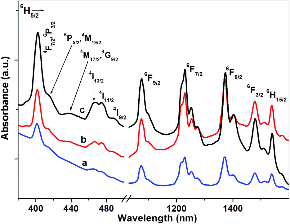
The absorption spectra of some KYF4:Sm3+ samples are presented in Fig. 2. It can be seen that the absorption bands were recorded in the regions of UV-vis (390–520 nm) and NIR (1000–1650 nm). The origin of these bands is given in Carnall's publication.30 In the NIR region, the Sm3+ absorption spectra consist of five bands at wavelengths of 1071, 1228, 1374, 1478 and 1536 nm. These bands correspond to the transitions from the 6H5/2 ground level to the 6F9/2, 6F7/2, 6F5/2, 6F3/2 and 6H15/2 levels, respectively.30 The transitions in the NIR region are allowed by the spin selection rule (ΔS = 0), so they express strong intensities. The 6H5/2 → 6F3/2 transition is a hypersensitive (HS) transition because it obeys the selection rule of ΔS = 0, ΔJ = 1 and ΔL = 1 (the HS transition: ΔS = 0, |ΔJ| ≤ 2 and |ΔL| ≤ 2). It is noted that the energy levels in the UV-vis region of Sm3+ are very close to each other,30 so there is always an overlap of the transitions from the 6H5/2 ground level to the 2S+1LJ levels. For KYF4:Sm3+, the absorption spectra in the UV-vis region show a narrow band at 401 nm (6H5/2 → 6P3/2,4F7/2 transition) and some broad bands centered at around 416, 439, 466, 475 and 489 nm. They are assigned to the 6H5/2 → 6P5/2 + 4M19/2, 6H5/2 → 4M17/2 + 4G9/2, 6H5/2 → 4I13/2,6H5/2 → 4I11/2 and 6H5/2 → 4I9/2 transitions, respectively.30 The absorption transitions in the UV-vis region indicate a weak intensity (except the 6H5/2 → 6P3/2 transition) because they are forbidden by the spin selection rule. The energies of the absorption transitions for Sm3+ in KYF4 (νc) are indicated in Table 1 (see column 3) in comparison with those of free Sm3+ ions (νaqo). It can be seen that there is a shift of some transitions toward high energy when the Sm3+ ions were doped into the KYF4 polycrystalline material. This shift relates to the extension effect of the electron cloud (nephelauxetic effect).5,31 The influence of the nephelauxetic effect is characterized by the bonding parameter (δ). The calculation expressions for the bonding parameter were presented in our previous reports.5,8 The values of δ can provide information about the nature of the RE3+–ligand bond (ionic or covalent bond) in any host. For the KYF4:Sm3+ polycrystalline material, the bonding parameters were found to be −0.745, −0.723, −0.708, −0.672, −0.551 and −0.624 for Sm3+ concentrations of 0.1, 0.5, 1.0, 1.5, 2.0 and 3.0 at%, respectively. The δ parameter gets a negative value for all samples, indicating an ionic feature for the Sm3+–F− bond in KYF4:Sm3+. This bonding nature is the same as that of the Sm3+–F− bond in some crystals such as K2GdF5:Sm3+8 and K2YF5:Sm3+.32
Table 1 Energies (νaqo, νc) and oscillator strengths (fexp, fcal) for some transitions in the Sm3+-doped KYF4 polycrystalline material (KYF4:0.5Sm3+ sample)
|
6H5/2 → |
ν
aqo (cm−1) |
ν
c (cm−1) |
f
exp (×10−6) |
f
cal (×10−6) |
|
6H15/2 |
6508 |
6493 |
0.24 |
0.02 |
|
6F3/2 |
6630 |
6766 |
0.67 |
0.71 |
|
6F5/2 |
7100 |
7294 |
1.77 |
1.58 |
|
6F7/2 |
8000 |
8130 |
2.64 |
3.25 |
|
6F9/2 |
9200 |
9319 |
3.19 |
2.38 |
|
4I9/2 |
20526 |
20534 |
0.26 |
0.45 |
|
4I11/2 |
21100 |
21097 |
0.53 |
0.16 |
|
4I13/2 |
21600 |
21505 |
0.92 |
0.38 |
|
4M17/2, 4G9/2 |
22706 |
22831 |
— |
— |
|
6P5/2, 4M19/2 |
24050 |
24154 |
— |
— |
|
4F7/2, 6P3/2 |
24950 |
24937 |
3.46 |
3.22 |
|
|
δ = −0.723 |
RMS = 0.55 × 10⁻⁷ |
 |
| | Fig. 2 Absorption spectra of the KY1−xF4:xSm3+ samples: (a) x = 0.5 at%, (b) x = 1.5 at% and (c) x = 3.0 at%. | |
It is known that Judd–Ofelt theory is a useful tool for studying the spectroscopy of RE3+ ions doped into any matrix. This theory allows us to not only calculate the optical parameters of the RE3+ ions but also estimate the features of the ligand field. The set of Ωλ (λ = 2, 4, 6) intensity parameters, which are the key of JO theory, can be calculated by using the absorption spectrum. For an electric dipole absorption transition in a RE3+ ion, the oscillator strength (fcal) is calculated by the following formula:18,32
| |  | (1) |
where
Ωλ are the Judd–Ofelt parameters,
n is the refractive index of the material,
J is the total angular momentum of the ground level, and ‖
Uλ‖
2 are the squared doubly reduced matrix elements of the unit tensor operator of rank
λ = 2, 4, 6. The values of ‖
Uλ‖
2 are considered independent from the host and can be found in Carnall's report.
30
From the absorption spectra of the RE3+ ions, the experimental oscillator strength (fexp) is estimated by the expression:18,28
| |  | (2) |
where
α is the molar extinction coefficient at energy
ν (cm
−1).
Using the absorption spectra of the RE3+ ion doped material, the experimental oscillator strength of all transitions can be calculated from eqn (2). The Ω2,4,6 parameters were evaluated by solving the equation system fcal = fexp through the method of least squares. It is noted that the magnitude of Ωλ relates to the kind of RE3+ ions and host matrix, but they do not depend on any particular transition.27 In order to minimize the error, we only use the strong absorption bands for calculating the Ωλ parameters. For the bands having an overlap of transitions, the matrix elements are the sum of the elements for each individual transition. For the KYF4:Sm3+ polycrystalline material, the experimental oscillator strengths of some absorption bands are presented in column 4 of Table 1. The intensity parameters for Sm3+-doped KYF4 were calculated and are indicated in Table 2. The obtained results are compared with those of the Sm3+ ion in some fluoride crystals.8,32–34 It is reported that the Ω2 parameter strongly depends on the characteristics of the local environment around RE3+ ions such as the ligand asymmetry and covalency of the RE3+–ligand bond. A larger value of the Ω2 parameter indicates a higher degree of ligand asymmetry as well as the higher covalency in the RE3+–ligand bond. The data in Table 2 show that the Ω2 magnitude in KYF4:Sm3+ is higher than that in some other fluoride crystals (see Table 2). This result shows that the ligand asymmetry and covalent of the RE3+–ligand bond in the KYF4:Sm3+ polycrystalline material are higher than those in K2GdF5:Sm3+,8 K2YF5:Sm3+,32 BaY2F8:Sm3+,33 and LiYF4:Sm3+34 crystals. Using the Ωλ intensity parameters, the oscillator strength of the absorption transitions was recalculated through eqn (1). The calculated results for the KYF4:0.5Sm3+ sample are presented in column 5 of Table 1. The root mean square (RMS) deviation for this sample was found to be 0.55 × 10⁻⁷. The small value of the RMS deviation shows that there is good agreement between the experimental and calculated results for the KYF4:Sm3+ polycrystalline material.
Table 2 The Ωλ (×10−20 cm2) intensity parameters for Sm3+ in some fluoride crystals
| Materials |
Ω
2
|
Ω
4
|
Ω
6
|
Ref. |
| KYF4:0.1%Sm3+ |
0.85 ± 0.12 |
2.85 ± 0.25 |
3.03 ± 0.34 |
Present |
| KYF4:0.5%Sm3+ |
0.84 ± 0.15 |
3.00 ± 0.31 |
2.68 ± 0.36 |
Present |
| KYF4:1.0%Sm3+ |
0.92 ± 0.12 |
2.81 ± 0.32 |
3.01 ± 0.25 |
Present |
| KYF4:1.5%Sm3+ |
0.95 ± 0.14 |
2.98 ± 0.33 |
3.12 ± 0.28 |
Present |
| KYF4:2.0%Sm3+ |
1.02 ± 0.16 |
3.01 ± 0.29 |
2.78 ± 0.32 |
Present |
| KYF4:3.0%Sm3+ |
0.94 ± 0.13 |
3.02 ± 0.36 |
2.98 ± 0.35 |
Present |
| K2YF5:1.0%Sm3+ |
0.38 |
3.55 |
2.18 |
32
|
| K2GdF5:1.0%Sm3+ |
0.50 |
2.96 |
2.05 |
8
|
| BaY2F8:1.0%Sm3+ |
0.37 |
2.03 |
1.12 |
33
|
| LiYF4:1.0%Sm3+ |
0.55 |
2.44 |
1.72 |
34
|
3.2.2. Excitation and emission spectra and radiative parameters.
The excitation spectra of the Sm3+-doped KYF4 polycrystalline material were measured in the range from 350 nm to 500 nm by monitoring at the emission wavelength of 602 nm (4G5/2 → 6H7/2 transition). As shown in Fig. 3 (curve a), the excitation spectrum exhibits some bands which are generated by the 6H5/2 → 2S+1LJ intra-transitions 4f5 configuration of the Sm3+ ions. Among the excitation transitions, the 6H5/2 → 4F7/2 + 6P3/2 transition centered at 401 nm has the strongest intensity, so it is usually used for luminescence excitation of Sm3+ ions. It can be seen that the excitation bands are in the UV-vis region, which is the activity region of popular sources such as Xe lamps and UV or blue LEDs. This shows an advantage in the application of phosphors doped with Sm3+ ions.
 |
| | Fig. 3 Excitation spectra of Sm3+ (a) and (b) Tb3+ in the KYF4 polycrystalline material. | |
Fig. 4 presents the luminescence spectra of the KYF4:Sm3+ samples under excitation at 401 nm. The luminescence spectra consist of four emission bands at wavelengths of 563, 602, 649 and 711 nm. These bands are attributed to the transitions from the 4G5/2 excited level to the 5H5/2, 5H7/2, 5H9/2 and 5H11/2 ground levels, respectively.30 The 4G5/2 → 5H9/2 and 4G5/2 → 5H11/2 transitions are induced electric dipole transitions, i.e. their intensity may change strongly between various hosts. The 4G5/2 → 5H5/2 and 4G5/2 → 5H7/2 bands include both electric dipole and magnetic dipole transitions. However, the main mechanism of the 4G5/2 → 5H7/2 transition is electric dipole, whereas 4G5/2 → 5H5/2 has a dominant magnetic dipole mechanism.8,16 It can be seen that the 4G5/2 → 5H7/2 transition has the strongest intensity of all. The red-orange characteristic luminescence of Sm3+-doped phosphors under UV excitation is mainly due to this emission band. In fact, the 4G5/2 → 5H7/2 transition may be used for laser action because its branching ratio is usually higher than 50%.8,18 For the KYF4:Sm3+ compressed samples, the experimental branching ratio of the 4G5/2 → 5H7/2 transition is highest among the emission bands and has values larger than 50% for all samples (see column 2 of Table 3). For this reason, some radiative parameters (e.g. stimulated emission cross-sections (σλp, 10−22 cm2), gain bandwidth (σλp × Δλeff, 10−28 cm3) and optical gain (σλp × τcal, 10−25 cm2 s−1)) would be calculated for the 4G5/2 → 5H7/2 transition. The calculation expressions for these parameters were expressed in our previous studies.16,32 The obtained results are presented in Table 3 in comparison with the radiative parameters of some other fluoride crystals.8,32,34 It can be seen that the βexp value for the 4G5/2 → 5H7/2 transition of the KYF4:Sm3+ samples is slightly lower than that of K2YF5:Sm3+ and K2GdF5:Sm3+ but higher than that of LiYF4:Sm3+. The stimulated emission cross-section of the 4G5/2 → 5H7/2 transition in KYF4:Sm3+ is equivalent to that in K2YF5:Sm3+ and K2GdF5:Sm3+.
 |
| | Fig. 4 Emission spectra of the KYF4:Sm3+ samples. | |
Table 3 The radiative parameters of the 4G5/2 → 5H7/2 transition of Sm3+ ions doped in various hosts
| Materials |
β
exp (%) |
σ
λp
|
σ
λp
× Δλeff |
σ
λp
× τcal |
Ref. |
| KYF4:0.1%Sm3+ |
52.3 |
5.71 |
7.04 |
25.0 |
Present |
| KYF4:0.5%Sm3+ |
54.6 |
5.51 |
6.79 |
24.9 |
Present |
| KYF4:1.0%Sm3+ |
53.9 |
5.42 |
6.97 |
23.8 |
Present |
| KYF4:1.5%Sm3+ |
54.6 |
5.98 |
7.31 |
25.2 |
Present |
| KYF4:2.0%Sm3+ |
53.2 |
5.49 |
6.93 |
23.7 |
Present |
| KYF4:3.0%Sm3+ |
54.5 |
5.72 |
7.18 |
24.3 |
Present |
| K2YF5:1.0%Sm3+ |
56.5 |
6.40 |
— |
— |
32
|
| K2GdF5:1.0%Sm3+ |
58.2 |
5.98 |
— |
— |
8
|
| LiYF4:1.0%Sm3+ |
45.8 |
10.39 |
— |
— |
34
|
3.2.3. Evaluating the reliability of JO analysis for the KYF4:Sm3+ polycrystalline material.
As shown in Fig. 4, beside the luminescence bands originating from the 4G5/2 level, the emission spectra of KYF4:Sm3+ also recorded a weak luminescence band in the range from 490 to 545 nm. This band is attributed to the 4F3/2 → 6H5/2 transition in Sm3+ ions.30 The appearance of the 4F3/2 → 6H5/2 luminescence band can be explained as follows. Upon excitation at a 401 nm wavelength, the Sm3+ ions are excited to the 6P3/2 level. Because of the small energy gap between levels from 4F3/2 to 6P3/2, the ions quickly relax to the 4F3/2 level by a multi-phonon process. It is noted that the energy distance from the 4G5/2 level to 4F3/2 is about a few hundred cm−1, which is approximately the energy of two typical phonons in fluoride crystals.5,7,8 Thus, the relaxation rate of ions becomes slower than the previous one. Then, from the 4F3/2 level, the Sm3+ ions can relax to the lower levels in two ways. In the first way, they relax to the ground state by emitting photons and yield the 4F3/2 → 6HJ (J = 5/2, 7/2,…) weak emission bands. However, it is difficult to obtain the 4F3/2 → 6H7/2,9/2 bands because they are overlapped with the 4G5/2 → 6H7/2,9/2 bands. In the second one, the Sm3+ ions drop to the 4G5/2 level through multi-phonon relaxation. In addition, it is known that there is a resonance between the (4F3/2 → 4G5/2) and (6H5/2 → 6H7/2) energy gaps. Thus, the Sm3+ ions can also relax to the 4G5/2 level through the (4F3/2 → 4G5/2) → (6H5/2 → 6H7/2) cross-relaxation channel. On the other hand, because of the small energy gap from the 4G5/2 level to 4F3/2, the electrons in the 4G5/2 level can also be transferred to the 4F3/2 level by the thermal population process.27,29 This process contributes to the luminescence bands originating from the 4F3/2 level. In this case, a three-level model including the 6H5/2 (level 0), 4G5/2 (level 1) and 4F3/2 (level 2) levels can be used to describe the thermalization of the 4F3/2 level. This model is given by the following relation:27,29| |  | (3) |
Here AT(4F3/2) and AT(4G5/2) are the total emission probabilities from the 4F3/2 and 4G5/2 levels, respectively. These parameters, which were calculated using JO theory, have values of 146 and 235 s−1, respectively. I(4F3/2) and I(4G5/2) are the intensities of the 4F3/2 → 6H5/2 and 4G5/2 → 6H15/2 transitions, respectively. k is the Boltzmann constant; kT = 201.6 cm−1 at room temperature. hν1 = 17998 cm−1 and hν2 = 18405 cm−1 are the highest Stark energy of the 4G5/2 → 6H5/2 band and the lowest Stark energy level of the 4F3/2 → 6H5/2 band, respectively. These quantities are found from the emission spectra of Sm3+ ions. g1 = 6 and g2 = 4 are the degeneracies (2J + 1) of the 4G5/2 and 4F3/2 levels, respectively. ΔE = 407 cm−1 is the energy distance from the highest Stark energy of the 4G5/2 → 6H5/2 band to the lowest Stark energy level of the 4F3/2 → 6H5/2 band. Using these parameters, the I(4F3/2)/I(4G5/2) ratio was evaluated to be 0.056. From the experimental luminescence spectrum, the I(4F3/2)/I(4G5/2) ratio was found to be approximately 0.063. It can be seen that the experimental and JO calculated results are in good agreement. The deviation of about 11.1% is within the allowed error area (∼15%) of JO theory. This result indicates that JO theory can be used well for studying the KYF4:Sm3+ polycrystalline samples which were prepared as our study.
3.3. Energy transfer in KYF4:Sm3+
3.3.1. Concentration quenching phenomenon.
As shown in Fig. 4, the luminescence intensity of KYF4:Sm3+ increases with an increase in the concentration of the Sm3+ ions and reaches a maximum value at 1.5 at%, and then decreases. The decrease of the luminescence intensity after a certain concentration is called the concentration quenching phenomenon. It is known that the increase of the Sm3+ concentration leads to the increase of the number of emission centers. The luminescence intensity of Sm3+ ions increases linearly with concentration if there is not energy transfer. In fact, the energy transfer process between Sm3+ always exists in KYF4:Sm3+ (for higher concentrations than 0.5 mol%) and it competes with the radiative process. This means that a part of the excitation energy is released by emitting phonons and the remaining energy is lost due to nonradiative energy transfer. For the dipole–dipole interaction, the energy transfer rate depends on the average distance between ions R as R−6.16,26 The decrease of the ion–ion distance with increasing concentration will cause a strong increase of the energy transfer rate. This will slow down the increase of the luminescence intensity, so the luminescence intensity can only reach a maximum intensity at a certain concentration (e.g. 1.5 mol% for KYF4:Sm3+). After this concentration, the nonradiative process becomes dominant, so the luminescence intensity will decrease rapidly. In KYF4:Sm3+, if the Sm3+ concentration increases beyond 1.5 mol%, the energy transfer rate continues to increase and gradually reaches a saturation value, whereas the luminescence of Sm3+ can be quenched completely.
It is noted that the energy transfer between Sm3+ ions usually relates to the cross relaxation (CR) mechanism.8,16 Some CR channels leading to luminescence quenching of the Sm3+ ions in KYF4 are illustrated in Fig. 5a. After being excited to the 6P3/2 level, Sm3+ ions quickly turn back to the 4G5/2 level by multi-phonon decay, and then they continue to relax to 6HJ (J = 5/2, 7/2, 9/2 and 11/2) by emitting the characteristic radiation. However, increasing the Sm3+ concentration causes a decrease in the ion–ion average distance. This leads to an increase in the interaction between Sm3+ ions. When the interaction is strong enough, the excitation energy can be transferred from an excited ion (at the 4G5/2 level) to a neighbor ion at the ground level (6H5/2). Then, both ions enter the 7FJ (J = 5/2–11/2) energy levels (see Fig. 5a). Finally, the Sm3+ ions relax to the ground level through multi-phonon decay. Thus, the luminescence of the 4G5/2 level ions would be quenched.
 |
| | Fig. 5 (a) The CR channels between Sm3+ ions; and (b) the emission process of Tb3+ ions and the energy transfer from Tb3+ ions to Sm3+. | |
3.3.2. Decay curve analysis.
The decay curves of the 4G5/2 level in the KYF4:Sm3+ samples were observed at an emission wavelength of 602 nm under excitation at 401 nm. The results are exhibited in Fig. 6. At a low concentration of the Sm3+ dopant (0.1 mol%), the decay curve, which is mono-exponential, is fitted to a single exponential, I(t) = I0exp(−t/τ). When the energy transfer process becomes significant at high concentration, the decay curves are not mono-exponential. The experimental lifetime is determined by the formula:8,16| |  | (4) |
 |
| | Fig. 6 Decay curves of some KYF4:xSm3+ samples: (a) x = 0.1 at%, (b) x = 0.5 at%, (c) x = 1.5 at% and (d) x = 3.0 at%. | |
For the KYF4:Sm3+ samples, the experimental lifetime (τexp) of the 4G5/2 level was found to be 4.34, 3.72, 3.12, 2.54, 2.19 and 1.85 ms for Sm3+ concentrations of 0.1, 0.5, 1.0, 1.5, 2.0 and 3.0 at%, respectively. The experimental lifetime decreases with the increase of the Sm3+ concentration. The quenching of the lifetime is also assigned to the CR process between Sm3+ ions.8 Using JO theory, the calculated lifetime (τcal) was estimated to be 4.38, 4.44, 4.38, 4.21, 4.31 and 4.28 ms for Sm3+ concentrations of 0.1, 0.5, 1.0, 1.5, 2.0 and 3.0 at%, respectively. It can be seen that the experimental lifetime is always smaller than the calculated lifetime because the nonradiative processes have been ignored in JO analysis. The quantum efficiency of a material is defined as the ratio of the experimental lifetime to the calculated lifetime: η = τexp/τcal.16,32 The energy transfer rate (WET) was estimated by using the following formula:27,32
| |  | (5) |
For KYF4:Sm3+, the calculated results for η and WET are presented in Table 4. It can be seen that the quantum efficiency and energy transfer rate decrease with an increase of the concentration of Sm3+ ions.
Table 4 Energy transfer parameters between Sm3+ ions in the KYF4:Sm3+ material
|
C (Sm3+) |
η (%) |
W
ET (s−1) |
Q
|
C
DA (cm6 s−1) |
R
0 (Å) |
| 0.1 |
— |
— |
— |
— |
— |
| 0.5 |
83.78 |
43.59 |
0.136 |
4.06 × 10−41 |
7.49 |
| 1.0 |
71.23 |
92.21 |
0.315 |
5.45 × 10−41 |
7.86 |
| 1.5 |
60.33 |
156.17 |
0.512 |
6.40 × 10−41 |
8.08 |
| 2.0 |
50.81 |
224.60 |
0.695 |
6.63 × 10−41 |
8.13 |
| 3.0 |
43.22 |
306.89 |
1.017 |
6.32 × 10−41 |
8.06 |
As shown in Fig. 6, the decay curve is a single exponential at low concentration (0.1 at%) because the energy transfer process is negligible at this concentration. However, the decay curves are no longer single exponentials because of the appearance of the energy transfer process between the ions at higher concentrations.16,19 Information about the interaction mechanism and energy transfer parameters can be found by analyzing the decay curves through the Inokuti–Hirayama (IH) model.26 According to the IH model, when only taking into account energy transfer via CR, the decay curves are given by the equation:27,35
| |  | (6) |
where
t is the time after excitation;
I and
I0 are the luminescence intensities at time
t and
t0 = 0, respectively;
τ0 is the intrinsic lifetime of the donor;
Q is the energy transfer parameter; and
S is a parameter depending on the kind of interaction between ions.
S can take values of 6, 8 or 10 for interactions of dipole–dipole (DD), dipole–quadrupole (DQ) or quadrupole–quadrupole (QQ), respectively.
For the KYF4:xSm3+ (x = 0.5–3.0 at%) samples, the decay curves of the 4G5/2 level were fitted to eqn (6), in which the τ0 value is the lifetime of the KYF4:0.1%Sm3+ sample (4.34 ms). The results are indicated in Fig. 6, where the red lines are the fitting lines for samples with S = 6 and the blue dashed lines are the fitting lines for the KYF4:3.0%Sm3+ sample with S = 8 and 10. It can be seen that the decay curves of all samples are fitted the best with S = 6. This result indicates that the DD interaction mechanism plays a dominant role in the energy transfer process between Sm3+ ions. The main interaction mechanism depends on the local environment around the RE3+ ions. For Sm3+ ions, the DD interaction mechanism was also recorded in some materials such as the LiYF4:Sm3+ crystal,35 zinc potassium fluorophosphates glass,36 telluroborate16 glasses and lead fluoroborate,37 whereas a DQ dominant interaction mechanism was found in the K2GdF5:Sm3+ single crystal.8 The Q energy transfer parameter was also found by fitting the decay curves and is shown in Table 4. From the Q values, the microinteraction parameter (CDA) and the critical distance (R0) for the Sm3+–Sm3+ energy transfer process were calculated by using the formulas in our previous reports.8,16 The obtained results are indicated in Table 4.
Yamaga reported that the reason for the quenching of the luminescence and lifetime of the Sm3+:4G5/2 level is the nonradiative energy transfer process between ions in each Sm3+–Sm3+ pair.35 In KYF4:Sm3+, the Sm3+ ions substitute for Y3+ ions and a Sm3+ ion at the origin (a Y3+ site) has high potential to form a pair with a neighbor Sm3+ ion at the first, second or third shortest distances in the crystal lattice.35 The probability of pair formation depends on the separation distance between the ions. Because the radius of the Sm3+ ion is larger than that of the Y3+ ion, the increase of the Sm3+ concentration in KYF4 causes a decrease in the separation distance between the Sm3+ ions, having a large pair formation probability.35 This behavior increases the probability of Sm3+–Sm3+ pair formation, leading to the enhancement of the nonradiative energy transfer between the Sm3+ ions. This result is expressed by the increase of the WET, Q and CDA parameters (see Table 4). Additionally, for high concentrations of Sm3+ ions, the crystal field of an ion (e.g. ion A) is perturbed by other ions, in which each ion generates an axial distortion or strain toward ion A.35 This modifies the energy levels and creates an electric dipole moment into the f–f forbidden transitions of the Sm3+ ion, leading to line-broadening and shortening of the lifetime of the Sm3+ excitation level.
3.4. Energy transfer in the KYF4:Tb3+,Sm3+ polycrystalline material
Energy transfer from a donor ion to an acceptor ion often leads to the fluorescence quenching of materials if these ions have the same feature (e.g. Sm3+–Sm3+ or Dy3+–Dy3+ ions).16,35 However, the energy transfer process between ions with different features (e.g. Tb3+ and Sm3+) can yield an enhancement of the luminescence of the acceptor center.1,3,17 In this section, the luminescence enhancement of the Sm3+ ions in KYF4:Tb3+,Sm3+ through the energy transfer process from Tb3+ to Sm3+ ions will be discussed in detail.
Curve b in Fig. 3 shows the excitation spectrum of Tb3+ ion singly doped KYF4. This spectrum was recorded by monitoring at an emission wavelength of 543 nm corresponding to the 5D4 → 7F5 transition. There are three excitation bands which are observed in the range from 360 to 500 nm. These bands are assigned to the 7F6 → 5G6 (373 nm), 7F6 → 5D3 (377 nm) and 7F6 → 5D4 (484 nm) intra-transitions 4f8 configuration of the Tb3+ ions.22 It can be seen that the excitation band centered at 373 nm was observed in the excitation spectra of both Tb3+ and Sm3+ ions. Thus, the luminescence of both the Tb3+ and Sm3+ ions can be obtained simultaneously with this excitation wavelength. Fig. 7 exhibits the emission spectra of the KYF4:Tb3+ and KYF4:Tb3+,Sm3+ samples under excitation at 373 nm. For KYF4:Tb3+, the emission includes some bands centered at 413, 434, 455, 467, 484, 542, 581 and 621 nm. These are characteristic emission bands of Tb3+ ions. They are attributed to the 5D3 → 7F5, 5D3 → 7F4, 5D3 → 7F3, 5D3 → 7F2, 5D4 → 7F6, 5D4 → 7F5, 5D4 → 7F4 and 5D4 → 7F3 transitions, respectively.22 For the KYF4:Tb3+,Sm3+ samples, beside the Tb3+ emission bands, the luminescence spectra also show some characteristic emission bands of Sm3+ ions at 563 nm (4G5/2 → 6H5/2), 602 nm (4G5/2 → 6H5/2) and 449 nm (4G5/2 → 6H5/2).
 |
| | Fig. 7 Emission spectra of the KYF4:1%Tb3+,xSm3+ samples (x = 0, 1.0, 2.0 and 3.0 at%) upon excitation at 373 nm. | |
In order to estimate the application potential of the KYF4:Tb3+,Sm3+ polycrystalline material for light-emitting diodes, the Commission Internationale de L’Eclairage (CIE) chromaticity coordinates were calculated by using the emission under excitation at 373 nm. The obtained results are indicated in Table 5 and Fig. 8. The correlated color temperature (CCT) is often used to interpret the luminescence properties of a light source.38 The CCT is the temperature of a black body whose color tone most closely resembles that of a light source.1 This parameter is estimated by using the following formula:27,38
| | | CCT = –449n3 + 3525n2 − 6823n + 5520.33 | (7) |
where
n = (
x −
xe)/(
y −
ye) and (
xe = 0.332,
ye = 0.186).
Table 5 The color coordinates (x, y) and correlated color temperature of KYF4:Tb3+,Sm3+
|
C (Sm3+) (at%) |
x
|
y
|
CCT (K) |
| 0 |
0.247 |
0.422 |
8455 |
| 0.5 |
0.271 |
0.408 |
7670 |
| 1.0 |
0.328 |
0.372 |
5669 |
| 2.0 |
0.371 |
0.356 |
4135 |
| 3.0 |
0.352 |
0.361 |
4785 |
 |
| | Fig. 8 CIE chromaticity coordinate diagram of KYF4:1.0%Tb3+,xSm3+ under excitation at 373 nm. | |
The calculated data for the chromaticity coordinates show that the luminescence of the samples doped with 1.0 and 3 at% Sm3+ ions is near the white light region. For Sm3+ concentrations of 0 and 0.5 at%, the CCTs are higher than 6000 K, i.e. the color feature of these samples is in the cool light region, whereas the CCT value of the KYF4:1.0%Tb3+,1.0%Sm3+ and KYF4:1.0%Tb3+,3.0%Sm3+ samples is in the neutral white light region with the vision of humans.
As shown in the emission spectra of KYF4:Tb3+,Sm3+ (see Fig. 6), the emission intensity of Tb3+ decreases strongly with an increase in the Sm3+ concentration. This shows the existence of energy transfer from Tb3+ ions to Sm3+. The emission spectra also show that the emission intensity of Sm3+ ions increases firstly and reaches a maximum intensity at a concentration in the range from 1.0 to 2.0 at%, and then decreases. The decrease of the Sm3+ luminescence intensity after this concentration results from concentration quenching, which is due to the cross relaxation between Sm3+ ions. The CR channels have been shown in Fig. 5a. The energy transfer from Tb3+ ions to Sm3+ can be illustrated as the energy diagram in Fig. 5b. After being excited to the 5G6 level, the Tb3+ ions relax non-radiatively to the 5D3 level. From this level, the Tb3+ ions can return to the ground state through two ways. In the first way, the Tb3+ ions relax to 7FJ=0–6 by emitting luminescence in the range from 413 to 467 nm. In the second one, the Tb3+ ions relax to the 5D4 level through emitting multi-phonon or infrared radiation or [5D3 → 5D4] → [7F6 → 7F0] cross relaxation (see Fig. 5b). However, until now, infrared radiation yielded from the 5D3 → 5D4 transition has not been observed in any material yet. The Tb3+ ions then continue to relax to the 7FJ=0–6 level and generate emission bands in the region of 484–621 nm. Nevertheless, the 5D3 and 5D4 levels in Tb3+ ions are very close to the 4G11/2 and 4G7/2 levels of Sm3+ ions, respectively. Thus, a part of the excited energy can be transferred from the Tb3+ ions to Sm3+ (see Fig. 5b). This process leads to the luminescence enhancement of Sm3+ and the luminescence quenching of Tb3+ ions.
Energy transfer also causes lifetime quenching of the Tb3+ excited levels (e.g. the 5D4 level). This is confirmed through the decay curves of the Tb3+:5D4 level, which are shown in the inset of Fig. 6. In order to the get these curves, the emission wavelength was fixed at 542 nm (5D4 → 7F5 transition) under excitation at 373 nm. For the KYF4:1.0%Tb3+ sample, the decay curve is a single exponential with a lifetime of 4.67 ms. This experimental lifetime is typical for the Tb3+:5D4 level in some fluoride crystals such as KGdF4:Tb3+,10 K2YF5:Tb3+,5 and K2GdF5:Tb3+.39 For the KYF4:Tb3+,Sm3+ samples, the decay curves become non-exponential and the luminescence intensity decreases faster than that of the KYF4:Tb3+ sample. The lifetimes were found to be 3.82, 3.28, 2.45 and 1.97 ms for Sm3+ concentrations of 0.5, 1.0, 2.0 and 3.0 at%, respectively. The energy transfer efficiency (ηET) from Tb3+ to Sm3+ is calculated by the following formula:23,40
| |  | (8) |
where
τ(Tb) and
τ(Tb,Sm) are the lifetimes of the Tb
3+:
5D
4 level in the KYF
4:Tb
3+ and KYF
4:Tb
3+,Sm
3+ samples, respectively. The values of
ηET were estimated to be 18.2, 29.8, 47.5 and 58.9% for Sm
3+ concentrations of 0.5, 1.0, 2.0 and 3.0 at%, respectively. It is known that the interaction between ions depends on their average distance: the shorter the distance, the stronger the interaction. The increase of the Sm
3+ concentration in KYF
4:Tb
3+,Sm
3+ results in the decrease of the Tb
3+–Sm
3+ average distance. The reduction of the ion–ion separation distance creates an increase in the interaction between them, leading to an increase in the Tb
3+–Sm
3+ ion formation.
35 This is the main reason for the increase of the rate and efficiency of the energy transfer process from Tb
3+ ions to Sm
3+. The critical distance (
Rc) of the energy process is the Tb
3+–Sm
3+ average distance, at which the radiative probability of the Tb
3+ ion equals the energy transfer rate from the Tb
3+ ion to Sm
3+. In other words, the energy transfer efficiency is 50% at this distance. For the crystals, the
Rc value can be estimated by Blasse's formula:
41,42| |  | (9) |
where
V is the volume of a unit cell of the crystal matrix;
N is the number of host cations in a unit cell; and
Cx is the total concentration of Tb
3+ and Sm
3+ ions when
ηET = 0.5. For KYF
4:Tb
3+,Sm
3+, the
V and
N parameters, which are found from the JCPDS No. 027-0466 standard card, are 1709.73 Å
3 and 18, respectively. From the dependence of
ηET on the Sm
3+ concentration, the value of
Cx was found to be approximately 3.2 at%. Thus, the critical distance for KYF
4:1%Tb
3+,Sm
3+ is estimated to be 17.83 Å. In general, energy transfer from a donor to an acceptor may occur through exchange interaction or electric multipolar interaction.
10,42 However, the exchange interaction only appears at ion–ion distances which are less than 5 Å.
17,23,41 For KYF
4:1.0%Tb
3+,Sm
3+, the Tb
3+–Sm
3+ critical distance of 17.83 Å is too large for the exchange interaction to take place,
i.e. the Tb
3+–Sm
3+ interaction happens
via the multipolar interaction. Using the IH model as in our previous reports,
17,39 the decay curves of the Tb
3+:
5D
4 level were fitted the best with
S = 6 (see the inset of
Fig. 6). This result implies that the energy transfer from Tb
3+ ions to Sm
3+ takes place
via a main mechanism of the DD interaction. This interaction seems to be typical for the Tb
3+–Sm
3+ pair because it is found in many crystals such as K
2YF
5:Tb
3+,Sm
3+,
39 K
2GdF
5:Tb
3+,Sm
3+,
39 BaGdF
5:Tb
3+,Sm
3+,
23 NaGdF
4:Tb
3+,Sm
3+,
9 KGdF
4:Tb
3+,Sm
3+,
17 Ba
3La(PO
4):Tb
3+,Sm
3+,
43 Y
3Al
2Ga
3O
12:Tb
3+,Sm
3+,
44 and Na
3Bi(PO
4)
245 as well as some glasses as telluroborate
17 and zinc phosphate barium titanate.
46
4. Conclusion
A three-level model has shown that Judd–Ofelt analysis can be applied well for the KYF4:Sm3+ polycrystalline material. The large values of the experimental branching ratio and stimulated emission cross-sections for the 4G5/2 → 5H7/2 transition indicate high application potential for KYF4:Sm3+ in the optical amplifier area. For the KYF4:Sm3+ material, the luminescence quenching relates to cross relaxation between Sm3+. The DD interaction is the dominant mechanism in this process. In KYF4Tb3+,Sm3+, the Tb3+ ion plays role as a sensitizer center for the luminescence of Sm3+ ions under excitation at 373 nm. For this excitation condition, the color tone of KYF4:1%Tb3+,xSm3+ is near white at 2.0 and 3.0 at% Sm3+ concentrations. The energy transfer from Tb3+ ions to Sm3+ in KYF4:1%Tb3+,xSm3+ takes place through the DD interaction mechanism with a critical distance of 17.83 Å. The energy transfer efficiency (ηET) from Tb3+ to Sm3+ increases from 18.2 to 58.9% when the Sm3+ concentration increases from 0.5 to 3.0 at%.
Conflicts of interest
There are no conflicts to declare.
References
- S. Ye, F. Xiao, Y. X. Pan, Y. Y. Ma and Q. Y. Zhang, Phosphors in phosphor-converted white light-emitting diodes: recent advances in materials, techniques and properties, Mater. Sci. Eng., R, 2010, 71, 1–34 CrossRef.
- N. T. Hien, Y. Y. Yu, K. C. Park, N. X. Ca, T. T. K. Chi, B. T. T. Hien, L. D. Thanh, P. V. Do, P. M. Tan and P. T. T. Ha, Influence of Eu doping on the structural and optical properties of Zn1−xEuxSe quantum dots, J. Phys. Chem. Solids, 2021, 148, 109729 CrossRef CAS.
- G. B. Santos, B. G. Hernandez, I. R. Martin, L. G. Lemus and J. Sanchiz, Visible and NIR emitting Yb(III) and Er(III) complexes sensitized by β-diketonates and phenanthroline derivatives, RSC Adv., 2020, 10, 27815–27823 RSC.
- H. Boubekri, M. Diaf, K. Labbaci, L. Guerbous, T. Duvaut and J. P. Jouart, Synthesis and optical properties of Tb3+ doped CdF2 single crystals, J. Alloys Compd., 2013, 575, 339–343 CrossRef CAS.
- V. P. Tuyen, V. X. Quang, N. M. Khaidukov, L. D. Thanh, N. X. Ca, N. V. Hao, N. V. Nghia and P. V. Do, K2YF5:Tb3+ single crystal: an in-depth study of spectroscopic properties, energy transfer and quantum cutting, Opt. Mater., 2020, 106, 109939 CrossRef CAS.
- P. Rawat, S. K. Saroj, J. Kaur and R. Nagarajan, Luminescent properties of K2SbF5:Ln (Ln = Eu3+, Tb3+, Er3+) obtained by a facile room temperature mechanochemical synthesis, J. Lumin., 2019, 210, 392–396 CrossRef CAS.
- M. A. Gusowski, A. Gągor, M. T. Gusowska and W. R. Romanowski, Crystal structure and vibrational properties of new luminescent hosts K3YF6 and K3GdF6, J. Solid State Chem., 2006, 179, 3145–3150 CrossRef CAS.
- P. V. Do, V. P. Tuyen, V. X. Quang, N. M. Khaidukov, N. T. Thanh, B. Sengthong and B. T. Huy, Energy transfer phenomena and Judd-Ofelt analysis on Sm3+ ions in K2GdF5 crystal, J. Lumin., 2016, 179, 93–99 CrossRef CAS.
- H. Guan, G. Liu, J. Wang, X. Dong and W. Yu, Multicolor tunable luminescence and paramagnetic properties of NaGdF4:Tb3+/Sm3+ multifunctional nanomaterials, Dalton Trans., 2014, 43, 10801–10808 RSC.
- P. V. Do, V. X. Quang, L. D. Thanh, V. P. Tuyen, N. X. Ca, V. X. Hoa and H. V. Tuyen, Energy transfer and white light emission of KGdF4 polycrystalline co-doped with Tb3+/Sm3+ ions, Opt. Mater., 2019, 92, 174–180 CrossRef.
- M. Karbowiak, A. Mech, L. Kepinski, W. Mielcarek and S. Hubert, Effect of crystallite size on structural and luminescent properties of nanostructured Eu3+:KGdF4 synthesised by co-precipitation method, J. Alloys Compd., 2005, 400, 67–75 CrossRef CAS.
- P. M. Tan, N. X. Ca, N. T. Hien, H. T. Van, P. V. Do, L. D. Thanh, V. H. Yen, V. P. Tuyen and P. T. Tho, New insights on the energy transfer mechanisms of Eu-doped CdS quantum dots, Phys. Chem. Chem. Phys., 2020, 22, 6266 RSC.
- S. Zheng, W. Chen, D. Tan, J. Zhou, Q. Guo, W. Jiang, C. Xu, X. Liu and J. Qiu, Lanthanide-doped NaGdF4 core-shell nanoparticles for non-contact self-referencing temperature sensors, Nanoscale, 2014, 6, 5675–5679 RSC.
- N. T. Hien, N. X. Ca, N. T. Kien, N. T. Luyen, P. V. Do, L. D. Thanh, H. T. Van, S. Bharti, Y. Wang, N. T. M. Thuy and P. M. Tan, Structural, optical properties, energy transfer mechanism and quantum cutting of Tb3+ doped ZnS quantum dots, J. Phys. Chem. Solids, 2020, 147, 109638 CrossRef CAS.
- R. T. Wegh, H. Donker, K. D. Oskam and A. Meijerink, Visible quantum cutting in LiGdF4:Eu3+ through downconversion, Science, 1999, 283, 663–669 CrossRef CAS.
- P. V. Do, V. P. Tuyen, V. X. Quang, L. X. Hung, L. D. Thanh, T. Ngoc, N. V. Tam and B. T. Huy, Investigation of spectroscopy and the dual energy transfer mechanisms of Sm3+-doped telluroborate glasses, Opt. Mater., 2016, 55, 62–67 CrossRef.
- V. Uma, M. Vijayakumar, K. Marimuthu and G. Muralidharan, Luminescence and energy transfer studies on Sm3+/Tb3+ co-doped telluroborate glasses for WLED applications, J. Mol. Struct., 2018, 1151, 266–276 CrossRef CAS.
- K. S. Rudramamba, D. V. K. Reddy, T. S. Rao, S. K. Taherunnisa, N. Veeraiah and M. R. Reddy, Optical properties of Sm3+ doped strontium bismuth borosilicate glasses for laser applications, Opt. Mater., 2019, 89, 68–79 CrossRef CAS.
- V. X. Quang, P. V. Do, N. X. Ca, L. D. Thanh, V. P. Tuyen, P. M. Tan, V. X. Hoa and N. T. Hien, Role of modifier ion radius in luminescence enhancement from 5D4 level of Tb3+ ion doped alkali-alumino-telluroborate glasses, J. Lumin., 2020, 221, 117039 CrossRef CAS.
- S. N. C. Santos, K. T. Paula, J. M. P. Almeida, A. C. Hernandes and C. R. Mendonça, Effect of Tb3+/Yb3+ in the nonlinear refractive spectrum of CaLiBO glasses, J. Non-Cryst. Solids, 2019, 524, 119637 CrossRef CAS.
- T. O. Sales, R. J. Amjad, C. Jacinto and M. R. Dousti, Concentration dependent luminescence and cross-relaxation energy transfers in Tb3+ doped fluoroborate glasses, J. Lumin., 2019, 205, 282–286 CrossRef CAS.
- W. T. Carnall, P. R. Fields and K. Rajnak, Electronic energy levels in the trivalent lanthanide aquo ions. III. Tb3+, J. Chem. Phys., 1968, 49, 4447–4449 CrossRef CAS.
- H. Guan, Y. Sheng, Y. Song, K. Zheng, C. Xu, X. Xie, Y. Dai and H. Zou, White lightemitting, tunable color luminescence, energy transfer and paramagnetic properties of terbium and samarium doped BaGdF5 multifunctional nanomaterials, RSC Adv., 2016, 6, 73160–73169 RSC.
- B. R. Judd, Phys. Optical Absorption intensities of rare earth ions, Phys. Rev., 1962, 127, 750–761 CrossRef CAS.
- G. S. Ofelt, Intensities of crystal spectra of rare earth ions, J. Chem. Phys., 1962, 37, 511–520 CrossRef CAS.
- M. Inokuti and F. Hirayama, Influence of energy transfer by the exchange mechanism on donor luminescence, J. Chem. Phys., 1965, 43, 1978–1989 CrossRef CAS.
- V. P. Tuyen, V. X. Quang, P. V. Do, L. D. Thanh, N. X. Ca, V. X. Hoa, L. V. Tuat, L. A. Thi and M. Nogami, An in-depth study of the Judd-Ofelt analysis, spectroscopic properties and energy transfer of Dy3+ in alumino-lithium-telluroborateglasses, J. Lumin., 2019, 210, 435–443 CrossRef CAS.
- M. G. Brika, T. Ishii, A. M. Tkachuk, S. E. Ivanova and I. K. Razumova, Calculations of the transitions intensities in the optical spectra of Dy3+:LiYF4, J. Alloys Compd., 2004, 374, 63–68 CrossRef.
- M. D. Shinn, W. A. Sibley, M. G. Drexhage and R. N. Brown, Optical transitions of Er3+ ions in fluorozirconate glass, Phys. Rev. B: Condens. Matter Mater. Phys., 1983, 27, 6635 CrossRef CAS.
- W. T. Carnall, P. R. Fields and K. Rajnak, Electronic energy levels of trivalent lanthanide aquo ions. I. Prz3+, Nd3+, Pm3+, Sm3+, Dy3+, Ho3+, Er3+, and Tm3+, J. Chem. Phys., 1968, 49, 4424 CrossRef CAS.
- K. Binnemans, Interpretation of europium(III) spectra, Coord. Chem. Rev., 2015, 295, 1–45 CrossRef CAS.
- P. V. Do, V. P. Tuyen, V. X. Quang, N. T. Thanh, V. T. T. Ha, N. M. Khaidukov, Y. I. Lee and B. T. Huy, Judd–Ofelt analysis of spectroscopic properties of Sm3+ ions in K2YF5 crystal, J. Alloys Compd., 2012, 520, 262–265 CrossRef.
- D. P. Thomas, Spectroscopic properties and Judd-Ofelt analysis of BaY2F8:Sm3+, J. Opt. Soc. Am. B, 2014, 31, 1777–1789 CrossRef.
- G. Q. Wang, Y. F. Lin, X. H. Gong, Y. J. Chen, J. H. Huang, Z. D. Luo and Y. D. Huang, Polarized spectral properties of Sm3+:LiYF4 crystal, J. Lumin., 2014, 147, 23–26 CrossRef CAS.
- M. Yamaga, H. Uno, S. I. Tsuda, J. P. R. Wells and T. P. J. Han, Resonant energy transfer and cross relaxation between Sm3+ ions in LiYF4 crystals, J. Lumin., 2012, 132, 1608–1617 CrossRef CAS.
- S. Thomas, R. George, S. Nayab Rasool, M. Rathaiah, V. Venkatramu, C. Joseph and N. V. Unnikrishnan, Optical properties of Sm3+ ions in zinc potassium fluorophosphate glasses, Opt. Mater., 2013, 36, 242–250 CrossRef CAS.
- S. Arunkumar and K. Marimuthu, Concentration effect of Sm3+ ions in B2O3–PbO–PbF2–Bi2O3–ZnO glasses – structural and luminescence investigations, J. Alloys Compd., 2013, 565, 104–114 CrossRef CAS.
- C. S. McCamy, Correlated color temperature as an explicit function of chromaticity coordinates, Color Res. Appl., 1992, 17, 142–144 CrossRef.
- P. V. Do, V. P. Tuyen, V. X. Quang, L. D. Thanh, N. M. Khaidukov, V. N. Makhov and N. T. Thanh, Sensitization of luminescence from Sm3+ ions in fluoride hosts K2YF5 and K2GdF5 by doping with Tb3+ ions, J. Lumin., 2019, 209, 340–345 CrossRef CAS.
- S. Marchesi, C. Bisio and F. Carniato, Novel light-emitting clays with structural Tb3+ and Eu3+ for chromate anion detection, RSC Adv., 2020, 10, 29765–29771 RSC.
- C. K. Chang and T. M. Chen, Sr3B2O6:Ce3+,Eu2+: a potential single-phased white-emitting borate phosphor for ultraviolet light-emitting diodes, Appl. Phys. Lett., 2007, 91, 081902 CrossRef.
- Z. Xia and R. S. Liu, Unable blue-green color emission and energy transfer of Ca2Al3O6F:Ce3+,Tb3+ phosphors for near-UV white LEDs, J. Phys. Chem. C, 2012, 116, 15604–15609 CrossRef CAS.
- W. Zhou, M. Gu, Y. Ou, C. Zhang, X. Zhang, L. Zhou and H. Liang, Concentration-driven selectivity of energy transfer channels and color tunability in Ba3La(PO4)3:Tb3+,Sm3+ for warm white LEDs, Inorg. Chem., 2017, 56, 7433–7442 CrossRef CAS.
- Z. Li, B. Zhong, Y. Cao, S. Zhang, Y. Lv, Z. Mu, Z. Hu and Y. Hu, Energy transfer and luminescence properties of Y3Al2Ga3O12:Tb3+,Sm3+ as a multi-colour emitting phosphors, J. Mater. Sci.: Mater. Electron., 2019, 30, 10491–10498 CrossRef CAS.
- Z. Zhu, G. Fu, Y. Yang and Y. Yang, Energy transfer, tunable luminescence, and thermal stability of Tb3+–Sm3+-codoped Na3Bi(PO4)2 phosphors, J. Mater. Sci., 2016, 51, 6944–6954 CrossRef CAS.
- K. Jha, A. K. Vishwakarma, M. Jayasimhadri and D. Haranath, Multicolor and white light emitting Tb3+/Sm3+ co-doped zinc phosphate barium titanate glasses via energy transfer for optoelectronic device applications, J. Alloys Compd., 2017, 719, 116–124 CrossRef CAS.
|
| This journal is © the Owner Societies 2020 |
Click here to see how this site uses Cookies. View our privacy policy here. 
 b,
Luong Duy
Thanh
a,
Nguyen
Van Nghia
a and
Tran Thi Chung
Thuy
a
b,
Luong Duy
Thanh
a,
Nguyen
Van Nghia
a and
Tran Thi Chung
Thuy
a