
 Open Access Article
 This Open Access Article is licensed under a
 Creative Commons Attribution 3.0 Unported Licence
Quantifying how step-wise fluorination tunes local solute hydrophobicity, hydration shell thermodynamics and the quantum mechanical contributions of solute–water interactions†
João R.
Robalo‡
 a,
Denilson
Mendes de Oliveira‡
b,
Petra
Imhof§
c,
Dor
Ben-Amotz
b and
Ana
Vila Verde¶
*a
a,
Denilson
Mendes de Oliveira‡
b,
Petra
Imhof§
c,
Dor
Ben-Amotz
b and
Ana
Vila Verde¶
*a
aDepartment of Theory & Bio-Systems, Max Planck Institute for Colloids and Interfaces, Science Park, Potsdam 14476, Germany. E-mail: ana.vilaverde@mpikg.mpg.de
bPurdue University, Department of Chemistry, West Lafayette, IN 47907, USA
cInstitute for Theoretical Physics, Free University of Berlin, Arnimallee 14, 14195 Berlin, Germany
First published on 29th September 2020
Abstract
The ability to locally tune solute–water interactions and thus control the hydrophilic/hydrophobic character of a solute is key to control molecular self-assembly and to develop new drugs and biocatalysts; it has been a holy grail in synthetic chemistry and biology. To date, the connection between (i) the hydrophobicity of a functional group; (ii) the local structure and thermodynamics of its hydration shell; and (iii) the relative influence of van der Waals (dispersion) and electrostatic interactions on hydration remains unclear. We investigate this connection using spectroscopic, classical simulation and ab initio methods by following the transition from hydrophile to hydrophobe induced by the step-wise fluorination of methyl groups. Along the transition, we find that water–solute hydrogen bonds are progressively transformed into dangling hydroxy groups. Each structure has a distinct thermodynamic, spectroscopic and quantum-mechanical signature connected to the associated local solute hydrophobicity and correlating with the relative contribution of electrostatics and dispersion to the solute–water interactions.
Introduction
Cellular machinery, structural scaffolds, and compartments are essentially composed of sugars, amino acids, nucleobases and lipids whose functional groups, to put it simply, either form hydrogen bonds with each other and with water, or segregate from water. The balance of formed, perturbed and broken hydrogen bonds in the hydration shell – the balance of hydrophilic and hydrophobic interactions – influences self assembly, structure and functionality:1–7 life itself.Tuning hydrophobicity by manipulating hydrogen bonds has been a longstanding goal and challenge in materials science,8–13 organic chemistry14–16 and supramolecular chemistry.17–20 However, the usual strategies employed to modify hydrogen bond patterns (the simplest being methylation and hydroxylation) also result in changes in molecular surface area and topology, meaning that water–solute and water–water hydrogen bonds are simultaneously affected. The challenge in such strategies is often perceived as the prediction of which hydrogen bonds are broken, formed or perturbed, and how they will change a solute's hydrophobicity. We propose that this formulation is insufficient in that, at its essence, the challenge is also conceptual—to determine what is a hydrogen bond, what does it mean to perturb one in the context of a hydration shell, and what is its connection with local hydrophobicity. A hydration shell contains a distribution of hydrogen bond energies arising from mutual interactions of many water molecules and the solute that are, in turn, influenced by interactions with even more molecules. Importantly, the entropic contribution to hydrogen bond stability—a key factor in the theory of the hydrophobic effect—cannot be recovered from gas phase measurements. Here we address the above questions using direct measurements of hydration shell spectra, and calculations to enable the discretization of hydration shell structures, of systems with a set of chemical modifications resulting in stepwise changes in hydrophobicity—enter fluorine.
The consecutive fluorination of a methyl group yields both a hydrophile (monofluoromethyl) and a hydrophobe (trifluoromethyl) only two H-to-F substitutions apart.21 The associated minimal changes to molecular surface area and the retention of molecular topology result in a minimal volume-induced structural perturbation of the hydration water molecules.21 Furthermore, classical calculations suggest that changes in the hydrophobicity of fluoromethyl groups along this series are mainly enthalpic.21 Interestingly, while mostly absent from biological systems, fluorine's forays into synthetic biology result in a remarkable ability to manipulate cellular machinery,22–25 structural motifs26–28 and compartments.29,30 In chemistry, fluorination is routinely used as a provider of curious and useful characteristics, from the ability to form hydrogen bond donor carbon atoms31–34 to the unusual properties of perfluorinated oils.35–37
We combined experimental Raman multivariate curve resolution (Raman-MCR) spectroscopy, simulations using both classical force fields and density functional theory potentials, and quantum-mechanical calculations to quantify the changes in the hydrophobicity of a series of fluorinated solutes, the thermodynamics of putative hydrogen bonds in their hydration shells and the first principle contributions to water–solute interactions and hydration thermodynamics. Our chosen series of solutes is the simplest, most gradual, experimentally-accessible hydrophilic-to-hydrophobic transition: 2-mono-, 2,2-di-, and 2,2,2-trifluoroethanol (MFE, DFE and TFE, respectively). We find that the hydration shell of each fluoromethyl group contains structures consisting of water hydroxy groups that point to the solute. We term these structures “hydrogen bond-like” because they obey typical geometric criteria used to identify hydrogen bonds albeit with distinct spectroscopic signatures and thermodynamic consequences. Along with the fact that the fluoromethyl groups range from hydrophilic to hydrophobic, the thermodynamic signature of these hydrogen bond-like structures leads to a distinction between enthalpically stabilized, de facto hydrogen bonds, entropically stabilized (for this reason termed “dangling”) hydroxy groups, and hybrid structures. Likewise, the quantum mechanical nature of the solute–water attractive interactions also varies along the hydrogen bond-to-dangling hydroxy transition, further supporting a fundamental distinction between structurally similar hydration shell features.
Methods
Experimental data collection and analysis methods
Aqueous solutions of EtOH (200 proof, anhydrous, Decon Laboratories), MFE (≥95%, Alfa Aesar), DFE (>98%, Tokyo Chemical Industry), and TFE (99.8%, Acros Organics) were prepared using ultrapurified water (Milli-Q UF plus, Millipore Inc., resistivity of 18.2 MΩ cm). In view of toxicity, all alcohol solutions were prepared in a fume hood and enclosed in sealed glass vials for Raman acquisition. Raman spectral measurements were performed as previously described38,39 at temperatures between 20 °C and 80 °C (held constant to within less than ±0.1 °C) using an Ar-ion 514.5 nm excitation laser with ∼20 mW of power at the sample and 5 min of integration time.Self-modeling curve resolution (SMCR)38,40,41 was used to obtain minimum area non-negative solute-correlated (SC) spectra from pairs of pure water and solution spectra that were collected under identical experimental conditions (as described above). Any residual baseline in the SC spectra was removed using either a linear or quadratic polynomial fit to selected background points adjacent to the Raman bands of interest. The dangling OH peaks, corresponding to water OH groups that do not participate in a normal water–water hydrogen bond, were identified in the SC spectra and quantified as previously described.42,43 Specifically, if the Raman scattering cross section of a dangling OH is assumed to be equal to the average Raman cross section of an OH group in pure water, we can obtain the average number 〈k〉 of those species using the following expression:
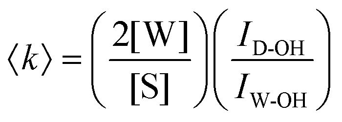 | (1) |
A more general procedure for obtaining 〈k〉 relies on dividing the SC spectrum by the area of a solute intramolecular vibrational band, such as the CH stretch. In such a normalized spectrum, the dangling OH intensity is given by ICH-nD-OH = ID-OH/ICH. This last quantity can be directly translated into 〈k〉 given the values of ΩCH, ΩOH and nCH, which are, respectively, the Raman cross sections of a single CH group and a single water OH group, and the number of CH bonds in a solute molecule, as follows:
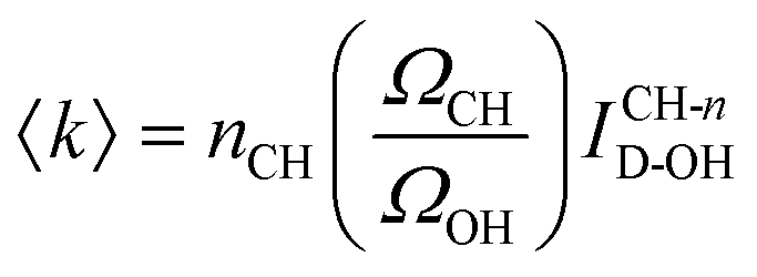 | (2) |
The ratio ΩCH/ΩOH in eqn (2) is estimated using the measured area of the OH band in pure water (IW-OH), the measured area of the CH band (ICH) in the solute, and the concentrations of pure water and solute, as shown below:
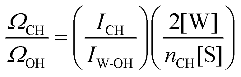 | (3) |
Note that eqn (2) is preferred over eqn (1) because normalization of the SC spectrum to the solute CH band area compensates for any variations in laser intensity (or drifts in optical alignment) that may occur during the Raman spectral acquisition process. Moreover, eqn (2) may also be used to correct the value of 〈k〉 for any difference between the Raman cross section of the dangling OH group and an average OH group in pure water. For example, previously reported calculations have predicted that some dangling OH groups may have a Raman cross section that is approximately half that of an average OH group in pure water.43 If that is assumed to also be the case for the dangling OH groups interacting with a solute fluorine atom, then the appropriate value of ΩCH/ΩOH should be increased by a factor of two (relative to the value obtained using eqn (3)) and thus the resulting values of 〈k〉 (obtained using eqn (2)) would also increase by about a factor of two.
To obtain the dangling OH formation thermodynamics, we consider the process of forming one such dangling OH defect structure in a hydration shell that initially contained no dangling OH defects. This transformation was previously described using a lattice model43 which predicts that, as long as the dangling OH defect formation has a relatively low probability of occurrence (such that 〈k〉 < 1), the equilibrium constant K for the dangling OH formation process should be well approximated by 〈k〉. Thus, the following expressions may be used to obtain the Gibbs energy, enthalpy, and entropy changes associated with the formation of dangling OH defects in the hydration-shell of the solute (where R is the gas constant and T is the absolute temperature):
ΔG = −RT![[thin space (1/6-em)]](https://www.rsc.org/images/entities/char_2009.gif) ln〈k〉 ln〈k〉 | (4) |
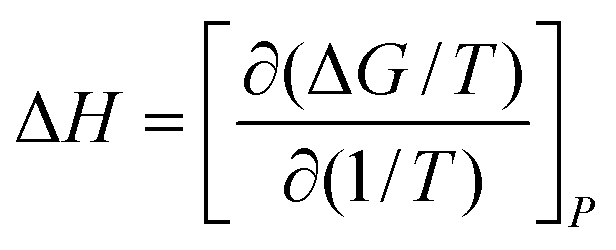 | (5) |
 | (6) |
Computational details
Non-water-bonded hydroxy structures in the hydration shell
The present work is focused on the occurrence of two structures in the hydration shell of MFE, DFE or TFE: hydrogen bond-like hydroxy structures and ‘free’ hydroxy structures, shown in cartoon form in Fig. 1. A hydrogen bond-like structure is defined as a water hydroxy group that directs its hydrogen atom towards a fluorine or hydrogen atom in a –CFH2 (in MFE), –CF2H (DFE) or –CF3 (TFE) group, such that the distance, dOW–H/F, between the water oxygen atom and the alcohol hydrogen or fluorine atom is below 3.5 Å and the angle θ between water oxygen, water hydrogen and alcohol fluorine/hydrogen atoms falls within 160° ≤ θ ≤ 180°.|| A free hydroxy group belongs to a water molecule whose oxygen atom lies no further than 5.69 Å from the carbon atom in the fluoromethyl group (the first hydration shell radius of tetrafluoromethane21) and (i) does not form a hydrogen bond-like structure (see definition above); (ii) does not donate a hydrogen bond (present if dOW–H < 3.5 Å, 160° ≤ θ ≤ 180°) to the alcohol group of the solute; (iii) does not donate a hydrogen bond (present if dOW–H < 3.5 Å, 145° ≤ θ ≤ 180°) to any other water molecule in the simulation box. The collection of hydrogen bond-like structures and free hydroxys will here be referred to as non-water-bonded hydroxy structures. We refer the reader to ref. 42 for a comparison of different definitions employed in quantifying such structures. Free energies of formation of either structure can be calculated via 〈k〉 in eqn (4). In the case of non-water-bonded hydroxys, 〈k〉 equals the sum of hydrogen bond-like structures and excess free hydroxys in solution:| 〈k〉 = OHNWB = OHHBL + ΔOHFree, | (7) |
| ΔOHFree = OHFree,solution − OHUnbound,water. | (8) |
 | ||
| Fig. 1 Schematic representation of the hydration shell of TFE. A hydroxy group forming a hydrogen bond-like structure is highlighted in green, a free hydroxy group is highlighted in purple; we refer to both jointly as non-water-bonded hydroxy groups. Carbon atoms are shown in gray, fluorine in green, oxygen in red and hydrogen in white. The solute and the first hydration shell waters are encircled in blue. | ||
We have previously argued that taking 〈k〉 = OHNWB is in best agreement with Raman-MCR measurements of solutions of 2,2,2-trifluoroethanol,42 implying that non-water-bonded hydroxys are representative of the population of spectroscopically active structures (near 3600 cm−1) in these systems. Eqn (4) was further used to calculate the free energy of formation of hydrogen bond-like structures, with 〈k〉 = OHHBL, which concern non-water-bonded hydroxy groups undergoing direct interactions with the fluoromethyl group.
Molecular dynamics with classical force fields
Each system consists of a cubic box of edge length ≈4 nm containing a single alcohol molecule—MFE, DFE or TFE (all data presented for TFE are taken from ref. 42)—solvated by water. Water is described with the TIP4P-Ew force field.44 The alcohols are modelled with a modified GAFF45 force field, where the Lennard-Jones parameters for the fluorine atoms are taken from ref. 46, those of the hydrogen atoms in –CFH2 and –CF2H groups are taken from ref. 21 and those of the hydrogen atoms in –CH2– groups were described in ref. 42. All of these modified parameters were optimized against the hydration free energies of alkanes and fluoroalkanes. Initial atomic charges on MFE and DFE are calculated through a sequential MP2/6-31G*, RHF/6-31G* RESP47-fitting procedure, as employed for TFE in ref. 42, using the Gaussian 0348 and Antechamber49 software packages. Due to the non-equivalence of the carbon-bonded atoms in the fluoromethyl groups of MFE and DFE, the charges were further refined by extracting conformations of either alcohol every 0.1 ns of a 25 ns simulation of the alcohol in water (following the simulation protocol described below). A RESP fit was conducted for each of these structures and the final partial atomic charges of MFE and DFE result from the mean charges over all structures. ACPYPE50 was used to convert topology files from AMBER51 into Gromacs52–58-readable format.The initial simulation boxes were assembled with the tools available in the Gromacs software package. Each box was minimized first with the steepest-descent and subsequently with the L-BFGS algorithms. Equilibration was done for 100 ps in the NVT ensemble followed by 100 ps in the NpT ensemble. These simulation times are sufficient to equilibrate the volume of the box and the hydration shell of the solute (results not shown). The equilibrated boxes were then simulated for 2 ns in the NpT ensemble, and a frame whose volume was nearest to the average box volume in the simulation was collected. This frame was used as the starting configuration in a 25 ns NVT simulation, with a leapfrog integration scheme, a time-step of 2 fs, and sample collection every 0.1 ps. Langevin dynamics with a 0.05 ps−1 collision frequency were used to minimize perturbations of the system's dynamics. This procedure, from system equilibration to production run, was repeated for each temperature (278 K, 298 K, 318 K, 338 K, 358 K). Coulombic and van der Waals interactions are cut-off at 1.2 nm, the latter being additionally switched to zero between 1.0 and 1.2 nm. PME59 summation was used in calculating long-range electrostatics, with a fourth-order interpolation and 0.1 nm grid spacing. Long-range dispersion corrections were used in the calculation of pressure and energy. LINCS60 constraints were applied to bonds involving hydrogen atoms. Free energies of hydration were calculated with free energy perturbation (FEP) and the BAR method, as described in a previous study.42 In short, a total of 80 steps were used in decoupling coulombic (21 evenly spaced steps) and Lennard-Jones (59 unevenly spaced steps) interactions. Each decoupling simulation ran for 5 ns, after a four-step equilibration protocol as described above, at 298 K, and the phase-space overlap of adjacent decoupling steps was confirmed to be sufficient.
All simulations were carried with Gromacs; statistics on the formation of non-water-bonded structures were collected with VMD61 (in-house scripts).
Symmetry-adapted perturbation theory
Symmetry-adapted perturbation theory (SAPT) calculations were carried with the Psi4 software package62 at the DF-SAPT2 + (CCD)δMP2 level of theory.63–68 Non-valence electrons are treated under the frozen core approximation, a density-fitting approach69,70 is applied to two-electron integrals in self-consistent field calculations and a superposition of atomic densities is used to obtain the initial density-fitted orbitals. The aug-cc-pVTZ71–74 basis sets were used throughout all calculations. This methodology was ranked as the topmost level of theory for SAPT calculations.68 SAPT was used to quantify and decompose the interaction energy between one alcohol molecule and one water molecule, in configurations selected from MD simulations of a single solute in a water box at 298 K. The intermolecular interactions were evaluated in two types of configurations: those where the water molecule forms a hydrogen bond-like structure with the solute according to the criteria outlined above, and, for comparison, those where this structure does not exist. In selecting which structures are submitted to a SAPT calculation, we impose also the criterium that the water oxygen must be beyond 4.5 Å of the carbon atom containing the alcohol function, so that only structures with ‘direct’ interactions between water and the fluorinated methyl groups are reported.Molecular dynamics with potentials from density functional theory
We performed first principles molecular dynamics simulations of MFE, DFE and TFE in water.75 A snap-shot of the MD simulations with classical force fields of TFE in water42 was used to prepare the starting configuration for first-principles simulations. The cubic box was trimmed down to a side length of 1.4 nm, containing the alcohol and 125 water molecules. To build the models for DFE and MFE, one or two fluorine atoms were replaced by hydrogen atoms, respectively. One water molecule situated in a position close to the fluorinated methyl group was selected to represent a hydrogen bond-like structure. This conformation was enforced by restraining the distance between the water oxygen atom and the fluorine atom of the methyl group to 2.6 Å (MFE), 2.8 Å (DFE) and 2.9 Å (TFE) with a force constant of 100 kcal mol−1a0−2 (where a0 is the Bohr radius), while keeping the O–H–F/H angle restrained to 170° with a force constant of 100 kcal mol−1 rad−2. The above distances correspond to the mean value of the oxygen–fluorine distance in 2890 (MFE), 1537 (DFE) and 1314 (TFE) configurations of water–solute hydrogen bond-like structures extracted from MD simulations at 298 K.For all alcohol systems, a 20 ps long simulation was performed using the Quickstep module76 of the CP2K package77 which is based on the Gaussian and plane waves method (GPW) to represent the wavefunction and its augmented extension (GAPW) to describe the electron density.78 We used double zeta valence plus (DZVP) basis set. The interaction between valence and core electrons is described by Geodecker–Teter–Hutter (GTH) norm conserving pseudopotentials. A plane wave expansion for the charge density is employed using an energy cutoff of 500 Ry. The BLYP functional is used as exchange correlation functional and the empirical pair potential in Grimme's D3 method79 was employed for dispersion correction. The equations of motion were integrated with a 0.5 fs time resolution. Atom positions were saved every time-step. From the trajectories, the coordinates of the restrained water molecule were extracted and power spectra for the OH-group facing the fluorinated methyl group were calculated using the TRAVIS80 program. All spectra plots were generated with the matplotlib.pyplot module in Python.81
Results
Raman-MCR spectra
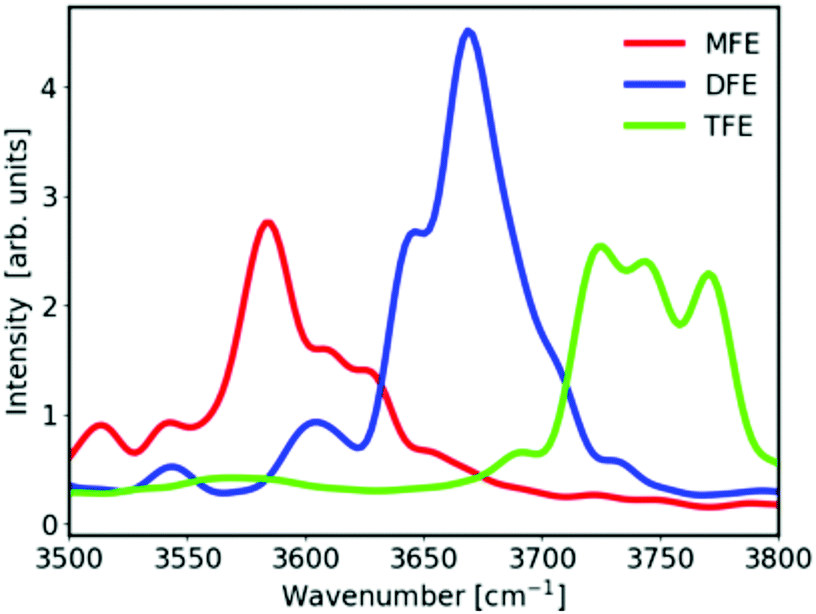
Fig. 2A shows unprocessed Raman spectra obtained at 20 °C for 1 mol dm−3 solutions of MFE, DFE, and TFE, and pure water. A slightly higher background is present in the spectrum of MFE due to fluorescence as this sample is less pure than the other two fluorinated alcohol samples. We note that this level of interfering fluorescence is not detrimental to our analysis given that it can be effectively removed using a linear (or quadratic) background subtraction to produce the SC spectra shown in Fig. 2B (and the associated impurity concentration is far below that of the solute species). The latter SC spectra were obtained using SMCR, from pairs of pure water and solution spectra shown in Fig. 2A. These (unnormalized) SC component spectra clearly indicate a difference in the CH stretch band intensity reflecting the different number of CH groups in each one of the fluorinated alcohols (nCH = 4 in MFE, nCH = 3 in DFE, and nCH = 2 in TFE). Additionally, as highlighted in the inset panel in Fig. 2B, these SC spectra also display vibrational features arising from water molecules whose OH band is perturbed by the solute and thus differ from the OH band of pure water. All three fluorinated alcohols exhibit a prominent and relatively narrow OH feature with a frequency near 3660 cm−1, which has previously been assigned to water dangling OH defects in the hydrogen-bonded hydration-shell structure.42 For all fluorinated solutes, the dangling OH feature is significantly more intense than the previously measured dangling OH in the hydration-shell of EtOH43 (as previously shown42). More interestingly, the intensities of the dangling OH peaks do not increase in proportion to the number of fluorine atom substitutions, suggesting that the dangling OH probability around the single fluorine atom in MFE is larger than that for each of the three fluorine atoms in TFE (as further discussed and quantified below). Moreover, the vibrational frequencies of the dangling OH peaks are significantly redshifted for MFE (3626 cm−1) and DFE (3656 cm−1), relative to TFE and EtOH, both of which have dangling OH frequencies near 3670 cm−1.42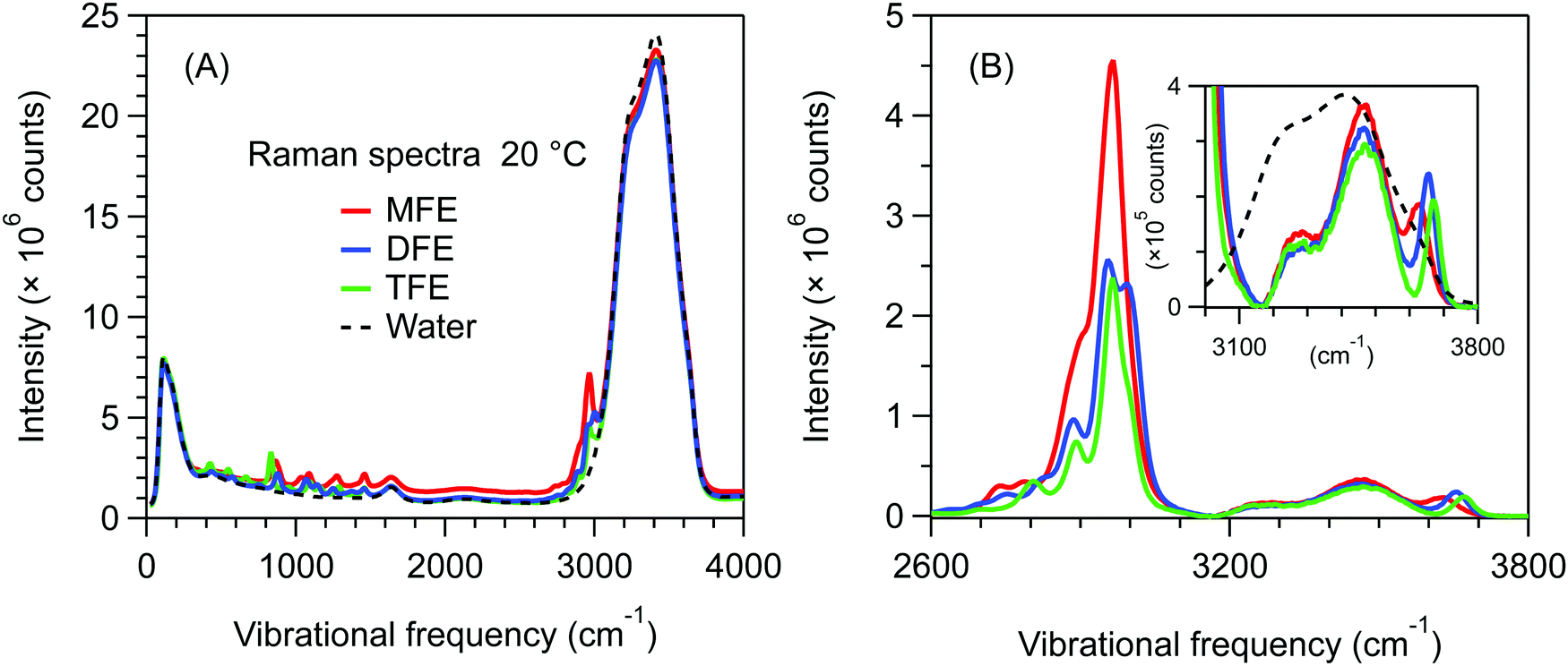 | ||
| Fig. 2 (A) Unprocessed Raman spectra obtained at 20 °C for 1 mol dm−3 solutions of MFE, DFE, and TFE and pure water. (B) Solute-correlated component spectra of MFE, DFE, and TFE, with an expanded view of the OH stretch band region in the inset panel. The dashed curves are the corresponding pure water Raman spectra, arbitrarily scaled to highlight the difference in shape between the pure water and SC OH stretch bands. | ||
Thermodynamics of dangling hydroxy formation
Fig. 3 shows the temperature dependent Raman-MCR SC CH and hydration-shell OH spectra of the three fluorinated ethanol solutes along with the spectra of pure water. These results clearly reveal that the hydration-shells of MFE have a significantly weaker temperature dependence than the hydration-shells of DFE and TFE. Our goal is to use these spectra to obtain the corresponding thermodynamics of forming the dangling OH defect structure around all three fluorinated ethanol solutes from a hydration-shell that contains no dangling OH defects.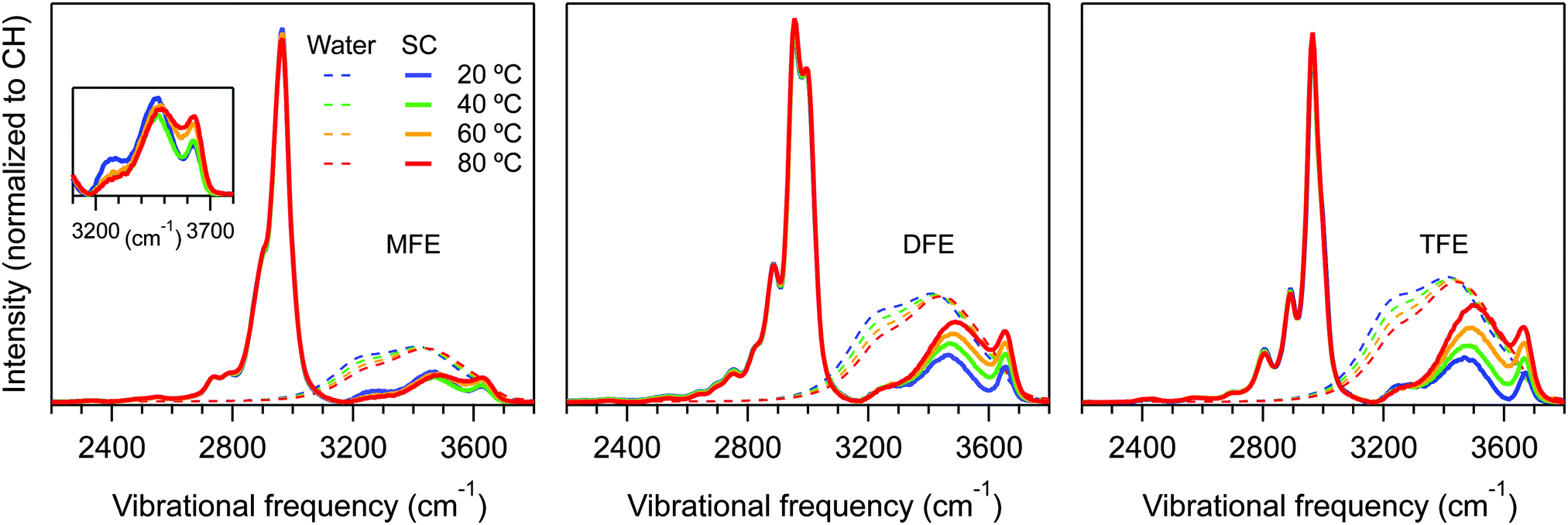 | ||
| Fig. 3 Hydration-shell spectra of MFE, DFE, and TFE normalized to the CH band area. The solid curves represent the solute-correlated (SC) spectra and the dashed curves represent the (arbitrarily scaled) spectra of pure water. | ||
Since the intensity of the dangling OH band is proportional to the probability that such a structure will be found in the hydration shell, its temperature dependence may be used to obtain the Gibbs energy (ΔG), enthalpy (ΔH), and entropy (ΔS) of formation of these defects. However, obtaining the dangling OH band intensity requires subtracting the background intensity underlying the dangling OH band. Since the shape of the background is not precisely known, the background subtraction procedure is the most significant source of error in the resulting ΔG, ΔH and ΔS values. We have determined that the background can be reasonably well approximated by either a Gaussian or cubic polynomial function fit to the points on either side of the dangling OH band of interest. The following results pertain to the average dangling OH band intensities obtained using the two background fitting procedures, and the associated error bars reflect the difference between the band areas obtained in these two ways (see ESI,† for further details).
Fig. 4 shows the dangling OH peaks (solid curves) obtained after subtracting the cubic background (dashed curves) from the SC hydration-shell spectra (transparent solid curves). The corresponding results obtained assuming a Gaussian background shape are shown in ESI,† Fig. S1. The areas of these dangling OH peaks yield 〈k〉, which is the corresponding experimentally determined average number of dangling OH defects in the solute hydration-shell, whose values are plotted in Fig. 5.
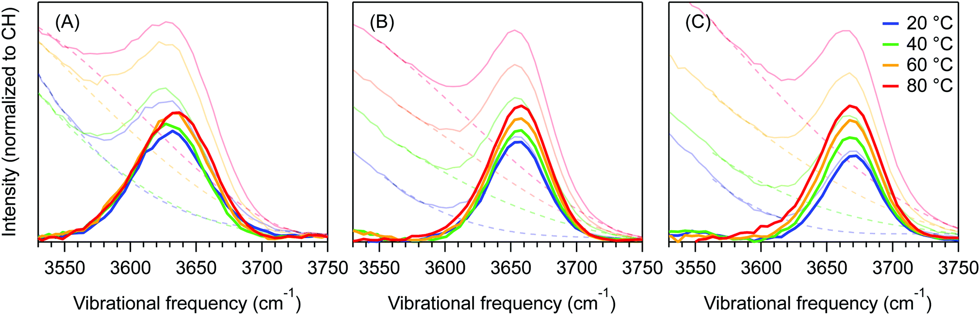 | ||
| Fig. 4 Temperature dependence of the dangling OH peaks in the hydration shell of (A) MFE, (B) DFE and (C) TFE. These peaks were obtained from the respective minimum area non-negative SC spectra (transparent solid curves), after subtracting the background (dashed curves) using a cubic polynomial function. | ||
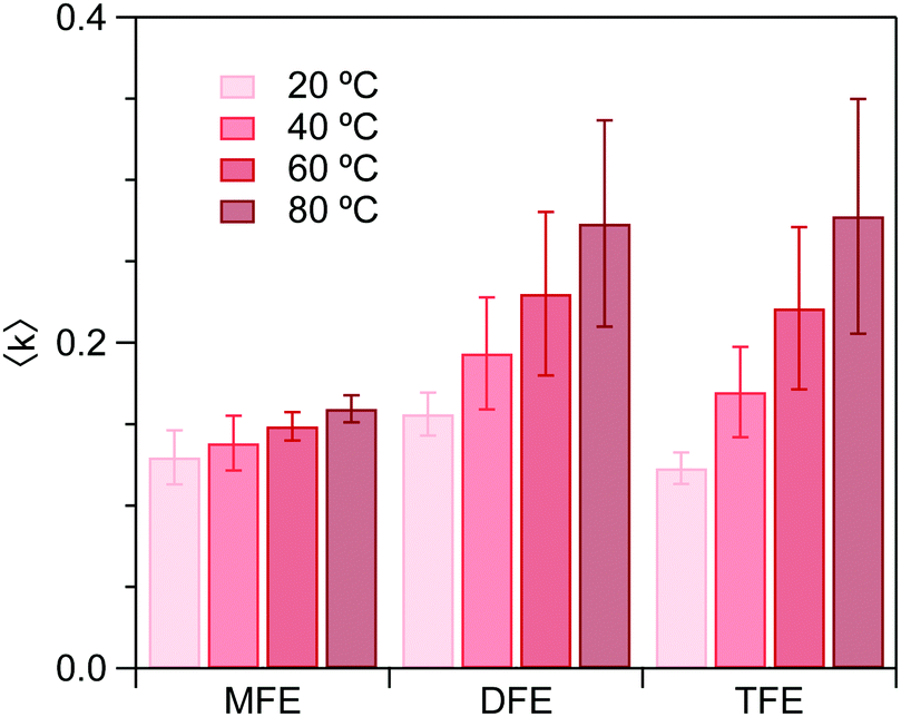 | ||
| Fig. 5 Experimental average number, 〈k〉, of dangling OH structures per hydration shell, determined using the high-frequency OH peak areas. | ||
Fig. 6 shows the ΔG, ΔH and ΔS values obtained from the experimental values of 〈k〉. As can be seen, the enthalpy of forming a dangling OH structure is invariably positive, but increases in magnitude with increasing number of fluorine atoms on the solute. This implies that the OH⋯F interaction is invariably less enthalpically favorable than a water OH⋯O hydrogen-bonded structure, but the OH⋯F interaction is more enthalpically favorable for MFE than for the other two solutes. Specifically, if we assume that the previously measured enthalpy of forming a dangling OH around EtOH (ΔH ≈ 14 kJ mol−142, 43) roughly corresponds to that of breaking a water–water hydrogen bond, then the above ΔH values provide the following estimates of the enthalpy of the OH⋯F hydrogen bond: ΔHTFE ≈ 12 − 14 = −2 kJ mol−1, ΔHDFE ≈ 8 − 14 = −6 kJ mol−1, and ΔHMFE ≈ 3 − 14 = −11 kJ mol−1.
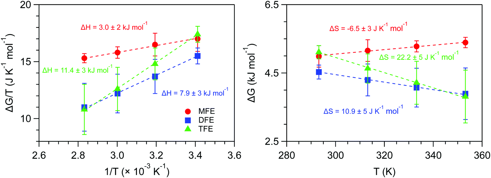 | ||
| Fig. 6 Experimental enthalpy and entropy changes associated with the formation of dangling OH structures with increasing fluorination of the methyl group of ethanol, obtained using the experimental average 〈k〉 values. | ||
The results in Fig. 6 further reveal that the entropy change associated with forming a dangling OH decreases with the number of fluorine atoms on the solute. Moreover, the dangling OH formation ΔS is positive for TFE and DFE but becomes negative for MFE. This implies that the dangling OH species around TFE and DFE are more flexible, while that around MFE is less flexible, relative to a water–water hydrogen-bond. Thus, both the ΔH and ΔS results imply that the single fluorine atom in MFE forms a relatively strong and rigid dangling OH structure, and thus may reasonably be described as an OH⋯F hydrogen bond, while adding more fluorine atoms to the terminal methyl group of ethanol weakens the associated OH⋯F structures and increases their flexibility.
The experimentally-detected dangling hydroxy band arises from non-water-bonded hydroxy groups
Molecular dynamics (MD) simulations were used, together with eqn (4), to determine the temperature dependence of the formation of non-water-bonded hydroxy structures in the hydration shell of the solutes. As mentioned above (Fig. 1), this population actually comprises two subpopulations: hydroxy groups pointing to the tail of the solute (called hydrogen bond-like structures) and free hydroxys. In Fig. 7(A) we quantify the non-water-bonded hydroxy structure population; the hydrogen bond-like subpopulation is shown in panel (B) of the same figure. Comparing these results with experiment (Fig. 5) clarifies that the population, in the MD simulations, that best represents the spectroscopically active population giving rise to the dangling OH peak from experiment is that of non-water-bonded hydroxy groups, that is, both free hydroxy groups and hydrogen bond-like hydroxy groups pointing towards the solute. | ||
| Fig. 7 Predicted average number 〈k〉 of non-water-bonded (panel A) and hydrogen bond-like (panel B) hydroxy structures per hydration shell, quantified with MD simulations in the 278 ≤ T/K ≤ 358 range, for solutions of MFE, DFE and TFE. Data for TFE are obtained from ref. 42. All data are presented in ESI,† Table S5. | ||
This conclusion is further supported by comparing the thermodynamics of formation of non-water-bonded hydroxy structures obtained with simulation (Fig. 8) and experiment (Fig. 6). Even though the absolute values of the enthalpy and entropy of formation differ between experiment and simulation, the observed trends are equivalent. More specifically, the enthalpy required to break a water–water hydrogen bond in the hydration shell of the solute to form either a free hydroxy or a hydrogen-bond-like structure becomes increasingly more unfavourable with increasing fluorine content. Conversely, the entropy change for the same process becomes increasingly more favourable with increasing degree of fluorination and shows a change in sign from MFE to DFE. This change in sign is of particular interest, since it implies that a non-water-bonded structure near a monofluoromethyl group has less conformational freedom than a water–water hydrogen bond in the same region, whereas structures near DFE and TFE are less conformationally restricted. We expect that the qualitative trends shown by the thermodynamic observables calculated from simulation are reliable, despite the fact that these values are necessarily affected by artificial correlations that arise from using periodic boundary conditions. We reduced the magnitude of these effects by choosing a cubic simulation box with edge length at least 10 times larger than the diameter of the simulated molecules. These simulation conditions have been shown to substantially reduce finite-size effects associated with interfacial thermodynamic quantities, even in systems with long range interactions.82–84
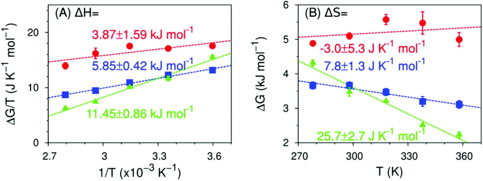 | ||
| Fig. 8 Predicted enthalpy and entropy of formation of a non-water-bonded hydroxy structures (MFE as red circles, DFE as blue squares, TFE as green triangles) in the 278 ≤ T/K ≤ 358 range, calculated from MD simulations using eqn (7), as well as eqn (4) to (6). Dashed lines are linear fits to the data points from which the enthalpy (panel A), the entropy (panel B) and their respective errors are calculated. Data for TFE are taken from ref. 42. See ESI,† Table S6. | ||
The hydrogen bond-like hydroxy subpopulation is the largest of the two subpopulations making up non-water-bonded hydroxy structures at most temperatures in simulation, and thus should dominate the experimental signal. This conclusion is also supported by the computed power spectra of a water hydroxy group restrained to form a hydrogen bond-like structure in Fig. 9. The spectra qualitatively reflect the experimentally observed trend for the position of the water O–H stretching band between 3600 cm−1 and 3700 cm−1 in Fig. 4: the TFE band shows the highest frequency, followed by DFE and MFE. We do, however, observe a shift in the absolute positions of the bands obtained with experimental and computational methods, such that the computed location of the corresponding ethanol band (not shown) lies between the DFE and the TFE band, whereas in the experiment the frequencies for dangling hydroxy structures are about the same for ethanol and TFE.42 Nonetheless, the fact that the occurrence of hydrogen bond-like structures is sufficient to reproduce the varying band locations observed in the Raman-MCR experiments supports our conclusion that these structures provide a useful means of characterizing the hydration shell of each solute, both experimentally and theoretically.
 | ||
| Fig. 9 Predicted power spectra of the water molecule forming a hydrogen bond-like structure with MFE (red), DFE (blue), and TFE (green) computed from first principle simulations of the alcohol molecule in water. The distance between the water molecule oxygen atom and the fluorine atom was restrained to 2.6, 2.8, and 2.9 Å for MFE, DFE, and TFE, respectively. Intensities are unscaled. | ||
Hydrogen bonds and dangling hydroxys
Fig. 10 shows the temperature dependence, calculated using eqn (4), of the formation of hydrogen bond-like structures in the hydration shell of the fluoromethyl groups, such that the hydroxy group points directly at the fluoromethyl moiety. The trends in thermodynamics we have previously observed still hold: the enthalpy becomes more unfavorable with increasing amount of fluorine atoms, the entropy becomes more favorable. However, the absolute values of ΔH and ΔS are markedly different from both the experimental values in Fig. 6 and the theoretical values in Fig. 8 (obtained from all the non-water-bonded hydroxy structures): ΔH ranges from 0 to 6 kJ mol−1 and ΔS from −11 to 3 kJ K−1 mol−1. Since, predominantly, a single such structure is formed at any given time (see ESI,† Fig. S4), the reported free energies follow the balance of attractive water–water and water–fluoromethyl group interactions. The results in Fig. 10 imply that, relative to water–water hydrogen bonds, CF⋯HOH hydrogen-bond like structures in MFE have a similar enthalpy but are more rigid (as they have a more negative entropy). In the case of DFE, the hydrogen bond-like structures are slightly weaker (enthalpically) than water–water hydrogen bonds and again moderately more rigid, while those to TFE are much weaker compared to water–water hydrogen bonds, and slightly more flexible. In other words, water molecules can form hydrogen bonds with the fluorine atom in MFE, dangling hydroxys near the fluorine atoms in TFE and something in between for DFE.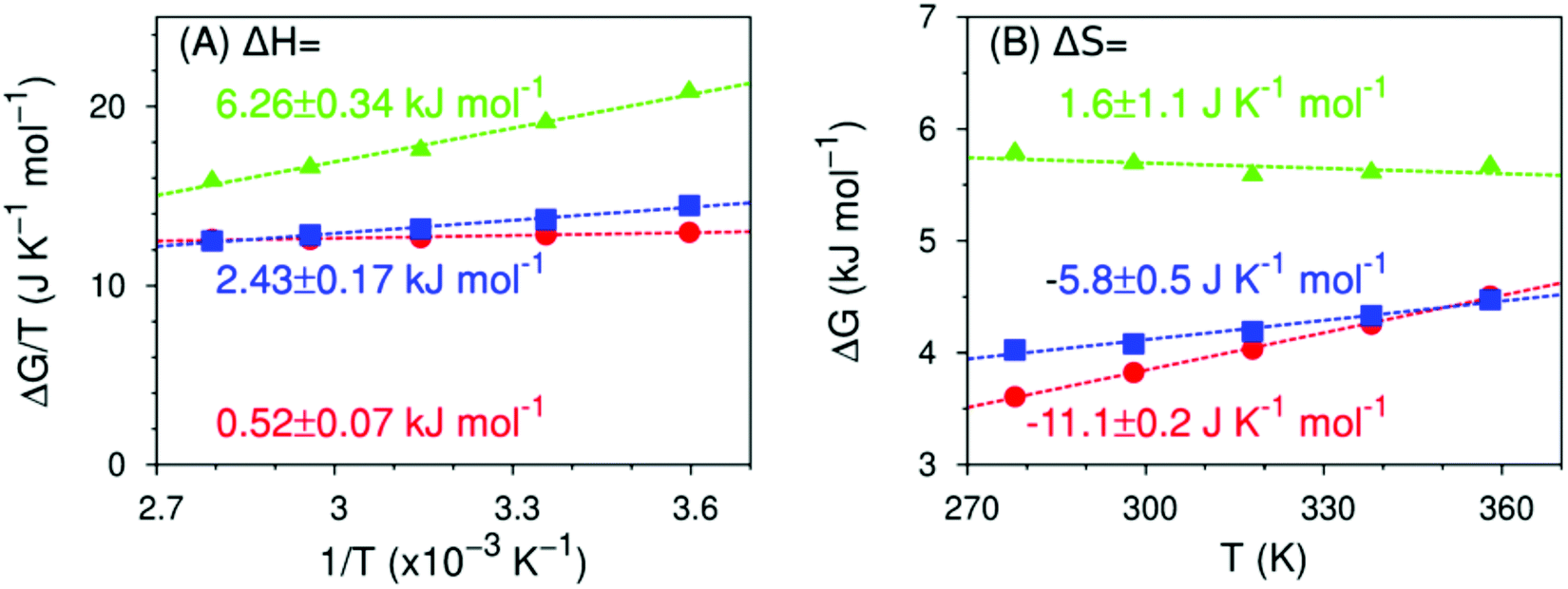 | ||
| Fig. 10 Predicted enthalpy and entropy of formation of a hydrogen bond-like structure (MFE as red circles, DFE as blue squares, TFE as green triangles) in the 278 ≤ T/K ≤ 358 K range, calculated from MD simulations using eqn (4) to (6). Dashed lines are linear fits to the data points from which the enthalpy (panel A), the entropy (panel B) and their respective errors are calculated. Data for TFE are extracted from ref. 42. Refer to ESI,† Table S6. | ||
A stepwise transition from hydrophilic to hydrophobic
Given the above results, it is tempting to label –CFH2 as hydrophilic and –CF3 as hydrophobic. We emphasize, however, that differences in the hydrophobicity of these groups will also indirectly reflect different water–water interactions in their hydration shells, which we do not explore here.85 To test the validity of these labels we have calculated hydration free energies (ΔGHyd) of ethanol (EtOH), MFE, DFE and TFE at 298 K from available experimental data (see ESI,† Tables S1 and S2). The hydration free energy varies as MFE < DFE < EtOH < TFE. Importantly, our simulations (see ESI,† Section S2) show that the dominant contribution to this trend indeed comes from the tail of the alcohols, indicating that the labels given to mono-, di- and trifluorinated groups are appropriate.Discrete, attractive, solute–water interactions of hydrophobes and hydrophiles
Direct solute–water interactions can be quantified using symmetry-adapted perturbation theory calculations, the results of which are shown in Fig. 11A and ESI,† Fig. S5A for several water–solute dimer configurations in vacuum. These configurations were extracted from MD simulations of the solute in a water box, and are therefore representative of a fully hydrated solute. The variation of the total interaction energy between a solute and a single water molecule along the distance between the water oxygen atom and the solute's closest fluorine atom is distinct between MFE, DFE or TFE only when the water molecule forms a hydrogen bond-like structure with the solute. For these configurations, the interaction becomes less favorable with increasing number of fluorine atoms (Fig. 11A). The observed trend in stability is in agreement with the enthalpies of formation of hydrogen bond-like structures in Fig. 6, 8 and 10. When the water molecule does not form such a structure, the mean value of the interaction energy distributions is close to zero for the 3 alcohols (ESI,† Fig. S5A).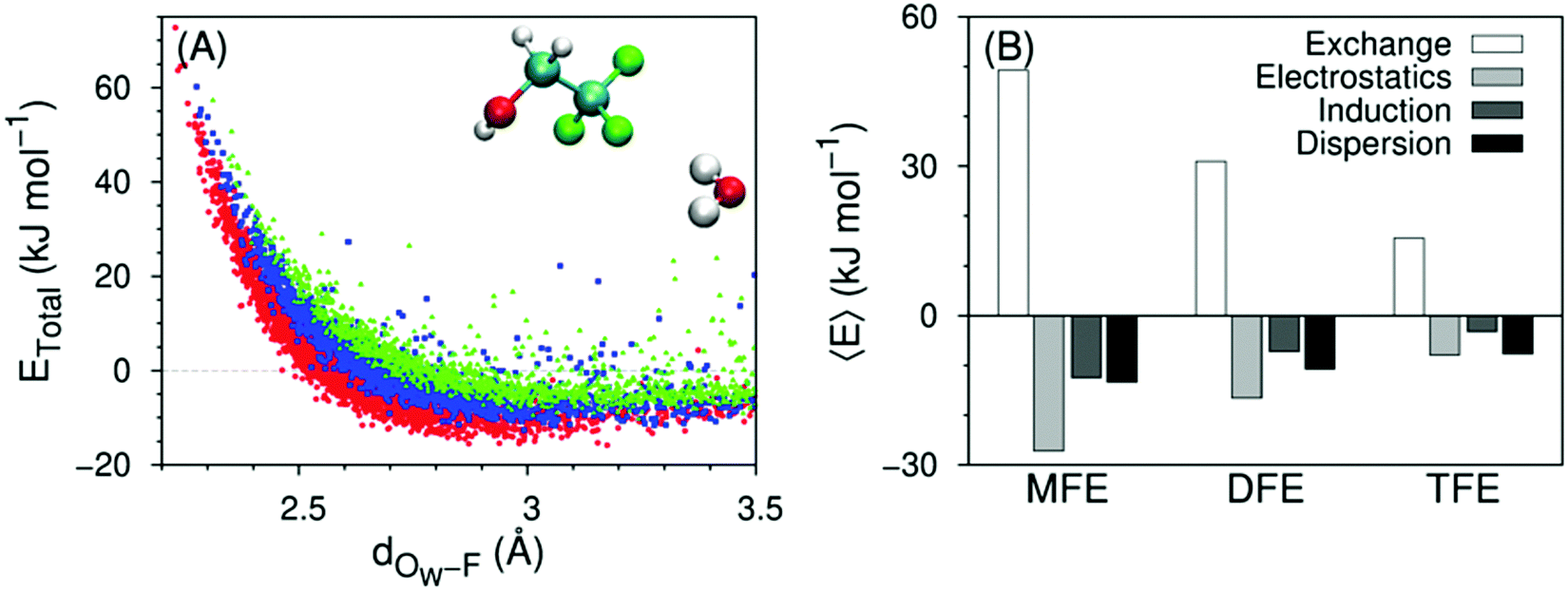 | ||
| Fig. 11 (A) Total interaction energy vs. distance for water–solute dimers forming a hydrogen bond-like structure (water-MFE as red circles, water–DFE as blue squares, water–TFE as green triangles), calculated at the DF-SAPT2 + (CCD)δMP2/aug-cc-pVTZ level of theory. The distance corresponds to the closest water oxygen–fluorine pair. Configurations are extracted from MD simulations at 298 K. The inset molecules represent a conformation of a water–TFE dimer corresponding to one of the plotted data points. (B) Average energy components 〈E〉, calculated for distances above that where the total energy becomes attractive (2.5, 2.6 and 2.8 Å for MFE, DFE and TFE, respectively). Data for TFE are taken from ref. 42. The number of points in each data set is MFE: 2890; DFE: 1537; TFE: 1314. Related with Fig. S5, S6 and Table S8 (ESI†). | ||
Conveniently, SAPT calculations allow us to decompose the total interaction energy into electrostatics, London dispersion, induction and exchange contributions, shown as averages in Fig. 11B (the dependence of the different contributions on water–fluorine distance is collected in ESI,† Fig. S6). All contributions decrease in magnitude with increasing degree of fluorination. However, the ratio of different attractive contributions (ESI,† Fig. S5B) is more informative: whereas electrostatics is always twice as large as induction, the dispersion:induction ratio increases from one to two along the transition from MFE to TFE and the dispersion:electrostatics ratio increases from one half to one.
Concluding remarks
We have investigated the sequential fluorination of a methyl group (in ethanol) and the associated changes in hydrophobicity, hydration shell structure and thermodynamics. The hydrophobicity of a methyl group scales non-monotonically with the degree of fluorination, as the hydrophobicity of a methyl group initially decreases and then increases with the addition of 1 to 3 fluorine atoms. We have shown that a specific hydration shell structure, CF⋯HOH, meeting geometric criteria commonly used to define water–solute hydrogen bonds, is present in aqueous solutions of each of these alcohols. Further, the free energy, enthalpy and entropy of formation of this structure, which are experimentally accessible using spectroscopic methods, are sufficiently different as to allow for a categorization of the structures into either hydrogen bond (MFE) or dangling hydroxy (TFE), or a structure exhibiting intermediate spectroscopic and thermodynamics features (DFE). Moreover, both enthalpy and entropy are indispensable for our understanding of hydrogen bonds. The hydrogen bond donated by water to the fluorine in MFE actually has comparable enthalpy to that of water–water hydrogen bonds; the former is overall much weaker than the later only because of its high entropic cost. Finally, the balance of attractive solute–water interactions, namely London dispersion and electrostatics, closely follows the categorization: hydrogen bonds are highly directional owing to a large electrostatic stabilization from the aligned dipoles of the C–F and the H–O bonds; loosely bonded dangling hydroxys have a much weaker stabilizing contribution of electrostatics, which is near-exactly matched by London dispersion. Our results demonstrate that the combined use of Raman-MCR and theoretical calculations may be used to quantify and mechanistically explain subtle changes in hydrogen bond character and local hydrophobicity associated with sequential fluorination of a methyl group, and suggest that the same strategy could be extended to other solute–solvent interactions.The effects of mono-, di- and trifluorination on solute–water interactions reported here and, more generally, the importance of understanding the entropic and enthalpic signature of solute–water hydrogen bonds (relative to water–water hydrogen bonds in the bulk liquid) have potentially important implications for drug design and for our understanding of biological systems. This importance is illustrated by the surprising capability of fluorinated BPTI derivatives to inhibit β-trypsin. The β-trypsin–BPTI binding pocket contains up to five water molecules, which interact with nearby amino acids and play a role in the binding affinity. Wild-type BPTI has an arginine amino acid in the binding loop. Replacing arginine by ethylglycine dramatically reduces BPTI's inhibitory capacity—unsurprising, given that the long, positively charged side chain of arginine was replaced by a short and electrostatically neutral one (CH2CH3). Replacing the methyl group in ethylglycine by di- or trifluorinated variants, however, recovers BPTI's inhibitory capacity to wild-type levels.23 Our results point towards a mechanistic explanation of these changes.
Predicting whether two molecules interact mainly through electrostatics or dispersion is a long-standing challenge, and answering it typically requires a combination of methods which have limited application in condensed phase systems.86–88 Here we have demonstrated that hydration shell spectroscopy accompanied by simulation can be used to elucidate such interactions. Increasing enthalpic cost and entropic gain of forming hydrogen bond-like structures does correlate with a decrease in the electrostatics:dispersion ratio for ethanol, MFE, DFE and TFE.42 Thus it is possible to link electrostatic and dispersive contributions to the formation of different solute–water hydrogen bond-like structures and their influence on hydration thermodynamics.
Author contributions
J. R. R. performed classical simulations, SAPT calculations; D. M. O. performed experiments; P. I. performed first principles simulations; D. B. A. supervised experiments; A. V. V. supervised classical simulations and designed initial project. All authors contributed to project design, analyses and writing.Conflicts of interest
There are no conflicts of interest to declare.Acknowledgements
Support for D. B.-A. and D. M. O. was provided by the US National Science Foundation (CHE-1763581) and Purdue University. J. R. R., P. I. and A. V. V. acknowledge support by the Deutsche Forschungsgemeinschaft (SPP 1807). Computational resources provided by the North-German Supercomputing Alliance (HLRN) and by the ZEDAT at Freie Universität Berlin are gratefully acknowledged. Open Access funding provided by the Max Planck Society.References
- A. J. Patel, P. Varilly, S. N. Jamadagni, M. F. Hagan, D. Chandler and S. Garde, J. Phys. Chem. B, 2012, 116, 2498–2503 CrossRef CAS.
- P. Ball, Chem. Rev., 2008, 108, 74–108 CrossRef CAS.
- M.-C. Bellissent-Funel, A. Hassanali, M. Havenith, R. Henchman, P. Pohl, F. Sterpone, D. van der Spoel, Y. Xu and A. E. Garcia, Chem. Rev., 2016, 116, 7673–7697 CrossRef CAS.
- D. Chandler, Nature, 2005, 437, 640 CrossRef CAS.
- D. Ben-Amotz, Annu. Rev. Phys. Chem., 2016, 67, 617–638 CrossRef CAS.
- G. Schirò, Y. Fichou, F.-X. Gallat, K. Wood, F. Gabel, M. Moulin, M. Härtlein, M. Heyden, J.-P. Colletier and A. Orecchini, et al. , Nat. Commun., 2015, 6, 6490 CrossRef.
- P. Anilkumar, T. B. Lawson, S. Abbina, J. T. A. Mäkelä, R. C. Sabatelle, L. E. Takeuchi, B. D. Snyder, M. W. Grinstaff and J. N. Kizhakkedathu, Nat. Commun., 2020, 11, 2139 CrossRef CAS.
- D. I. Fried, D. Bednarski, M. Dreifke, F. J. Brieler, M. Thommes and M. Fröba, J. Mater. Chem. B, 2015, 3, 2341–2349 RSC.
- G.-P. Hao, G. Mondin, Z. Zheng, T. Biemelt, S. Klosz, R. Schubel, A. Eychmüller and S. Kaskel, Angew. Chem., Int. Ed., 2015, 54, 1941–1945 CrossRef CAS.
- I. K. Ilic, M. Perovic and C. Liedel, ChemSusChem, 2020, 13, 1856–1863 CrossRef CAS.
- V. Sahu, S. Shekhar, P. Ahuja, G. Gupta, S. K. Singh, R. K. Sharma and G. Singh, RSC Adv., 2013, 3, 3917–3924 RSC.
- Y.-T. Kim and T. Mitani, J. Power Sources, 2006, 158, 1517–1522 CrossRef CAS.
- L. Kou and C. Gao, Nanoscale, 2013, 5, 4370–4378 RSC.
- A. Wittkopp and P. R. Schreiner, Chem. – Eur. J., 2003, 9, 407–414 CrossRef CAS.
- J. J. Gajewski, Acc. Chem. Res., 1997, 30, 219–225 CrossRef CAS.
- J. B. F. N. Engberts and M. J. Blandamer, Chem. Commun., 2001, 1701–1708 RSC.
- Y. Luo, H. Ma, S. Zhang, D. Zheng, P. Che, X. Liu, M. Zhang, J. Gao and J. Xu, J. Am. Chem. Soc., 2020, 142, 6085–6092 CrossRef.
- Q. Xiao, M. Delbianco, S. E. Sherman, A. M. Reveron Perez, P. Bharate, A. Pardo-Vargas, C. Rodriguez-Emmenegger, N. Y. Kostina, K. Rahimi, D. Söder, M. Möller, M. L. Klein, P. H. Seeberger and V. Percec, Proc. Natl. Acad. Sci. U. S. A., 2020, 117, 11931–11939 CrossRef CAS.
- T. Kawasaki, M. Tokuhiro, N. Kimizuka and T. Kunitake, J. Am. Chem. Soc., 2001, 123, 6792–6800 CrossRef CAS.
- S. E. Boyken, Z. Chen, B. Groves, R. A. Langan, G. Oberdorfer, A. Ford, J. M. Gilmore, C. Xu, F. DiMaio, J. H. Pereira, B. Sankaran, G. Seelig, P. H. Zwart and D. Baker, Science, 2016, 352, 680–687 CrossRef CAS.
- J. R. Robalo and A. Vila Verde, Phys. Chem. Chem. Phys., 2019, 2029–2038 RSC.
- E. Camerino, D. M. Wong, F. Tong, F. Körber, A. D. Gross, R. Islam, E. Viayna, J. M. Mutunga, J. Li and M. M. Totrov, et al. , Bioorg. Med. Chem. Lett., 2015, 25, 4405–4411 CrossRef CAS.
- S. Ye, B. Loll, A. A. Berger, U. Mülow, C. Alings, M. C. Wahl and B. Koksch, Chem. Sci., 2015, 6, 5246–5254 RSC.
- B. Zheng, S. V. D’Andrea, L.-Q. Sun, A. X. Wang, Y. Chen, P. Hrnciar, J. Friborg, P. Falk, D. Hernandez, F. Yu, A. K. Sheaffer, J. O. Knipe, K. Mosure, R. Rajamani, A. C. Good, K. Kish, J. Tredup, H. E. Klei, M. Paruchuri, A. Ng, Q. Gao, R. A. Rampulla, A. Mathur, N. A. Meanwell, F. McPhee and P. M. Scola, ACS Med. Chem. Lett., 2018, 9, 143–148 CrossRef CAS.
- A. A. Berger, J. S. Völler, N. Budisa and B. Koksch, Acc. Chem. Res., 2017, 50, 2093–2103 CrossRef CAS.
- E. N. G. Marsh, Acc. Chem. Res., 2014, 47, 2878–2886 CrossRef CAS.
- B. C. Buer, B. J. Levin and E. N. G. Marsh, J. Am. Chem. Soc., 2012, 134, 13027–13034 CrossRef CAS.
- M. Salwiczek, E. K. Nyakatura, U. I. M. Gerling, S. Ye and B. Koksch, Chem. Soc. Rev., 2012, 41, 2135–2171 RSC.
- D. Giménez, C. Andreu, M. del Olmo, T. Varea, D. Diaz and G. Asensio, Bioorg. Med. Chem., 2006, 14, 6971–6978 CrossRef.
- H. Meng and K. Kumar, J. Am. Chem. Soc., 2007, 129, 15615–15622 CrossRef CAS.
- Y. Zafrani, G. Sod-Moriah, D. Yeffet, A. Berliner, D. Amir, D. Marciano, S. Elias, S. Katalan, N. Ashkenazi and M. Madmon, et al. , J. Med. Chem., 2019, 62, 5628–5637 CrossRef CAS.
- J. A. Erickson and J. I. McLoughlin, J. Org. Chem., 1995, 60, 1626–1631 CrossRef CAS.
- Y. Zafrani, D. Yeffet, G. Sod-Moriah, A. Berliner, D. Amir, D. Marciano, E. Gershonov and S. Saphier, J. Med. Chem., 2017, 60, 797–804 CrossRef CAS.
- C. D. Sessler, M. Rahm, S. Becker, J. M. Goldberg, F. Wang and S. J. Lippard, J. Am. Chem. Soc., 2017, 139, 9325–9332 CrossRef CAS.
- B. E. Smart, J. Fluorine Chem., 2001, 109, 3–11 CrossRef CAS.
- R. Pollice and P. Chen, J. Am. Chem. Soc., 2019, 141, 3489–3506 CrossRef CAS.
- I. T. Horváth and J. Rábai, Science, 1994, 266, 72–75 CrossRef.
- J. G. Davis, K. P. Gierszal, P. Wang and D. Ben-Amotz, Nature, 2012, 491, 582–585 CrossRef CAS.
- K. P. Gierszal, J. G. Davis, M. D. Hands, D. S. Wilcox, L. V. Slipchenko and D. Ben-Amotz, J. Phys. Chem. Lett., 2011, 2, 2930–2933 CrossRef CAS.
- W. H. Lawton and E. A. Sylvestre, Technometrics, 1971, 13, 617–633 CrossRef.
- P. Perera, M. Wyche, Y. Loethen and D. Ben-Amotz, J. Am. Chem. Soc., 2008, 130, 4576–4577 CrossRef CAS.
- J. R. Robalo, L. M. Streacker, D. Mendes de Oliveira, P. Imhof, D. Ben-Amotz and A. V. Verde, J. Am. Chem. Soc., 2019, 141, 15856–15868 CrossRef CAS.
- J. G. Davis, B. M. Rankin, K. P. Gierszal and D. Ben-Amotz, Nat. Chem., 2013, 5, 796 CrossRef CAS.
- H. W. Horn, W. C. Swope, J. W. Pitera, J. D. Madura, T. J. Dick, G. L. Hura and T. Head-Gordon, J. Chem. Phys., 2004, 120, 9665–9678 CrossRef CAS.
- J. Wang, R. M. Wolf, J. W. Caldwell, P. A. Kollman and D. A. Case, J. Comput. Chem., 2004, 25, 1157–1174 CrossRef CAS.
- J. R. Robalo, S. Huhmann, B. Koksch and A. Vila Verde, Chem, 2017, 3, 881–897 CAS.
- P. Cieplak, W. D. Cornell, C. Bayly and P. A. Kollman, J. Comput. Chem., 1995, 16, 1357–1377 CrossRef CAS.
- M. J. Frisch, G. W. Trucks, H. B. Schlegel, G. E. Scuseria, M. A. Robb, J. R. Cheeseman, J. A. Montgomery, Jr., T. Vreven, K. N. Kudin, J. C. Burant, J. M. Millam, S. S. Iyengar, J. Tomasi, V. Barone, B. Mennucci, M. Cossi, G. Scalmani, N. Rega, G. A. Petersson, H. Nakatsuji, M. Hada, M. Ehara, K. Toyota, R. Fukuda, J. Hasegawa, M. Ishida, T. Nakajima, Y. Honda, O. Kitao, H. Nakai, M. Klene, X. Li, J. E. Knox, H. P. Hratchian, J. B. Cross, V. Bakken, C. Adamo, J. Jaramillo, R. Gomperts, R. E. Stratmann, O. Yazyev, A. J. Austin, R. Cammi, C. Pomelli, J. W. Ochterski, P. Y. Ayala, K. Morokuma, G. A. Voth, P. Salvador, J. J. Dannenberg, V. G. Zakrzewski, S. Dapprich, A. D. Daniels, M. C. Strain, O. Farkas, D. K. Malick, A. D. Rabuck, K. Raghavachari, J. B. Foresman, J. V. Ortiz, Q. Cui, A. G. Baboul, S. Clifford, J. Cioslowski, B. B. Stefanov, G. Liu, A. Liashenko, P. Piskorz, I. Komaromi, R. L. Martin, D. J. Fox, T. Keith, M. A. Al-Laham, C. Y. Peng, A. Nanayakkara, M. Challacombe, P. M. W. Gill, B. Johnson, W. Chen, M. W. Wong, C. Gonzalez and J. A. Pople, Gaussian 03, Revision E.01, 2004 Search PubMed.
- J. Wang, W. Wang, P. A. Kollman and D. A. Case, J. Mol. Graphics Modell., 2006, 25, 247–260 CrossRef CAS.
- A. W. S. da Silva and W. F. Vranken, BMC Res. Notes, 2012, 5, 1 CrossRef.
- D. A. Case, V. Babin, J. T. Berryman, R. M. Betz, Q. Cai, D. S. Cerutti, T. E. Cheatham III, T. A. Darden, R. E. Duke, H. Gohlke, A. W. Goetz, S. Gusarov, N. Homeyer, P. Janowski, J. Kaus, I. Kolossváry, A. Kovalenko, T. S. Lee, S. LeGrand, T. Luchko, R. Luo, B. Madej, K. M. Merz, F. Paesani, D. R. Roe, A. Roitberg, C. Sagui, R. Salomon-Ferrer, G. Seabra, C. L. Simmerling, W. Smith, J. Swails, R. C. Walker, J. Wang, R. M. Wolf, X. Wu and P. A. Kollman, AMBER 14, University of California, San Francisco, 2014 Search PubMed.
- H. Berendsen, D. van der Spoel and R. van Drunen, Comput. Phys. Commun., 1995, 91, 43–56 CrossRef CAS.
- E. Lindahl, B. Hess and D. van der Spoel, J. Mol. Model., 2001, 7, 306–317 CrossRef CAS.
- D. Van Der Spoel, E. Lindahl, B. Hess, G. Groenhof, A. E. Mark and H. J. C. Berendsen, J. Comput. Chem., 2005, 26, 1701–1718 CrossRef CAS.
- B. Hess, C. Kutzner, D. Van Der Spoel and E. Lindahl, J. Chem. Theory Comput., 2008, 4, 435–447 CrossRef CAS.
- S. Pronk, S. Páll, R. Schulz, P. Larsson, P. Bjelkmar, R. Apostolov, M. R. Shirts, J. C. Smith, P. M. Kasson, D. van der Spoel, B. Hess and E. Lindahl, Bioinformatics, 2013, 29, 845–854 CrossRef CAS.
- S. Páll, M. J. Abraham, C. Kutzner, B. Hess and E. Lindahl, International Conference on Exascale Applications and Software, 2014, pp. 3–27.
- M. J. Abraham, T. Murtola, R. Schulz, S. Páll, J. C. Smith, B. Hess and E. Lindahl, SoftwareX, 2015, 1, 19–25 CrossRef.
- U. Essmann, L. Perera, M. L. Berkowitz, T. Darden, H. Lee and L. G. Pedersen, J. Chem. Phys., 1995, 103, 8577–8593 CrossRef CAS.
- B. Hess, H. Bekker, H. J. C. Berendsen and J. G. E. M. Fraaije, J. Comput. Chem., 1997, 18, 1463–1472 CrossRef CAS.
- W. Humphrey, A. Dalke and K. Schulten, J. Mol. Graphics, 1996, 14, 33–38 CrossRef CAS.
- R. M. Parrish, L. A. Burns, D. G. A. Smith, A. C. Simmonett, A. E. DePrince, E. G. Hohenstein, U. Bozkaya, A. Y. Sokolov, R. Di Remigio, R. M. Richard, J. F. Gonthier, A. M. James, H. R. McAlexander, A. Kumar, M. Saitow, X. Wang, B. P. Pritchard, P. Verma, H. F. Schaefer, K. Patkowski, R. A. King, E. F. Valeev, F. A. Evangelista, J. M. Turney, T. D. Crawford and C. D. Sherrill, J. Chem. Theory Comput., 2017, 13, 3185–3197 CrossRef CAS.
- B. Jeziorski, R. Moszynski and K. Szalewicz, Chem. Rev., 1994, 94, 1887–1930 CrossRef CAS.
- E. G. Hohenstein and C. D. Sherrill, Wiley Interdiscip. Rev.: Comput. Mol. Sci., 2012, 2, 304–326 CAS.
- R. M. Parrish, E. G. Hohenstein and C. D. Sherrill, J. Chem. Phys., 2013, 139, 174102 CrossRef.
- E. G. Hohenstein, H. M. Jaeger, E. J. Carrell, G. S. Tschumper and C. D. Sherrill, J. Chem. Theory Comput., 2011, 7, 2842–2851 CrossRef CAS.
- E. G. Hohenstein and C. D. Sherrill, J. Chem. Phys., 2010, 133, 104107 CrossRef.
- T. M. Parker, L. A. Burns, R. M. Parrish, A. G. Ryno and C. D. Sherrill, J. Chem. Phys., 2014, 140, 094106 CrossRef.
- E. G. Hohenstein and C. D. Sherrill, J. Chem. Phys., 2010, 132, 184111 CrossRef.
- E. G. Hohenstein and C. D. Sherrill, J. Chem. Phys., 2010, 133, 014101 CrossRef.
- T. H. Dunning Jr, J. Chem. Phys., 1989, 90, 1007–1023 CrossRef.
- R. A. Kendall, T. H. Dunning Jr and R. J. Harrison, J. Chem. Phys., 1992, 96, 6796–6806 CrossRef CAS.
- F. Weigend, A. Köhn and C. Hättig, J. Chem. Phys., 2002, 116, 3175–3183 CrossRef CAS.
- F. Weigend, Phys. Chem. Chem. Phys., 2002, 4, 4285–4291 RSC.
- D. Marx and J. Hutter, Ab Initio Molecular Dynamics: Theory and Implementation, in Modern Methods and Algorithms of Quantum Chemistry, John von Neumann Institute for Computing, Jülich, 2000, vol. 3, pp. 329–477 Search PubMed.
- J. VandeVondele, M. Krack, F. Mohamed, M. Parrinello, T. Chassaing and J. Hutter, Comput. Phys. Commun., 2005, 167, 103–128 CrossRef CAS.
- J. Hutter, M. Iannuzzi, F. Schiffmann and J. VandeVondele, Wiley Interdiscip. Rev.: Comput. Mol. Sci., 2014, 4, 15–25 CAS.
- G. Lippert, J. Hutter and M. Parrinello, Theor. Chem. Acc., 1999, 103, 124–140 Search PubMed.
- S. Grimme, J. Antony, S. Ehrlich and H. Krieg, J. Chem. Phys., 2010, 132, 154104 CrossRef.
- M. Brehm and B. Kirchner, J. Chem. Inf. Model., 2011, 51, 2007–2023 CrossRef CAS.
- J. D. Hunter, Comput. Sci. Eng., 2007, 9, 90–95 Search PubMed.
- P. Orea, J. López-Lemus and J. Alejandre, J. Chem. Phys., 2005, 123, 114702 CrossRef.
- M. González-Melchor, F. Bresme and J. Alejandre, J. Chem. Phys., 2005, 122, 104710 CrossRef.
- F. G. J. Longford, J. W. Essex, C.-K. Skylaris and J. G. Frey, J. Chem. Phys., 2018, 148, 214704 CrossRef.
- S. Roy, B. Biswas, N. Ghosh, P. C. Singh and J. A. Mondal, J. Phys. Chem. C, 2019, 123, 27012–27019 CrossRef CAS.
- H. C. Gottschalk, A. Poblotzki, M. A. Suhm, M. M. Al-Mogren, J. Antony, A. A. Auer, L. Baptista, D. M. Benoit, G. Bistoni, F. Bohle, R. Dahmani, D. Firaha, S. Grimme, A. Hansen, M. E. Harding, M. Hochlaf, C. Holzer, G. Jansen, W. Klopper, W. A. Kopp, L. C. Kröger, K. Leonhard, H. Mouhib, F. Neese, M. N. Pereira, I. S. Ulusoy, A. Wuttke and R. A. Mata, J. Chem. Phys., 2018, 148, 014301 CrossRef.
- J. P. Wagner and P. R. Schreiner, Angew. Chem., Int. Ed., 2015, 54, 12274–12296 CrossRef CAS.
- R. A. Mata and M. A. Suhm, Angew. Chem., Int. Ed., 2017, 56, 11011–11018 CrossRef CAS.
Footnotes |
| † Electronic supplementary information (ESI) available: Temperature dependence of the dangling OH peaks obtained after subtracting the background using a Gaussian fit; experimental Henry's law coefficients and hydration free energies for EtOH, MFE, DFE, and TFE; simulation hydration free energies for MFE, DFE, TFE; partial charges of the alcohol oxygen and the fluorines in MFE, DFE, TFE; probabilities of having exactly 1 or 2 hydrogen bond-like structures in the hydration shell of MFE, DFE, TFE; SAPT for water-bonded and hydrogen bond-like structures; tables with all simulation data presented in graphical form in the main text. See DOI: 10.1039/d0cp04205f |
| ‡ These authors have contributed equally. |
| § Present address: Computer Chemistry Center, Friedrich-Alexander Universität (FAU) Erlangen-Nürnberg, Nägelsbachstraße 25, 91052 Erlangen, Germany. |
| ¶ Present address: University of Duisburg-Essen, Faculty of Physics, Lotharstrasse 1, 47057 Duisburg, Germany. |
| || In our prior publication concerning TFE and ethanol,42 this structure was termed “dangling”; the new nomenclature was adopted here because it is both more general and more descriptive, as well as easy to understand. |
| This journal is © the Owner Societies 2020 |