
 Open Access Article
 This Open Access Article is licensed under a Creative Commons Attribution-Non Commercial 3.0 Unported Licence
Towards molecular movies with X-ray photon correlation spectroscopy
Fivos
Perakis
 a and
Christian
Gutt
b
a and
Christian
Gutt
b
aDepartment of Physics, AlbaNova University Center, Stockholm University, S-106 91 Stockholm, Sweden. E-mail: f.perakis@fysik.su.se
bDepartment Physik, Universität Siegen, D-57072 Siegen, Germany. E-mail: christian.gutt@uni-siegen.de
First published on 27th August 2020
Abstract
In this perspective article we highlight research opportunities and challenges in probing structural dynamics of molecular systems using X-ray Photon Correlation Spectroscopy (XPCS). The development of new X-ray sources, such as 4th generation storage rings and X-ray free-electron lasers (XFELs), provides promising new insights into molecular motion. Employing XPCS at these sources allows to capture a very broad range of timescales and lengthscales, spanning from femtoseconds to minutes and atomic scales to the mesoscale. Here, we discuss the scientific questions that can be addressed with these novel tools for two prominent examples: the dynamics of proteins in biomolecular condensates and the dynamics of supercooled water. Finally, we provide practical tips for designing and estimating feasibility of XPCS experiments as well as on detecting and mitigating radiation damage.
1 Introduction
Recording movies of atomic motion promises to unravel many of the hidden mechanisms in the molecular world such as dynamics in crowded environments, assembly and disassembly processes, glass and gel transitions or the complex dynamic properties of water itself, to name just a few. Soft matter-such as proteins, colloids, complex liquids etc.-often display a hierarchy of length and time scales in their dynamic properties with a window of length and time scales of molecular motion extending from microns down to nanometers and from minutes to picoseconds. Monitoring for example correlation functions of diffusive dynamics over so many orders of magnitude in time and space is a non-trivial task and usually only partially accomplished by falling back to several different experimental techniques such as neutron or inelastic X-ray spectroscopy.The new X-ray sources, such as the 4th generation storage rings and X-ray free-electron lasers (XFELs), opens up new research opportunities for making molecular movies with unprecedented resolution. The new synchrotron sources feature the innovative Multi-Bend Achromat (MBA) design1–4 providing orders of magnitude increase in coherent X-ray flux. The advancing XFELs feature super-conducting accelerator technologies which boost further the brilliance of the current XFEL sources reaching MHz repetition rates.5–8
X-ray Photon Correlation Spectroscopy (XPCS)9–16 is a coherent scattering technique that benefits particularly from this increase in coherent flux holding the potential of capturing structural dynamics at variable length scales, ranging from the nanoscale down to atomic scales.17–20 One distinct advantage of XPCS experiments employing the new X-ray sources is the possibility to study dynamics in transient samples (e.g., deeply supercooled water) which are only stable for a short period of time. Furthermore, XPCS allows to track heterogeneous systems in which the dynamics is evolving in time such as during phase transition phenomena.
Here, we give a perspective on future exciting science questions in connection to biological aqueous solutions that can be addressed with XPCS at the new X-ray sources.21–23 Specifically, we discuss the importance of understanding biomolecular condensates on the nanoscale and the role of the heterogeneities of liquid and supercooled water in biological activity. Furthermore, we highlight the state of the art XPCS capabilities and provide practical considerations for designing XPCS experiments.
1.1 Biomolecular condensates
Cells are very crowded with a variety of molecules, such as amino-acids, proteins, salts, sugars and of course water, which mostly exists confined in the vicinity of proteins and ions. Understanding biomolecular dynamics in crowded environments is important for a number of reasons. For example, protein diffusion within the cell can strongly influence the cellular machinery through signal transmission and reactions between proteins. As such, being able to predict dynamic properties of concentrated protein solutions on the nanoscale is not only essential for modelling cellular mechanisms but also for the design of future protein drugs.24 In a dense environment such as the cell, an individual protein interacts strongly with all the surrounding proteins, either directly or through the hydration water and surrounding solvents. There have been attempts to use analogies to classical colloids to model protein diffusion in a crowded environment, but there is clear evidence that the patchy interactions, the non-spherical shape of most disordered proteins and heterogeneities due to transient protein clusters have enormous consequences for short- and long-time diffusion.25,26Collective dynamics in concentrated protein systems, in particular at non-equilibrium conditions, are of fundamental interest in connection to protein crystallization, protein phase separation and glass transition. However, it is still an open question to which extent these concepts can be applied to describe membrane-less protein compartments in cells.27 Such compartments occur when proteins condense into a dense phase that resembles liquid droplets28,29 which coexist with a dilute phase, a transition termed as liquid–liquid phase separation (LLPS). Biomolecular condensates are omnipresent in cells and are typically investigated in temperature-concentration phase diagrams (Fig. 1a) where the liquid–liquid coexistence curve, or binodal (solid line), denotes the condition at which the two phases may coexist. The spinodal (dashed line) indicates the region of instability in which the system must undergo demixing through spinodal decomposition. Fluctuations become largest near the critical point, denoted in Fig. 1a.
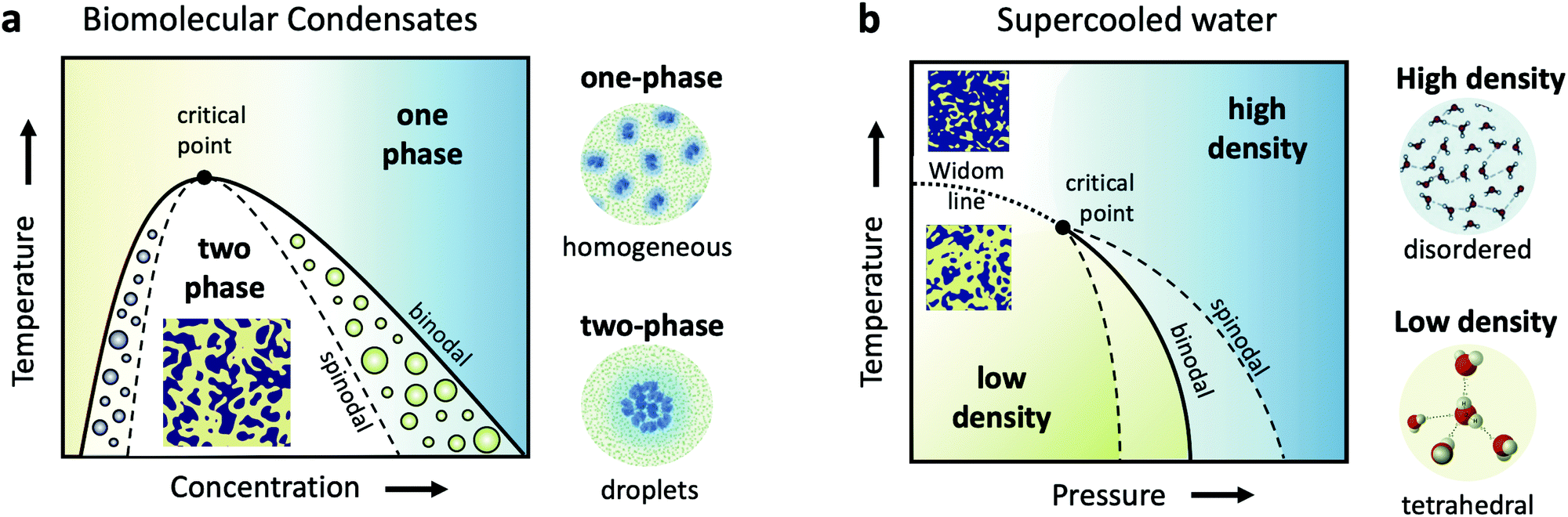 | ||
| Fig. 1 (a) A schematic of the liquid–liquid phase separation (LLPS) in biomolecular condensates, demonstrated in a temperature-concentration phase diagram. The binodal (solid line) is the line separating the one phase region, where proteins are uniformly distributed, and the two-phase region, where they form condensates, resembling liquid droplets. This transition is denoted as LLPS and results in a critical point near which the fluctuations are the strongest. The corresponding spinodal boundary (dashed line) denotes the line where the transition occurs via spinodal decomposition. (b) The hypothesized liquid–liquid critical point of supercooled water shown in a metastable temperature–pressure phase diagram. The binodal denotes the phase coexistence line between the high and low density liquid phases (HDL and LDL). The HDL phase is assumed to be locally disordered contrary to the LDL phase, which features locally tetrahedral coordination. The binodal ends in a critical point, beyond which extends the Widom line (dashed line) and the liquid features a fluctuating mixture of HDL and LDL local regions. | ||
The formed condensates are considered important for concentrating proteins or nucleic acids and facilitating spatiotemporal regulation of cellular function.30 The LLPS may be interrupted by the slow dynamics upon approaching the glass transition line and resulting in an arrested state with a percolating gel network.31 However, so far only a few protein systems have been studied with respect to the kinetics of LLPS and the interplay with glass formation.25,32–35 In addition, very little is known about the dynamics of proteins during the phase transition and upon a deep quench leading to the arrested state,36 as well as aggregate formation (e.g., fibrilles) via protein denaturation.37
Monitoring the dynamics of formation is thus of key importance for advancing our understanding in this field. This in turn requires to resolve an exceptionally large window of time and length scales for which XPCS is ideally suited.
1.2 Supercooled water
Closely related to the dynamics of proteins in the cellular environment is of course the structure and dynamics of water in the cell. Water under such conditions is very different from bulk water, as the solutes can modify significantly the local water environment.38–40 This interplay between water and solvated molecules is termed hydration and is related to many fundamental processes in biophysics, chemical physics, soft matter physics and atmospheric science. However, usually when discussing hydration, water is assumed as a passive homogeneous medium and its heterogeneities as a liquid are mostly ignored.Liquid water is qualitatively different from many other liquids, since for instance water's thermodynamic properties diverge as the liquid is cooled, a behavior often called “anomalous”.41–44 Various thermodynamic scenarios have been proposed to explain these anomalies. One of the scenarios suggests the existence of two phases of liquid water: a high density liquid (HDL) and a low density liquid (LDL),45–47 as depicted in the temperature–pressure phase diagram in Fig. 1b. The HDL liquid is assumed to exhibit a more disordered hydrogen bond network, contrary to the LDL which is assumed to be locally and transiently tetrahedral. The two liquids are hypothesized to be separated by a phase coexistence line, the binodal (solid line) ending in a critical point deeply in the supercooled regime. Simulations indicate that this is indeed the case for many water models,48,49 although it has also been suggested that water can be explained as a single liquid too.50 Even though direct experimental evidence are still not available, there are however increasing experimental indications of the hypothesized critical point, such as the observation of the Widom line in supercooled water,51 which is the extension of the binodal line beyond the critical point (dotted line – Fig. 1b). In this part of the phase diagram, liquid water is depicted as a mixture of fluctuating HDL and LDL-like transient domains, the amount of each population depends on temperature and pressure.
This picture rises important questions such as what is the size and lifetime of these domains? What is the corresponding dynamics of the HDL-like and LDL-like species and what is the HDL–LDL fluctuation time? It has also been extensively debated whether the observed high- and low-density amorphous (HDA and LDA) ice forms are related to two distinct liquid forms through a glass transition.52 Recent dynamic measurements using XPCS indicate that there is a transition between the supercooled HDL and LDL liquids and the corresponding HDA and LDA glassy states in the ultraviscous regime.53 Does this imply that the corresponding dynamics will exhibit a similar behaviour at the high pressure region of the phase diagram?
This deeply supercooled range coincides with a biologically relevant temperature around T = 220 K, termed as the protein dynamic transition.54,55 Below this temperature, many proteins lose their conformational flexibility and biological function. Many studies associate this transition to the intrinsic temperature dependence of the motions of atoms in the protein itself, which experience a cross-over from a harmonic to an anharmonic regime56,57 or cold-denaturation.58,59 Alternatively, it has been proposed that the dynamics are dictated by the hydration water molecules, which is hypothesized to experience a fragile-to-strong transition at this temperature range60 and also coincides with the observation of the Widom line at this temperature range, observed both experimentally in supercooled water,51 and in several water simulations of both pure water48,49 and in protein solutions.61 Is this a coincidence, or does the maximum of water's heterogeneities at biological relevant temperatures signifies causality? Such a connection would directly link properties of supercooled water, which are idiosyncratic and anomalous, to biological function and can fundamentally change the way we view water as a specific requirement for life.
2 X-ray photon correlation spectroscopy
The processes addressed here are often transient in nature and need to be studied en route passing, e.g., through phase transitions or while undergoing spinodal decomposition, as discussed above. In this case the dynamics are evolving during the measurement and considered in quasi equilibrium, i.e., even though the system is speeding up or slowing down it can still be traced by the experiment, while the hierarchical nature of many of the interesting systems requires to cover broad range of timescales and lengthscales. Thus, a technique is needed capable of recording X-ray movies, i.e., which can capture dynamics on logarithmic time scales and identify the heterogeneous dynamics, inherent in the nature of many processes. XPCS is ideally suited for this problem, as it tracks fluctuations in X-ray speckle patterns yielding access to the intermediate scattering function f(Q,t) = S(Q,t)/S(Q,0) by correlating intensities as a function of time and momentum transfer Q.The measured signal in XPCS experiments is the normalized intensity autocorrelation function
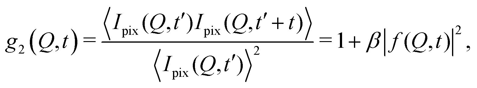 | (1) |
![[thin space (1/6-em)]](https://www.rsc.org/images/entities/char_2009.gif) sin(2θ/2)/λ being the scattering vector, depending on the wavelength λ and the scattering angle 2θ. A schematic of such experiment is shown in Fig. 2. The time delay between two consecutive time frames is denoted t and 〈⋯〉 is the ensemble average over all equivalent delay times t and pixels within a certain range of the absolute value |
sin(2θ/2)/λ being the scattering vector, depending on the wavelength λ and the scattering angle 2θ. A schematic of such experiment is shown in Fig. 2. The time delay between two consecutive time frames is denoted t and 〈⋯〉 is the ensemble average over all equivalent delay times t and pixels within a certain range of the absolute value |![[Q with combining right harpoon above (vector)]](https://www.rsc.org/images/entities/i_char_0051_20d1.gif) |.
|.
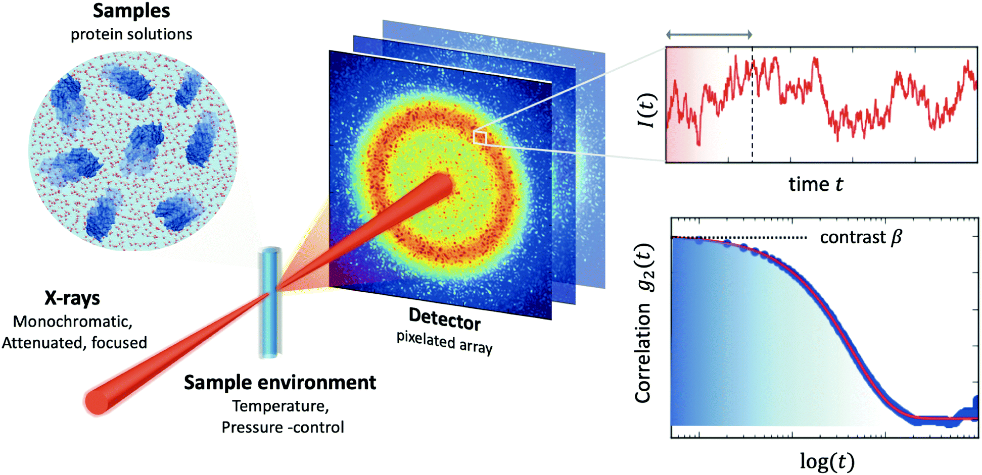 | ||
| Fig. 2 A typical experimental setup of X-ray Photon Correlation Spectroscopy (XPCS) of protein solutions. Coherent X-rays are utilised, which are monochromatic and attenuated, in order to avoid beam induced effects, and focused on the sample. The sample environment usually allows control of an external parameter, such as temperature or pressure. The scattering intensity is recorded with a pixelated 2D array detector. The scattering intensity is recorded as a function of time, which fluctuates due the changes of the speckle pattern (upper right-hand panel). By calculating the intensity correlation function g2 one can obtain information about the dynamics. The amplitude of the correlation function relates to the speckle contrast β and the decay constant reflects the timescale of motion associated with the given momentum transfer Q. | ||
The intermediate scattering function f(Q,t) yields information about collective dynamics and is modelled in an exponential form:
| f(Q,t) = exp[−(Γ(Q)t)α(Q)], | (2) |
An example is shown in Fig. 3a, where we have calculated the intensity autocorrelation function g2(Q,t) for Bovine Serum Albumin (BSA) protein at Q = 0.01 Å−1, assuming simple diffusive dynamics. Being able to measure collective diffusion coefficients D(Q) via Γ(Q) = D(Q)Q2 on molecular length scales is one of the key advantages of XPCS. It is especially important as macromolecular crowding exerts large effects on thermodynamics and kinetic processes64 such as protein stability and enzyme activity. Here, the simultaneous access provided by XPCS to both Γ(Q) and the static density correlation S(Q) yields detailed information about for example electrosteric and solvent-mediated hydrodynamic interactions H(Q).65H(Q) can be accessed via H(Q) = D(Q)S(Q)/D0 with D0 denoting the free diffusion coefficient. Thus, experimental XPCS results can directly be compared to simulation results and help to benchmark properties and importance of, e.g., macromolecular crowding, patchy interactions, dynamic cluster formation.23,25
 | ||
| Fig. 3 The intensity autocorrelation function g2(Q,t) calculated for (a) Bovine Serum Albumin (BSA) protein at Q = 0.01 Å−1. The calculation utilizes the Stokes–Einstein relation and assumes diffusive behaviour and the different curves correspond to increasing protein concentration. By changing the Q range one can effectively probe different length scales of protein dynamics, as depicted in the inset. In this case, the dynamics take place from nanoseconds to microseconds. (b) The g2(Q,t) of liquid and supercooled water estimated from the intermediate scattering function obtained by molecular dynamics.62 Here, the momentum transfer Q = 2.0 Å−1 corresponds to atomic length scales and the correlation decay consists of three separate regimes: the early ballistic motion and the later diffusive regime. Between these two regimes appear cage effects, where molecules experience a transient confinement by their neighbors, which become increasingly pronounced upon supercooling. | ||
2.1 X-ray speckle visibility spectroscopy – measure faster than the detector
The fastest time scales accessible by the movie mode XPCS described above is given by the frame rate of the X-ray camera. While modern X-ray pixelated 2d detectors achieve frame rates of up to MHz,66 faster dynamics are only accessible by using X-ray speckle visibility spectroscopy (XSVS) methods. XSVS measures the contrast (visibility) of an X-ray speckle pattern as a function of exposure time T. Fast dynamics lead to washed out speckle patterns with low contrast, while dynamics slower than the exposure time do not affect the speckle contrast. An example of such rapid dynamics is shown in Fig. 3b, where we display the calculated intensity autocorrelation function g2(Q,t) for liquid and supercooled water, extracted from molecular dynamic simulations.62In XSVS the speckle contrast β thus depends on the exposure time T via67
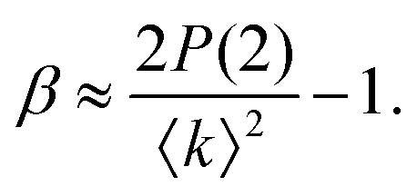
 | (3) |
 | (4) |
Thereby, XSVS can map out dynamics on timescales as fast as 100 fs at XFEL sources.10,62,68–70 In addition, XSVS provides a higher signal-to-noise ratio (SNR) than movie mode XPCS71 and is thus ideally suited to probe dynamics with doses well below 1 kGy. It has been demonstrated that XSVS can be performed with very small count rates of 10−2 to 10−3 photons per pixel,72 given that the response function of the detector is well understood.73,74
Under very low count rate conditions the Poisson-distributed discrete nature of the photon detection process has to be taken into account when analyzing the speckle contrast. Here, the probability P of k photons being registered within one speckle is given by a convolution of the gamma and the Poisson distribution. This results in the negative-binomial distribution also known as Poisson–Gamma distribution,
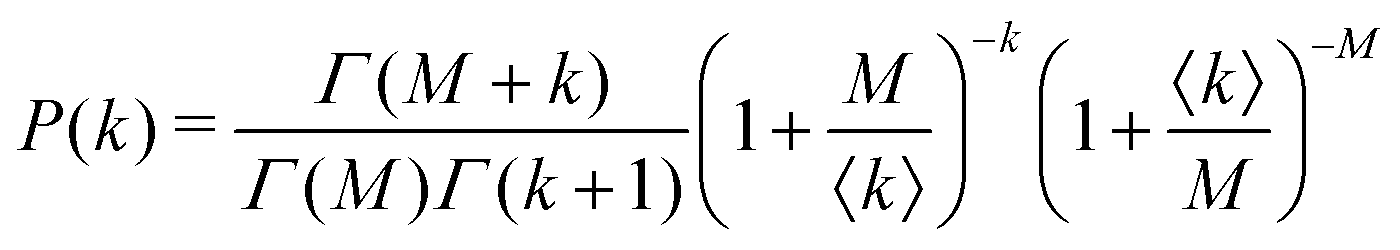 | (5) |
 | (6) |
Thus, we can determine information about Γ(Q) by mapping out the number of 2 photon events for example as a function of XFEL pulse duration or as a function of detector exposure time. This is especially relevant for time scales from femtoseconds to nanoseconds which are too fast to be captured by the frame rate of 2d detectors but which will become accessible by split-and-delay line XPCS at FELs or by inter-pulse correlation at the upgraded MBA storage rings.
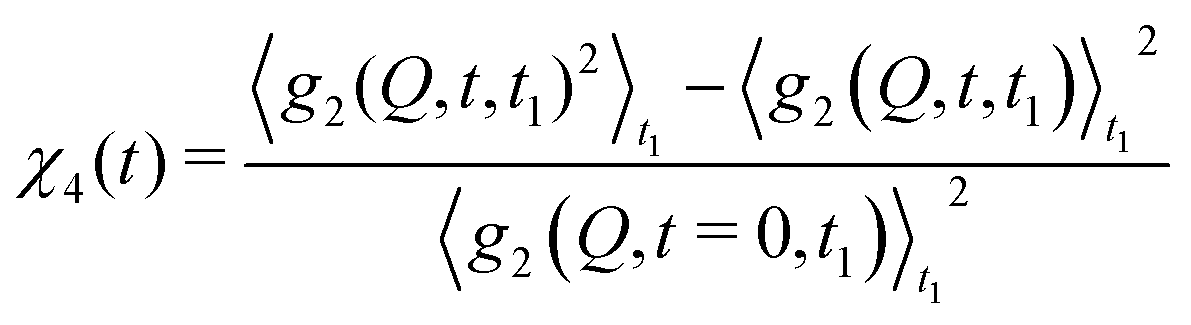
2.2 Higher order correlations – measuring heterogeneous dynamics
With XPCS operating in the time domain we can also investigate dynamically heterogeneous processes via multi-speckle two-time correlation (TTC) functions75,76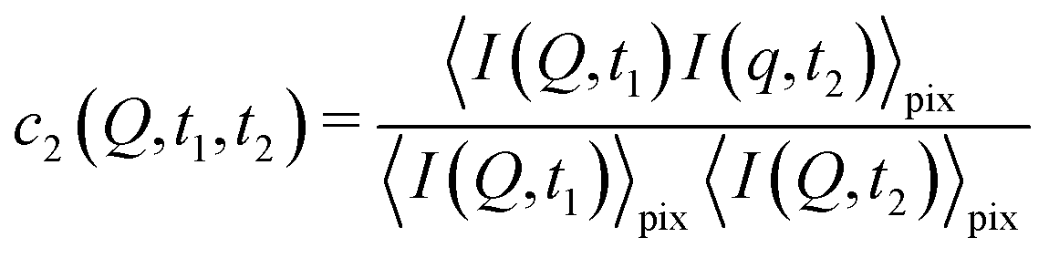 | (7) |
 | (8) |
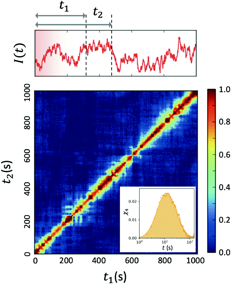 | ||
| Fig. 4 Two-time correlation function c2(Q,t1,t2) of deeply supercooled water originating from high density amorphous (HDA) ice at T = 120 K, which is near the glass transition temperature of HDA. One can see that the dynamics are highly heterogeneous from the fluctuations along the diagonal. The corresponding dynamic susceptibility determined by c2 shown in the inset, which is a quantitative measure of dynamical heterogeneity (adapted with permission from ref. 53). | ||
2.3 The role of new X-ray sources, detectors and big data in XPCS
XPCS requires highly intense coherent X-ray beams. At 3rd generation storage ring (SR) sources only a fraction smaller than 0.5% of the photons in the hard X-ray regime is coherent thus limiting the application of XPCS for studying molecular movies. This limitation is however lifted by the advent of the next generation of storage rings based on the multi-bend-achromat (MBA) lattice technology, already in use by MAXIV and ESRF/EBS and foreseen at APS/U and PETRA IV among others.The new MBA lattices push the brilliance Br of storage rings by 2–3 orders of magnitude leading to an increase of the coherent X-ray flux Fc as given by
 | (9) |
With this increase an up to six orders of magnitude better temporal resolution can be achieved, pushing the temporal window into the regime of microseconds and possibly even faster towards tens of nanoseconds via correlations between single SR pulses. MBA based storage rings also provide smaller source sizes, which allow to use large and coherent beams important for reducing photon density and mitigating beam damage.22
XPCS experiments can also be performed at superconducting XFELs such as the LCLS-II or the European XFEL taking advantage of the MHz repetition rate and the high-pulse brilliance of these sources. By using the split-and-delay technique10,70,81,82 time scales on the order of the pulse duration on the 100 fs scale and below are accessible. In this way XPCS will allow to record movies of molecular motion over a broad range of timescales.
An important prerequisite of XPCS experiments is the availability of fast pixelated X-ray detectors. As the signal to noise ratio (SNR) scales with the speckle contrast small pixels matching the size of the speckles are needed for maximizing the SNR. Typically, these are sizes well below 100 microns. The frame rate needs to be adapted to the time window of interest with the possibility of tracing faster dynamics by speckle visibility techniques. Another important aspect is that for low intensity XPCS the photon statistic needs to be preserved by the detection electronics.73 These are quite high demands on detector technology and additional efforts in detector development are needed to be able to fully exploit the possibility of the new X-ray sources for XPCS.
Recording series of coherent scattering patterns with 4 megapixel and with high frame rates over many days results in very large data sets with sizes easily exceeding tens to hundreds of terabytes. A fast online analysis during the experiment and the in-depth off-line analysis present a challenge due to the shear amount of data.83 Here, advanced analysis schemes such as FPGA based correlators,84 the use of smart data bases including harmonized schemes for meta-data need to be developed as well. Tools such as neural networks and machine learning are promising,85,86 especially for identification of certain events and for model aware analysis of correlation maps. These tools will be of invaluable help for coping with the data avalanche in XPCS.
2.4 Comparison between techniques
Here, we discuss the comparison and complementary aspects of XPCS at synchrotron and XFEL sources with other techniques for measuring structural dynamics, such as neutron techniques.From a time/lengthscale perspective there is a partial overlap of the two techniques. At synchrotron sources, XPCS features a broad range of “slow” dynamics, ranging from microseconds to hours. At XFELs, the accessible timescale of XPCS or XSVS implementations spans from femtoseconds to microseconds, as we discuss in the following sections. On both cases, by changing the momentum transfer, one can probe variable lengthscales ranging from atomic scales to micrometers. In the case of neutron scattering and spectroscopic techniques, such as neutron spin echo and neutron back scattering, the corresponding time window ranges from picoseconds down to hundreds of nanoseconds, whereas the accessible length scales can access from atomic to nanometric scales.
In addition, neutron techniques usually require larger sample volumes than those used at X-ray measurements, due to the larger beam focus size and low neutron scattering cross-section. This limitation poses a challenge for using rapid supercooling techniques, such as the evaporative cooling,51 which require micron-sized droplets. In addition, due to the extremely long scanning time required when using neutrons, it is difficult to follow heterogeneous dynamics in transient samples, such as e.g., the spinodal decomposition during the liquid–liquid phase separation in biomolecular condensates34 or during the liquid–liquid phase transition in ultraviscous water.53 Similar constrains are posed for measuring very slow dynamics, e.g., when examining samples near the glass transition, where dynamics can vary orders of magnitude within a narrow temperature range.
3 Designing XPCS experiments
In this section we discuss the experimental strategies and provide practical tips for designing XPCS experiments. Specifically, we take the example of using XPCS at the European XFEL in order to capture protein dynamics and discuss how to optimize the experimental parameters, mitigate radiation damage and discuss data analysis strategies.3.1 The signal to noise ratio – SNR
XPCS experiments have been termed ‘photon-hungry’ in the past mostly because signal improvement by temporal integration of a measured signal over time is not feasible. Instead, XPCS requires a certain threshold value of scattering intensity per time interval available in the experiments. In turn the signal to noise ratio (SNR) of a correlation function has always been an important quantity for judging temporal and spatial resolution and the overall feasibility of an XPCS experiment.The SNR for the autocorrelation function g2(Q,t) depends on the average intensity per pixel Ipix the speckle contrast β, the number of pixels Npix, the number of frames Nframes and the number of repetitions Nrepvia87,88
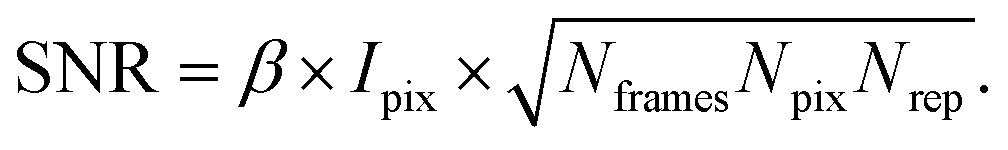 | (10) |
Considering that the number of frames Nframes = T/tfr with tfr being the single-frame exposure time and T being the total accumulated time for Nframes frames, we find in combination with eqn (10) that SNR ∝ Fc × (tfr × T)1/2. This scaling implies that an increase in coherent flux Fc by one order of magnitude gives access to two orders of magnitude faster dynamics for the same SNR.13 For radiation sensitive samples with a maximum tolerable dose one can show that the SNR is modified to SNR ∝ (Fc × tfr × T)1/2 implying that an increase in coherent flux Fc by one order of magnitude gives access to one order of magnitude faster dynamics for the same SNR.22
3.2 Estimating the expected dynamics
A simple way for an educated guess about the expected dynamics is to use the Stokes–Einstein equation: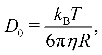 | (11) |
By the relation D(Q) via Γ(Q) = D(Q)Q2 and utilising the eqn (1) and (2), one can derive the expected g2(Q,t) functions for a given momentum transfer Q, as shown in Fig. 3a for the case of Bovine Serum Albumin (BSA) protein, with hydrodynamic radius RH ≈ 3.5 nm.93 The timescales here reflect the capabilities of European XFEL, which due to the MHz repetition rate allows to reach pulse separation down to 220 ns. The viscosity changes depicted can arise from temperature changes, as the viscosity of the solvent can change by more than one order of magnitude upon supercooling, as well as due to increasing protein concentration. In the case of highly concentrated protein solutions, the dynamics can also deviate from the expected Stokes–Einstein behaviour, due to protein–protein interactions and crowding effects, as discussed in the introduction.
A similar estimation can be performed for liquid water (Fig. 3b) on the basis of molecular dynamic simulations.62 In this case the momentum transfer Q relates to atomic lengthscales and the dynamics exhibit distinct regimes: the sub-100 fs timescales relate to ballistic motion, where molecules move nearly independent of each other, followed by cage effects, which become more pronounced upon supercooling. The diffusive dynamics arise on picosecond timescales, as indicated in the schematic. These timecales can be probed with XPCS with the development of the split-and-delay approach,10,70,81,82 where two X-ray pulses are separated by a tunable time delay, which can be varried from a few fs to hundreds of ps.
3.3 Calculating the scattering intensity
The scattering intensity per pixel is a key parameter for XPCS experiments and decisive for deciding on its feasibility. To illustrate this concept we calculate here the scattering intensity per pulse and per pixel as obtained from a pulsed X-ray source, like the European XFEL. The intensity is given by: | (12) |
 the differential cross section and ΔΩpix = (P/L)2 is the solid angle covered by a pixel of size P at a sample-detector distance L. The parameters used here are summarised in Table 1 and were chosen to match typical experimental conditions at the Materials Imaging and Dynamics (MID) instrument of the European XFEL. Here, we set Fc = 108 photons per pulse, in order to minimize any radiation damage effects, discussed in the following section. One can in principle go up to Fc = 3 × 10¹¹ photons per pulse using the pink beam, whereas in the case of using a Si(111) monochromator the flux is estimated to be over Fc ≈ 109 photons per pulse. The pixel size (AGIPD) is P = 200 μm and the sample-detector distance is set at L = 8 m. The sample thickness d = 1 mm corresponds to that of a typical capillary with corresponding transmission Tsample = 0.60155 for water at photon energy E = 10 keV.
| Parameter | Symbol | Value |
|---|---|---|
| Incident flux (attenuated) | F c | 108 photons per pulse |
| Photon energy | E | 10 keV |
| Beam diameter | α | 10 μm |
| Energy resolution | ΔE/E | 10−4 |
| Pixel size | P | 200 μm |
| Sample-detector distance | L | 8 m |
| Sample thickness | d | 1 mm |
| Sample transmission | T sample(E) | 0.60155 |
| BSA absolute intensity | α p | 4.84 m2 kg−1 |
| Concentration | C | 250 mg ml−1 |
| Momentum transfer | Q | 0.01 Å−1 |
| Scattering intensity per pixel | I (Q = 0.01 Å−1) | 0.01 photons per pixel |
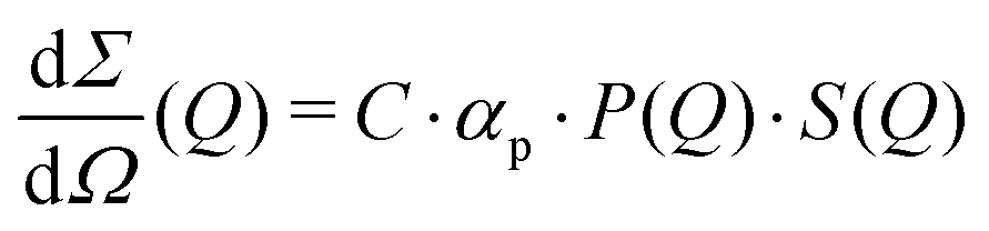
The differential cross section per unit volume is defined as:22
 | (13) |
![[v with combining macron]](https://www.rsc.org/images/entities/i_char_0076_0304.gif) 2·Δρ2 relates to the molar mass M, specific volume and scattering contrast Δρ. The estimation is done for a BSA solution with αp = 4.84 m2 kg−1 (see ref. 94) and concentration C = 250 mg ml−1. A spherical form factor P(Q) = |3·J1(QR)/(QR)|2 was chosen with a radius matching the hydrodynamic radius of BSA, where J1 is the Bessel function of the first kind. The estimation is performed for simplicity in the dilute limit, where the structure factor is unity. A more precise treatment of the protein form and structure factor takes into account the non-spherical shape of the proteins and the intermolecular interaction potential.95 Here, however, for our demonstration purpose this approach suffices and yields an estimate of I(Q) in the order of 0.01 photons per pixel for Q = 0.01 Å−1. Being able to resolve signals with lower photon density than 0.01 photons per pixel (i.e., 1 photon per 100 pixels) is challenging due to experimental reasons73,74 and a detailed level of data analysis and filtering is required in order to clear the signal from parasitic contributions, such as detector noise, photon energy fluctuations and pointing jitter of the source.62,68 However by utilising the combination of new detector technology, high coherence sources and novel data analysis techniques, such as the application of machine learning,85 one can potentially overcome such difficulties and resolve signals with even lower photon density corresponding to atomic length scales. In this case however, it is very important to consider the influence of incident radiation on the sample, as discussed in the following section.
2·Δρ2 relates to the molar mass M, specific volume and scattering contrast Δρ. The estimation is done for a BSA solution with αp = 4.84 m2 kg−1 (see ref. 94) and concentration C = 250 mg ml−1. A spherical form factor P(Q) = |3·J1(QR)/(QR)|2 was chosen with a radius matching the hydrodynamic radius of BSA, where J1 is the Bessel function of the first kind. The estimation is performed for simplicity in the dilute limit, where the structure factor is unity. A more precise treatment of the protein form and structure factor takes into account the non-spherical shape of the proteins and the intermolecular interaction potential.95 Here, however, for our demonstration purpose this approach suffices and yields an estimate of I(Q) in the order of 0.01 photons per pixel for Q = 0.01 Å−1. Being able to resolve signals with lower photon density than 0.01 photons per pixel (i.e., 1 photon per 100 pixels) is challenging due to experimental reasons73,74 and a detailed level of data analysis and filtering is required in order to clear the signal from parasitic contributions, such as detector noise, photon energy fluctuations and pointing jitter of the source.62,68 However by utilising the combination of new detector technology, high coherence sources and novel data analysis techniques, such as the application of machine learning,85 one can potentially overcome such difficulties and resolve signals with even lower photon density corresponding to atomic length scales. In this case however, it is very important to consider the influence of incident radiation on the sample, as discussed in the following section.
3.4 Mitigating and detecting radiation damage
Being able to estimate, detect and mitigate radiation damage is crucial for performing XPCS measurements on biological samples. Previous investigations using Small-Angle X-ray Scattering (SAXS) have studied the radiation limits for different proteins mostly in diluted solutions.96,97 The critical dose Dc is defined as the dose beyond which the radiation starts to degrade the sample and is observed by changes in the SAXS intensity profile and the derived radius of gyration. The typical Dc can vary significantly for different proteins and concentrations, ranging from e.g., ∼0.4 kGy for lysozyme to ∼5 kGy for BSA.96 We should note that the dose limits of proteins in solution are vastly different from those in protein crystallography, where for example lysozyme crystals can withstand up to ∼500 kGy at room temperature98 and up to ∼43 MGy when cryo-cooling is applied.99 The use of reducing agents that can serve as radical scavengers allow to increase the critical dose and the use of cryo-protectants at low concentrations (∼1% m/m), such as glycerol and ethylene glycol, can effectively reduce radiation damage in solutions.97 Furthermore, cryo-cooling can increase the critical dose by at least two orders of magnitude,100 although studying the protein dynamics in glassy water can be very different than those at room temperature. Other approaches for minimizing the dose are related to the sample environment, such as rapid flow and flushing of the sample,101 as well as fast sample scanning techniques.71By carefully designing the experimental parameters one can also optimise the SNR and minimize the dose.22 Here, we provide an educated guess of the dose when using a high repetition X-ray laser, such as the European XFEL, for performing protein XPCS. The absorbed dose D can be calculated via
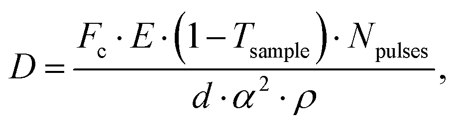 | (14) |
Using the parameters detailed in Table 1 we estimate the dose D as a function of beam size α and number of pulses per bunch train Npulses, as shown in Fig. 5. The upper panel depicts the European XFEL pulse structure, where pulses are separated by 220 ns and are grouped in bunch trains, where each bunch train is separated by 100 ms from the next one. For the MID instrument, a typical number of pulses per bunch can reach up to 350 pulses, which matches the number of pulses that can be read within a single train.66 The lower panel shows the estimated dose, where the dashed lines correspond to typical critical doses of 1 kGy and 10 kGy, respectively. The blue region indicates the low-dose limit (D < Dc), emanating from a larger beamsize and fewer pulses/bunch train, and the red region indicates the high-dose regime (D > Dc). In order to perform XPCS at least two pulses per bunch train are required, with variable spacing between them, so that the g2 function can be composed. The calculation presented in Fig. 5 indicates that for a typical beamsize of α = 10 μm, using 2 pulses would correspond to a dose of ∼0.2 kGy which is below the critical doses discussed above. Furthermore, the use of 10 pulses would correspond to ∼1 kGy and 100 pulses to ∼10 kGy. Lowering the X-ray flux allows to reduce the dose although it becomes increasingly challenging to resolve the speckle pattern for scattering intensities below 0.01 photons per pixel, as discussed in the previous sections. An alternative is to increase the focus size, which however will impact the speckle contrast as discussed in the following section. Finding the optimum SNR for a given critical dose within the experimental parameters is thus an optimization problem which can be solved by algorithms taking all mentioned effects into account.22
 | ||
| Fig. 5 Estimated X-ray dose for a BSA protein solution (250 mg ml−1) as a function of beam size and number of pulses per bunch train. The upper panel shows the European XFEL pulse sequence, where the pulses have a minimum separation of 220 ns and the bunch trains are separated by 100 ms. The lower panel shows the dose estimate for a standard configuration at the MID instrument of Eu-XFEL, where a typical critical doses of protein solutions of 1 kGy to 10 kGy are denoted with dashed lines. | ||
One of the most established approaches in order to detect radiation damage is to measure the SAXS lineshape as a function of photon flux and deduce radiation damage from changes in the protein radius of gyration.96 For XPCS measurements it is important to, in addition, investigate whether the X-ray beam influences the underlying dynamics. At synchrotron sources, one can achieve this task by measuring the g2 function for different photon fluxes and in this way find the regime where the dynamics become independent of the flux.53 At XFELs one can take a similar approach and sort and bin the detected scattering patterns as a function of the XFEL intensity.62 In addition, it is very helpful to have a second detector so that one can record the wide-angle X-ray scattering (WAXS), which again can allow to deduce any changes in the scattering intensity as a function of flux, in addition to the dynamic information.53,62 Finally, being able to capture the two-time correlation function can also allow for insight into potential beam induced effects, as seen previously in oxide glasses.102
3.5 Speckle contrast
One important aspect of designing XPCS experiments is the speckle contrast. Being able to resolve clearly a speckle pattern is crucial for the success of the experiment, although it often works against other important parameters, such as having sufficient scattering intensity per pixel and limiting the dose, discussed in the previous sections. As such, being able to analytically predict the speckle contrast can help us balance the aforementioned contributions to the experimental signal-to-noise ratio. The mathematical formalism for calculation of β has been previously presented in detail in ref. 22.We calculate the speckle contrast β for the parameters listed in Table 1, as shown in Fig. 6. The solid line depicts β as a function of momentum transfer Q for the experimental arrangement where a Si(111) monochromator is used, whereas the dashed line corresponds to the β obtained with a “pink beam”. The corresponding relative photon energy bandwidth ΔE/E is depicted in the figure caption, whereas the schematic above the figure shows speckle patterns for three characteristic contrast values. Despite the relatively rapid decrease of contrast, our estimation indicates that such experiments would benefit by using a monochromator in order to resolve the dynamics at higher momentum transfer Q, whereas further improvement can be implemented by using the XFEL in seeding mode.103
 | ||
| Fig. 6 Estimated speckle contrast β as a function of momentum transfer Q. The upper panel is schematic of the speckle pattern for different contrast values. We estimate β for two different conditions: using a Si(111) monochromator, which yields a relative energy bandwidth ΔE/E = 1.4 × 10⁻⁴ (solid blue line) and using pink beam with ΔE/E = 10−3 (red dashed line). The calculation is again done for BSA protein solution using a standard configuration at the MID instrument of Eu-XFEL (see text). | ||
4 Conclusions
Many molecular systems display dynamics over a large hierarchy of length and time scales with the dynamics being often heterogeneous and/or transient in nature. Measuring dynamics from microns to nanometers and from femtoseconds to minutes has been a challenge for most experimental techniques up to now. The revolution in X-ray sources we witness right now in combination with the development of fast and pixelated area detectors promises that the molecular movie will become reality. XPCS could unravel the details of protein dynamics in crowded environments and during phase transitions. XPCS provides the exciting possibility of time-resolved imaging of functionally relevant processes such as aggregation (important in neurodegenerative disease), phase separations and partitioning (important for example in development and infection), and self-assembly (important in the development of tissues and organs, virus infections and the formation of bio-inspired materials). This would allow the study of crowded and dynamic biological systems and provide extremely novel fundamental data describing inter-protein interactions in the concentrated regime. This information would have a huge impact on specific questions, such as understanding how misfolding leads to aggregation and disease in pathologies such as prion disease or Alzheimer's.Furthermore, understanding supercooling and vitrification mechanisms of biological solutions is crucial for improving cryopreservation techniques used in medical applications. This is a key step in the storage of frozen organs and cells used in cancer research or in the cryopreservation of microorganisms, such as viruses and bacteria. When performed successfully, rapid quenching will lead to the formation of a perfect glass, free from crystal impurities that can damage the biological content. Even though the majority of studies have so far focused on optimising vitrification based on structural probes, such as transmission electron microscopy or X-ray diffraction techniques, the dynamical aspects are still largely unexplored. With XPCS we can gain new insight into the dynamics of supercooled water and protein solutions.
With several experimental stations being operational or being built in the coming years we expect that XPCS will contribute substantially to addressing open questions in molecular systems. Especially, making XPCS data FAIR104 and openly available will advance the field tremendously by enabling experimental reproducibility and by allowing direct comparison to simulations. Such a step can facilitate the implementation of more sophisticated modeling and data analysis algorithms based on machine learning methods85,86 which will become invaluable in the future in order to cope with rapidly increasing data rates and increasing experimental complexity.
Conflicts of interest
There are no conflicts to declare.Acknowledgements
We would like to thank Anders Nilsson and Mario Reiser for their useful comments on the manuscript. FP acknowledges financial support by the Swedish National Research Council (Vetenskapsrådet) under Grant No. 2019-05542 and within the Röntgen-Ångström Cluster Grant No. 2019-06075. CG acknowledges support from BMBF via projects 05K19PS1 and Röntgen-Ångström Cluster Grant 05K20PSA.Notes and references
- D. Einfeld, J. Schaper and M. Plesko, J. Phys. IV France, 1994, 4, C9-373–C9-376 CrossRef.
- D. Einfeld, M. Plesko and J. Schaper, J. Synchrotron Radiat., 2014, 21, 856–861 CrossRef CAS PubMed.
- P. F. Tavares, S. C. Leemann, M. Sjöström and A. Andersson, J. Synchrotron Radiat., 2014, 21, 862–877 CrossRef CAS PubMed.
- P. Raimondi, Synchrotron Radiat., 2016, 29, 8–15 CrossRef.
- F. Stephan, et al. , Phys. Rev. ST Accel. Beams, 2010, 13, 020704 CrossRef.
- C. Bostedt, et al. , J. Phys. B: At., Mol. Opt. Phys., 2013, 46, 164003 CrossRef.
- W. Decking, et al. , Nat. Photonics, 2020, 14, 391–397 CrossRef CAS.
- M. Dunne and R. W. Schoenlein, X-ray Free Electron Lasers, Springer, 2018, pp. 441–466 Search PubMed.
- G. Grübel and F. Zontone, J. Alloys Compd., 2004, 362, 3–11 CrossRef.
- C. Gutt, L.-M. Stadler, A. Duri, T. Autenrieth, O. Leupold, Y. Chushkin and G. Grübel, Opt. Express, 2009, 17, 55–61 CrossRef CAS PubMed.
- G. Grübel, A. Madsen and A. Robert, in Soft Matter Characterization, ed. R. Borsali and R. Pecora, Springer, Netherlands, 2008, pp. 953–995 Search PubMed.
- G. B. Stephenson, A. Robert and G. Grübel, Nat. Mater., 2009, 8, 702–703 CrossRef CAS PubMed.
- O. G. Shpyrko, J. Synchrotron Radiat., 2014, 21, 1057–1064 CrossRef CAS PubMed.
- A. Madsen, A. Fluerasu and B. Ruta, inSynchrotron Light Sources and Free-Electron Lasers, ed. E. J. Jaeschke, S. Khan, J. R. Schneider and J. B. Hastings, Springer International Publishing, 2016, pp. 1617–1641 Search PubMed.
- A. R. Sandy, Q. Zhang and L. B. Lurio, Annu. Rev. Mater. Res., 2018, 48, 167–190 CrossRef CAS.
- R. L. Leheny, Curr. Opin. Colloid Interface Sci., 2012, 17, 3–12 CrossRef CAS.
- M. Leitner, B. Sepiol, L.-M. Stadler, B. Pfau and G. Vogl, Nat. Mater., 2009, 8, 717–720 CrossRef CAS PubMed.
- B. Ruta, et al. , Phys. Rev. Lett., 2012, 109, 165701 CrossRef CAS PubMed.
- S. K. Sinha, Z. Jiang and L. B. Lurio, Adv. Mater., 2014, 26, 7764–7785 CrossRef CAS PubMed.
- R. M. Karl Jr, et al. , Phys. Chem. Chem. Phys., 2015, 17, 16682–16687 RSC.
- P. Vodnala, et al. , Phys. Rev. E, 2018, 97, 020601 CrossRef CAS PubMed.
- J. Möller, M. Sprung, A. Madsen and C. Gutt, IUCrJ, 2019, 6, 794–803 CrossRef PubMed.
- A. Stradner and P. Schurtenberger, Soft Matter, 2020, 16, 307–323 RSC.
- N. Skar-Gislinge, et al. , Mol. Pharmaceutics, 2019, 16, 2394–2404 CrossRef CAS PubMed.
- S. Bucciarelli, et al. , Sci. Adv., 2016, 2, e1601432 CrossRef PubMed.
- J. S. Myung, F. Roosen-Runge, R. G. Winkler, G. Gompper, P. Schurtenberger and A. Stradner, J. Phys. Chem. B, 2018, 122, 12396–12402 CrossRef CAS PubMed.
- L. Tang, Nat. Methods, 2019, 16, 456 CrossRef CAS PubMed.
- C. P. Brangwynne, et al. , Science, 2009, 324, 1729–1732 CrossRef CAS PubMed.
- A. Ianiro, et al. , Nat. Chem., 2019, 11, 320–328 CrossRef CAS PubMed.
- S. Alberti and D. Dormann, Annu. Rev. Genet., 2019, 53, 112618 CrossRef PubMed.
- E. Zaccarelli, J. Phys.: Condens. Matter, 2007, 19, 323101 CrossRef.
- T. Gibaud and P. Schurtenberger, J. Phys.: Condens. Matter, 2009, 21, 322201 CrossRef PubMed.
- F. Cardinaux, T. Gibaud, A. Stradner and P. Schurtenberger, Phys. Rev. Lett., 2007, 99, 118301 CrossRef PubMed.
- S. Da Vela, M. K. Braun, A. Dörr, A. Greco, J. Möller, Z. Fu, F. Zhang and F. Schreiber, Soft Matter, 2016, 12, 9334–9341 RSC.
- F. Zhang, J. Phys.: Condens. Matter, 2017, 29, 443002 CrossRef PubMed.
- M. Grimaldo, F. Roosen-Runge, F. Zhang, F. Schreiber and T. Seydel, Q. Rev. Biophys., 2019, 52, e7 CrossRef.
- M. Carballo-Pacheco and B. Strodel, J. Phys. Chem. B, 2016, 120, 2991–2999 CrossRef CAS PubMed.
- M. Chaplin, Nat. Rev. Mol. Cell Biol., 2006, 7, 861–866 CrossRef CAS PubMed.
- P. Ball, Chem. Rev., 2008, 108, 74–108 CrossRef CAS PubMed.
- P. Ball, Proc. Natl. Acad. Sci. U. S. A., 2017, 114, 13327–13335 CrossRef CAS PubMed.
- C. A. Angell, Annu. Rev. Phys. Chem., 1983, 34, 593–630 CrossRef CAS.
- P. G. Debenedetti and H. E. Stanley, Phys. Today, 2007, 56, 40 CrossRef.
- A. Nilsson and L. G. M. Pettersson, Nat. Commun., 2015, 6, 1–11 Search PubMed.
- J. Swenson, Phys. Chem. Chem. Phys., 2018, 20, 30095–30103 RSC.
- P. H. Poole, F. Sciortino, U. Essmann and H. E. Stanley, Nature, 1992, 360, 324–328 CrossRef CAS.
- C. A. Angell, Nat. Mater., 2014, 13, 673–675 CrossRef CAS PubMed.
- P. Gallo, et al. , Chem. Rev., 2016, 116, 7463–7500 CrossRef CAS PubMed.
- J. C. Palmer, F. Martelli, Y. Liu, R. Car, A. Z. Panagiotopoulos and P. G. Debenedetti, Nature, 2014, 510, 385–388 CrossRef CAS PubMed.
- P. G. Debenedetti, F. Sciortino and G. H. Zerze, Science, 2020, 369, 289–292 CAS.
- A. K. Soper, J. Chem. Phys., 2019, 150, 234503 CrossRef CAS PubMed.
- K. H. Kim, et al. , Science, 2017, 358, 1589–1593 CrossRef CAS PubMed.
- O. Mishima and H. E. Stanley, Nature, 1998, 396, 329–335 CrossRef CAS.
- F. Perakis, et al. , Proc. Natl. Acad. Sci. U. S. A., 2017, 114, 8193–8198 CrossRef CAS PubMed.
- W. Doster, S. Cusack and W. Petry, Nature, 1989, 337, 754 CrossRef CAS PubMed.
- B. F. Rasmussen, A. M. Stock, D. Ringe and G. A. Petsko, Nature, 1992, 357, 423 CrossRef CAS PubMed.
- R. M. Daniel, J. C. Smith, M. Ferrand, S. Héry, R. Dunn and J. L. Finney, Biophys. J., 1998, 75, 2504–2507 CrossRef CAS PubMed.
- M. Tarek and D. J. Tobias, Phys. Rev. Lett., 2002, 88, 138101 CrossRef CAS PubMed.
- C. Yang, S. Jang and Y. Pak, Nat. Commun., 2014, 5, 5773 CrossRef CAS PubMed.
- S. B. Kim, J. C. Palmer and P. G. Debenedetti, Proc. Natl. Acad. Sci. U. S. A., 2016, 113, 8991–8996 CrossRef CAS PubMed.
- S.-H. Chen, L. Liu, E. Fratini, P. Baglioni, A. Faraone and E. Mamontov, Proc. Natl. Acad. Sci. U. S. A., 2006, 103, 9012–9016 CrossRef CAS PubMed.
- P. Kumar, et al. , Phys. Rev. Lett., 2006, 97, 177802 CrossRef PubMed.
- F. Perakis, et al. , Nat. Commun., 2018, 9, 1–10 CrossRef CAS PubMed.
- G. Williams and D. C. Watts, Trans. Faraday Soc., 1970, 66, 80–85 RSC.
- T. Ando and J. Skolnick, Proc. Natl. Acad. Sci. U. S. A., 2010, 107, 18457–18462 CrossRef CAS PubMed.
- A. J. Banchio, et al. , Phys. Rev. Lett., 2006, 96, 138303 CrossRef PubMed.
- A. Allahgholi, et al. , Nucl. Instrum. Methods Phys. Res., Sect. A, 2019, 942, 162324 CrossRef CAS.
- R. Bandyopadhyay, A. Gittings, S. Suh, P. Dixon and D. J. Durian, Rev. Sci. Instrum., 2005, 76, 093110 CrossRef.
- S. Hruszkewycz, et al. , Phys. Rev. Lett., 2012, 109, 185502 CrossRef CAS PubMed.
- M. Seaberg, et al. , Phys. Rev. Lett., 2017, 119, 067403 CrossRef CAS PubMed.
- W. Roseker, et al. , Nat. Commun., 2018, 9, 1704 CrossRef CAS PubMed.
- J. Verwohlt, M. Reiser, L. Randolph, A. Matic, L. A. Medina, A. Madsen, M. Sprung, A. Zozulya and C. Gutt, Phys. Rev. Lett., 2018, 120, 168001 CrossRef CAS PubMed.
- C. DeCaro, et al. , J. Synchrotron Radiat., 2013, 20, 332–338 CrossRef CAS PubMed.
- J. Möller, et al. , J. Synchrotron Radiat., 2019, 26, 1705–1715 CrossRef PubMed.
- Y. Sun, J. Montana-Lopez, P. Fuoss, M. Sutton and D. Zhu, J. Synchrotron Radiat., 2020, 27, 999–1007 CrossRef.
- A. Malik, A. Sandy, L. Lurio, G. Stephenson, S. Mochrie, I. McNulty and M. Sutton, Phys. Rev. Lett., 1998, 81, 5832 CrossRef CAS.
- A. Madsen, R. L. Leheny, H. Guo, M. Sprung and O. Czakkel, New J. Phys., 2010, 12, 055001 CrossRef.
- S. Gorfman, et al. , Proc. Natl. Acad. Sci. U. S. A., 2018, 115, E6680–E6689 CrossRef CAS PubMed.
- G. Ju, D. Xu, M. J. Highland, C. Thompson, H. Zhou, J. A. Eastman, P. H. Fuoss, P. Zapol, H. Kim and G. B. Stephenson, Nat. Phys., 2019, 15, 589–594 Search PubMed.
- A. Ricci, et al. , Phys. Rev. B: Condens. Matter Mater. Phys., 2020, 101, 020508 CrossRef CAS.
- L. Berthier, Physics, 2011, 4, 42 CrossRef.
- W. Roseker, H. Franz, H. Schulte-Schrepping, A. Ehnes, O. Leupold, F. Zontone, A. Robert and G. Grübel, Opt. Lett., 2009, 34, 1768–1770 CrossRef CAS PubMed.
- T. Osaka, et al. , Opt. Express, 2016, 24, 9187–9201 CrossRef CAS PubMed.
- F. Khan, S. Narayanan, R. Sersted, N. Schwarz and A. Sandy, J. Synchrotron Radiat., 2018, 25, 1135–1143 CrossRef PubMed.
- J. Buchholz, J. W. Krieger, G. Mocsár, B. Kreith, E. Charbon, G. Vámosi, U. Kebschull and J. Langowski, Opt. Express, 2012, 20, 17767–17782 CrossRef PubMed.
- A. Sanchez-Gonzalez, et al. , Nat. Commun., 2017, 8, 1–9 CrossRef PubMed.
- H. He, C. Liu and H. Liu, iScience, 2020, 23, 100906 CrossRef CAS PubMed.
- P. Falus, L. B. Lurio and S. G. J. Mochrie, J. Synchrotron Radiat., 2006, 13, 253–259 CrossRef CAS PubMed.
- D. Lumma, L. Lurio, S. Mochrie and M. Sutton, Rev. Sci. Instrum., 2000, 71, 3274–3289 CrossRef CAS.
- A. Dehaoui, B. Issenmann and F. Caupin, Proc. Natl. Acad. Sci. U. S. A., 2015, 112, 12020–12025 CrossRef CAS PubMed.
- T. Kawasaki and K. Kim, Sci. Adv., 2017, 3, e1700399 CrossRef PubMed.
- E. Guillaud, S. Merabia, D. de Ligny and L. Joly, Phys. Chem. Chem. Phys., 2017, 19, 2124–2130 RSC.
- R. Shi, J. Russo and H. Tanaka, Proc. Natl. Acad. Sci. U. S. A., 2018, 115, 9444–9449 CrossRef CAS PubMed.
- F. Roosen-Runge, M. Hennig, F. Zhang, R. M. J. Jacobs, M. Sztucki, H. Schober, T. Seydel and F. Schreiber, Proc. Natl. Acad. Sci. U. S. A., 2011, 108, 11815–11820 CrossRef CAS PubMed.
- E. Mylonas and D. I. Svergun, J. Appl. Crystallogr., 2007, 40, s245–s249 CrossRef CAS.
- J. Möller, et al. , Biophys. J., 2012, 102, 2641–2648 CrossRef PubMed.
- C. M. Jeffries, M. A. Graewert, D. I. Svergun and C. E. Blanchet, J. Synchrotron Radiat., 2015, 22, 273–279 CrossRef CAS PubMed.
- S. Kuwamoto, S. Akiyama and T. Fujisawa, J. Synchrotron Radiat., 2004, 11, 462–468 CrossRef CAS PubMed.
- R. J. Southworth-Davies, M. A. Medina, I. Carmichael and E. F. Garman, Structure, 2007, 15, 1531–1541 CrossRef CAS PubMed.
- R. L. Owen, E. Rudiño-Piñera and E. F. Garman, Proc. Natl. Acad. Sci. U. S. A., 2006, 103, 4912–4917 CrossRef CAS PubMed.
- S. P. Meisburger, et al. , Biophys. J., 2013, 104, 227–236 CrossRef CAS PubMed.
- N. Kirby, et al. , Acta Crystallogr., Sect. D: Struct. Biol., 2016, 72, 1254–1266 CrossRef CAS PubMed.
- B. Ruta, F. Zontone, Y. Chushkin, G. Baldi, G. Pintori, G. Monaco, B. Ruffle and W. Kob, Sci. Rep., 2017, 7, 1–8 CrossRef CAS PubMed.
- J. Amann, et al. , Nat. Photonics, 2012, 6, 693–698 CrossRef CAS.
- M. D. Wilkinson, et al. , Sci. Data, 2016, 3, 160018 CrossRef PubMed.
| This journal is © the Owner Societies 2020 |