 Open Access Article
Carbon dioxide and water incorporation mechanisms in SrFeO3−δ phases: a computational study
L. J.
Ford
a,
P. R.
Slater
 b,
J. K.
Christie
 *a and
P.
Goddard
 *c
*c
aDepartment of Materials, Loughborough University, Epinal Way, Loughborough, Leicestershire LE11 3TU, UK. E-mail: J.K.Christie@lboro.ac.uk
bSchool of Chemistry, University of Birmingham, Edgbaston, Birmingham, B15 2TT, UK
cDepartment of Chemistry, Loughborough University, Epinal Way, Loughborough, Leicestershire LE11 3TU, UK. E-mail: P.Goddard@lboro.ac.uk
First published on 14th October 2020
Abstract
With a higher propensity for low temperature synthesis routes along with a move toward lower solid oxide fuel cell operating temperatures, water and carbon dioxide incorporation in strontium ferrite is of importance. Despite this, the mechanisms are not well understood. In this work, classical-potential-based computational techniques are used to determine the favourability of water and CO2 incorporation mechanisms in both SrFeO3−δ and SrFeO2.5. Our studies suggest that intrinsic Frenkel and Schottky type defects are unlikely to form, but that water and carbon dioxide incorporation are favourable in both phases. Water incorporation is likely for both the cubic and brownmillerite phases, with hydroxyl ions preferring to sit on octahedral oxygen sites in both structures, causing slight tilting of the shared octahedra. Interstitial hydroxyl ions are only likely for the brownmillerite phase, where the hydroxyl ions are most stable between adjacent FeO4 tetrahedral chains. Carbon dioxide incorporation via carbonate defects is most favourable when a carbonate molecule exists on an iron site, preferring the iron site with lower oxygen coordination. This involves formation of multiple oxygen vacancies surrounding the iron site, and thus we conclude that carbonate can trap oxygen vacancies.
1 Introduction
Solid oxide fuel cells (SOFCs) are likely to play an important role in the future of the world's sustainable energy system. Perovskite-based materials are among the most popular choice for SOFC electrode and electrolyte components as they often exhibit good conductive properties, stability and versatility. There are a large number of perovskite candidates,1,2 one of which is SrFeO3−δ, which in its cubic phase exhibits high electronic and ionic conductivity and therefore has been identified as a promising cathode material.3,4 At SOFC operating temperatures and with low oxygen content, strontium ferrite exists as brownmillerite-type SrFeO2.5, which has lower conductivity than the cubic system due to oxygen vacancy ordering and therefore is currently less suitable for SOFC application. However, under doping, oxygen vacancy ordering can be lowered; other brownmillerite structures such as Ba2In2O55 and HSrCoO2.56 have shown promise regarding conductivity with oxyanion doping strategies for low- to intermediate-temperature SOFC applications.At room temperature, strontium ferrite can exist in a number of different structures dependent on the oxygen content. The phases are cubic (SrFeO3), tetragonal (SrFeO2.875), orthorhombic (SrFeO2.75) and brownmillerite-type (SrFeO2.5). Cubic SrFeO3 contains Fe4+ ions on the B site, each with an oxygen coordination of six, forming corner-sharing FeO6 octahedra. In reality, pure SrFeO3 is difficult to synthesise requiring high oxygen pressure. The brownmillerite-type SrFeO2.5 structure contains only Fe3+ ions, and oxygen vacancy ordering results in alternate layers of Fe–O6 octahedra and Fe–O4 tetrahedra.7 At temperatures above 850 °C, SrFeO2.5 becomes cubic, but with a larger unit cell than the room temperature SrFeO3 cubic perovskite.8 The orthorhombic SrFeO2.75 and tetragonal SrFeO2.875 phases contain variable iron charges between 3+ and 4+. A recent DFT study on SrFeO3−δ by Das et al. has elucidated the charge states of iron in these oxygen-vacancy-ordered phases, finding that the charge on Fe in square-pyramidal FeO5 coordination remains 4+ and the charge on Fe in the FeO6 octahedra varies between 4+ to 3+ due to the different d-orbital splitting of square-pyramidal and octahedral iron.9
To ensure high ionic conductivity in SrFeO3−δ, disordered oxygen vacancies must be present, avoiding the phase transition to a phase with ordered oxygen vacancies. Doping is a common strategy for inducing oxygen vacancies and modifying structure. Recent experimental work3,4,10 has shown that oxyanion doping in perovskites can lead to favourable conductivity and structural effects. A study of Si incorporation into SrFeO3−δ showed that Si4+ incorporation on the B site suppresses the formation of brownmillerite-type structures by forming SiO4 tetrahedra which trap oxygen vacancies.11 Interatomic-potential-based computational calculations allowed the structural and energetic details of the mechanisms in this work to be better understood.
In an operating fuel cell air electrode, both CO2 and H2O will likely be present, and it is useful therefore to look at their behaviour and mechanisms of their incorporation within SOFC component materials to discover their effect on structure and conductivity. McSloy et al. have used classical-potential-based computational methodology to look at carbon dioxide and water incorporation mechanisms and oxygen trapping in A2BO4 systems,12,13 and found that carbonate defects are likely to be common impurities which trap oxygen ion defects. In some materials, water incorporation can lead to structural changes which alter the level of proton or oxygen–ion conduction. This increase in conductivity makes application for SOFCs more valuable both for use with an oxide ion or proton conducting electrolyte, and therefore water incorporation is worth investigating.
There are several reasons why looking at carbon dioxide incorporation is of interest in SrFeO3. Carbon dioxide is present in air, and so consequently is present at the cathode of an SOFC and thus will inevitably interact with the cathode structure. In low- to intermediate-temperature SOFCs, carbonate may be thermally stable enough in the structure to consider incorporation likely, with potentially significant degradation or conductivity in the cathode material. In this paper, therefore, we present classical-potential-based computational work modelling H2O and CO2 incorporation into cubic SrFeO3−δ and brownmillerite-type SrFeO2.5 to look at the mechanisms of their inclusion using energy minimisation techniques.
2 Methodology
Interatomic-potential-based energy minimisation calculations were performed using the General Utility Lattice Program (GULP)14,15 and structural images rendered using Visualisation for Electronic and STructural Analysis (VESTA).16 Interatomic energies were based on the Born model for ionic solids where long- and short-range pairwise terms are used to describe the Coulombic, and the Pauli repulsive and van der Waals interactions, respectively. In this work, short-range ionic interactions were modelled using the Buckingham potential:17 | (1) |
Ionic polarisability is something which must also be accounted for in defective solid structure calculations: to model this we used the shell model developed by Dick and Overhauser,18 which splits atoms into a separate charged core and shell connected by a spring force.
To find reliable potentials, existing Buckingham potential parameters from the literature19–21 were used and tested on various strontium ferrite systems, and parameters were then fitted to the experimental structures of cubic SrFeO3, tetragonal SrFeO2.875, orthorhombic SrFeO2.75 and brownmillerite like SrFeO2.5, such that the potentials fitted were transferable to all structures. The Buckingham potential parameters used for the entirety of this work can be found in Table 1. The optimised structural geometries compared to experimental structures are shown in Table 2. The respective binary oxides SrO and Fe2O3 were also fitted to, in order to validate the potentials and ensure a good degree of transferability.
| Interaction | A/eV | ρ/Å | C/eV Å6 |
|---|---|---|---|
| (a) Buckingham potentials | |||
| Sr2+–O2− | 1323.895825 | 0.34 | 0 |
| Fe4+–O2− | 1540 | 0.3249 | 0 |
| Fe3+–O2− | 1156.36 | 0.3249 | 0 |
| O2−–O2− | 22764.3 | 0.149 | 43 |
| O2−–H | 311.97 | 0.25 | 0 |
| O2−–C | 435.0 | 0.34 | 0 |
| OC–OC | 4030.3 | 0.2455 | 0 |
| Interaction | D/eV | β/Å−1 | r 0/Å |
|---|---|---|---|
| (b) Morse potentials | |||
| Oh–H | 7.0525 | 2.1986 | 0.94850 |
| OC–C | 5.0000 | 2.5155 | 1.20246 |
| Interaction | k 2/eV rad−2 | θ 0/° |
|---|---|---|
| (c) Three body potential | ||
| OC–OC–C | 1.7887 | 120 |
| Interaction | k/eV | θ 0/° |
|---|---|---|
| (d) Torsional term | ||
| OC–OC–C–OC | 1.10 | 0.0 |
| Species | k 2/eV Å2 | k 4/eV Å4 |
|---|---|---|
| (e) Spring interactions | ||
| OC | 20.67 | 1000 |
| O2− | 42 | — |
| Sr2+ | 21.53 | — |
| Fe3+ and Fe4+ | 304.7 | — |
| Species | Shell/e | Core/e |
|---|---|---|
| (f) Shell model charges | ||
| O2− | −2.389 | 0.389 |
| Sr | 1.33 | 0.67 |
| Fe3+ | −1.97 | 4.97 |
| Fe4+ | −1.97 | 5.97 |
| H | — | 0.426 |
| Oh | — | −1.426 |
| C | — | 1.45 |
| OC | 0.23 | −1.38 |
| Parameter | Exptl29 | Calc. | % Diff. |
|---|---|---|---|
(a) SrFeO3, space group Pm![[3 with combining macron]](https://www.rsc.org/images/entities/char_0033_0304.gif) m (221) m (221) |
|||
| a/Å | 3.851 | 3.828 | −0.60 |
| α = β = γ (°) | 90 | 90 | |
| Parameter | Exptl29 | Calc. | % Diff. |
|---|---|---|---|
| (b) SrFeO2.875, space group I4/mmm (139) | |||
| a/Å | 10.929 | 10.797 | −1.21 |
| c/Å | 7.698 | 7.671 | −0.34 |
| α = β = γ (°) | 90 | 90 | |
| Parameter | Exptl29 | Calc. | % Diff. |
|---|---|---|---|
| (c) SrFeO2.75, space group Cmmm (65) | |||
| a/Å | 10.974 | 10.895 | −0.72 |
| b/Å | 7.702 | 7.688 | −0.17 |
| c/Å | 5.473 | 5.446 | −0.49 |
| α = β = γ (°) | 90 | 90 | |
| Parameter | Exptl30 | Calc. | % Diff. |
|---|---|---|---|
| (d) SrFeO2.5, space group Ima2 (46) | |||
| a/Å | 15.598 | 14.851 | −4.79 |
| b/Å | 5.661 | 5.628 | −0.58 |
| c/Å | 5.531 | 5.491 | −0.72 |
| α = β = γ (°) | 90 | 90 | |
| Parameter | Exptl26 | Calc. | % Diff. |
|---|---|---|---|
| (e) Sr4Fe2O6(CO3), space group I4/mmm (139) | |||
| a/Å | 3.878 | 3.831 | −1.2 |
| c/Å | 27.982 | 27.846 | −0.50 |
| α = β = γ (°) | 90 | 90 | |
| Parameter | Exptl27 | Calc. | % Diff. |
|---|---|---|---|
| (f) Sr3Fe2(OH)12, space group Ia3d (230) | |||
| a/Å | 13.202 | 13.443 | 3.16 |
| α = β = γ (°) | 90 | 90 | |
For intramolecular interactions between O–H and C–O in the water and carbon dioxide incorporation calculations respectively, interactions were described with a Morse potential22 as it better describes the covalent character of the bond:
| ϕij(r) = De[(1 − exp(−a(1 − r0)))2 − 1] | (2) |
For the carbon dioxide incorporation calculations, a three-body potential was used to energetically penalise deviation from the desired 120° of the carbonate group. This potential was of the form:
 | (3) |
A torsional term was also included for the carbonate anion, to penalise it from deviating from the preferred flat configuration, this is of the form:
| ϕijkl(θijkl) = k4(1 − cos(nθijkl − θ0)) | (4) |
The charges and potential parameter values for oxygen and hydrogen in molecular OH− were taken from literature.23 For the carbonate, potential parameters and charge values were also taken from literature.13,24,25 These O–H and C–O potential parameters have also been successfully tested on Sr4Fe2O6CO326 and Sr3Fe2(OH)1227 structures to ensure transferability.
Point defects and single OH− molecular defects were modelled using the Mott–Littleton method.28 This method partitions the area encompassing the defect into two regions. Ions in the inner spherical region are relaxed explicitly, while those in the outer shell are handled by more approximate quasi-continuum methods.
Mott–Littleton region sizes were chosen to be 12 Å for the inner region and 24 Å for the outer region. Convergence tests showed no significant change (<0.1%) in defect energy for larger Mott–Littleton regions on OH− defects.
For other, more complex, defects and defect cluster calculations the supercell method with a 6 × 6 × 6 cell for the cubic, 1 × 3 × 3 for the Brownmillerite and 4 × 4 × 4 for the SrFeO2.7 phases was employed. The supercell sizes have been tested and are big enough so that the defects do not interact with their own equivalents in neighbouring cells of the bulk structure.
Classical potentials were chosen in favour of DFT methods for this work for several reasons. Firstly, there is sufficient existing experimental data and surrounding computational literature to fit and validate potentials which are transferable to the different phases of strontium ferrite. Secondly, the number of defect calculations required (particularly molecular defects) with the system size required would be computationally demanding using DFT methods. Finally, once a set of classical potentials are found, they can be used in future work to investigate molecular dynamics, which again would be computationally demanding via DFT methods.
Despite DFT calculations not being performed in this work, results from DFT calculations in the literature,9 specifically, the computation of the oxygen vacancy formation energy, are considered due to the limitations of interatomic-potential methods to establish that energy accurately.
3 Results & discussion
3.1 Structural modelling
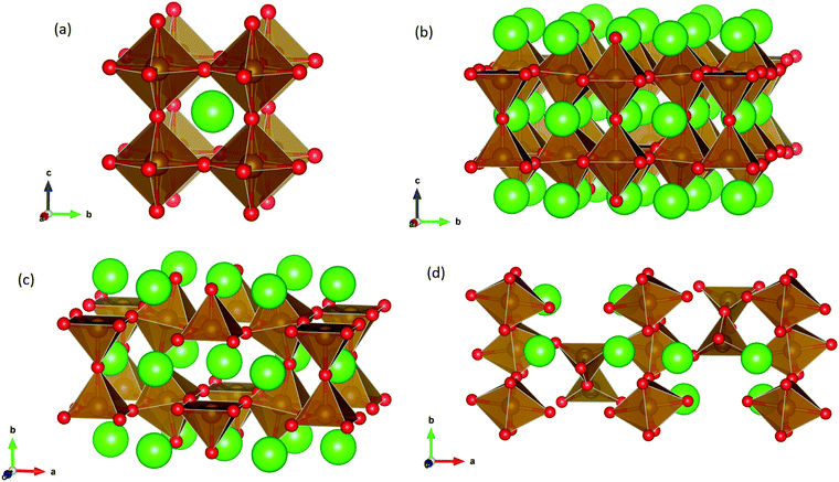
SrFeO3−δ can adopt four different phases at room temperature dependent on the level of oxygen deficiency, with the ideal level being for each δ = 0, 0.125, 0.25 and 0.5 giving iron oxidation states between Fe3+ and Fe4+. These phases are shown in Fig. 3, and their space groups specified in Table 2. In the cubic phase, all iron atoms are octahedral and have a charge of 4+. In the tetragonal and orthorhombic phases, octahedral iron atoms are modelled with a charge of 4+, but the square planar iron atoms are modelled with a charge of 3+. Finally in the brownmillerite phase, all octahedra and tetrahedra were modelled with Fe3+ ions. It is important to acknowledge these as the Buckingham potentials in the model are different for Fe3+ and Fe4+, as displayed in Table 1.The DFT work on SrFeO3−δ![[thin space (1/6-em)]](https://www.rsc.org/images/entities/char_2009.gif) 9 uses electronic relaxation and both pure structures and oxygen vacant structures do not show presence of Fe(3+) ions or O(1−) ions in the structure, so for the purposes of our work, these were not deemed necessary to look into explicitly. However, where necessary, iron charge compensation has been included in defect calculations using charge smearing, rather than a whole charge model. The smearing approach is supported by the DFT conclusion9 that a whole charge model isn’t likely to be accurate.
9 uses electronic relaxation and both pure structures and oxygen vacant structures do not show presence of Fe(3+) ions or O(1−) ions in the structure, so for the purposes of our work, these were not deemed necessary to look into explicitly. However, where necessary, iron charge compensation has been included in defect calculations using charge smearing, rather than a whole charge model. The smearing approach is supported by the DFT conclusion9 that a whole charge model isn’t likely to be accurate.
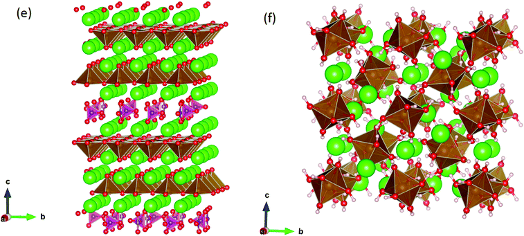
This work studies incorporation of OH− and CO32− in only the cubic and brownmillerite phases due to their relevance to fuel cells, however to ensure transferability in the interatomic potential model, the tetragonal and orthorhombic structures which both contain Fe3+ and Fe4+ ions were optimised using the potentials listed in Table 1 and compared to their experimental structures as well as for the cubic and brownmillerite-type structures, and the Ruddlesden–Popper phase Sr4Fe2O6CO3 and the hydrogarnet Sr3Fe2(OH)12, as shown in Fig. 2. The calculated lattice parameters of all structures shows reasonable agreement with experimental data, as can be seen in Table 2, implying the potential is valid and transferable across all structures and phases, which is not trivial.
3.2 Intrinsic defects
Our results, given in Table 3, show that all possible Frenkel and Schottky defects are unlikely to form spontaneously due to the high formation energies. However, it is important to note that in reality it is well known that oxygen vacancies do form in cubic SrFeO3, with existing literature using DFT methods9 finding the oxygen vacancy formation energy in pure SrFeO3 to be very low, at 0.71 eV. In the work of this paper, the oxygen Frenkel energy is calculated to be 11.1 eV (5.55 eV per defect), which is considerably higher. This is because the real mechanism through which oxygen vacancies form is not of Frenkel-type as shown in Table 3. The real mechanism of oxygen vacancy formation instead involves a neutral  molecule being formed by the reaction:
  and the two remaining electrons reduce surrounding Fe4+.
Table 4 shows that the most likely Frenkel defect is oxygen, with a formation energy of 3.57 eV. This Frenkel involves a vacancy of the oxygen site, corner-sharing between two octahedra. The other intrinsic Frenkel- and Schottky-type defects shown in Table 4 seem unlikely to form spontaneously. These findings are consistent with previous computational classical-potential work31 on SrFeO2.5, which found intrinsic defect energies for the brownmillerite system which are within 1 eV of our findings, despite using different potential parameters.
3.3 Water Incorporation
A series of calculations were performed using the Mott–Littleton method to find the most energetically favourable positions for  and
and  defects.
Water incorporation energies (EH2O) and their energy equations are listed in Table 5. The EPT term describes the proton transfer energy32 of −9.74 eV in the reaction H2O + O2− → 2OH−. There is also a term, EMorse, which accounts for the Morse potential energy released when a water molecule is broken, which is equal to twice the D parameter in the Morse potential between Oh and H.
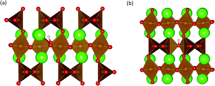
These calculations suggest that mechanisms 1, 2 and 4 are unfavourable, which includes both mechanisms with an  defect as shown in Fig. 3. The most likely mechanism to occur is mechanism 3, with an energy of 1.7 eV, involving a hydroxide ion on an oxygen site
  causing slight octahedral tilting, as shown in Fig. 4. This mechanism however requires a pre-existing oxygen vacancy: hence the oxygen-deficient cubic SrFeO2.7 was also simulated. Experimentally it is well known that pure stoichiometric SrFeO3 is difficult to synthesise due to the natural formation of oxygen vacancies.33 Also, as discussed in Section 3.2.1, results from DFT simulations calculate the oxygen vacancy formation energy to be 0.71 eV. Therefore, it is reasonable to expect that oxygen vacancies will already be present in cubic SrFeO3 and thus the conditions for water incorporation mechanism 3 to occur are likely.
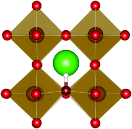 | ||
| Fig. 3 The lowest energy hydroxide ionic defect on an oxygen site in cubic SrFeO3. The hydrogen and hydroxide oxygen are shown by white and dark red spheres respectively. | ||
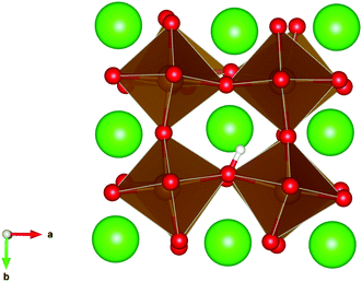 | ||
| Fig. 4 The lowest energy hydroxide ionic defect on an oxygen site in cubic SrFeO2.7, with oxygen vacancies present. | ||
A number of clustering calculations were also performed using the supercell method with a 6 × 6 × 6 cell for two nearby hydroxide molecules on oxygen sites. Results from this suggest that it is slightly more favourable for two  defects to cluster. The most favourable configuration for two hydroxide ions is on two nearest-neighbour oxygen sites where the two hydroxide ions are parallel to one another. The energy of incorporation per water molecule in this case is 1.53 eV, which is 0.17 eV lower than for two infinitely separated hydroxide ions. However, note that this is via mechanism 3 which requires the presence of an oxygen vacancy, thus for clustered hydroxide ions to be on neighbouring sites via water incorporation mechanism 3, two adjacent oxygen vacancies must be present. Clustering calculations for oxygen vacancies suggest that nearby oxygen vacancies repel one another; the difference in energy between two infinitely separated oxygen vacancies and two closest neighbouring ones is 1.32 eV (in favour of being infinitely separated). After considering this, we conclude that despite hydroxide molecules slight preference to cluster, the requirement of closest-neighbour oxygen vacancies makes this unlikely.
The water incorporation mechanisms for the brownmillerite-type system are the same as those enumerated for the cubic system. Water incorporation energies and equations are listed in Table 6.
Similar to the cubic system, a series of calculations were performed using the Mott-Littleton method to find the most favourable positions for  and
and  . These simulations suggest that mechanism 1 is most unlikely, followed by mechanism 2. Mechanism 3 and 4 have energies of under 1 eV and thus would be most likely to occur naturally in SrFeO2.5 exposed to water. Fig. 5 shows the geometry of the most favourable
  and
and  defects respectively. For mechanism 3 which involves
  defects, the structural effect is slight deformation of the regular polyhedral geometry. For mechanism 4 which involves
  defects, the structural impact is more significant as the hydroxide molecule bridges the gap between disconnected tetrahedral chains. This type of defect could have significant implications for oxide ion conductivity and could be a subject of future study.
Both of the more favourable incorporation mechanisms 3 and 4 involve an assumed impurity in the structure: mechanism 3 assumes an oxygen vacancy within the structure before water incorporation and mechanism 4 requires an oxygen interstitial. Given that the oxygen Frenkel energy is 1.8 eV per defect, it seems plausible to expect that the system would already contain a small amount of oxygen vacancies and interstitials. This, coupled with the energy in mechanism 2 of 2.65 eV suggests that water incorporation is viable in brownmillerite-type SrFeO2.5, through mechanisms 2, 3 and 4.
Clustering simulations of brownmillerite-type strontium ferrite yielded similar results as the cubic case. OH− defect pairs on neighbouring oxygen sites in all unique configurations do not differ significantly in energy from OH− defects which are far apart from each other.
3.4 Carbon dioxide incorporation
The reaction which is proposed to take place in carbon dioxide incorporation mechanisms is CO2 + O2− → CO32−,which has an associated energy (analogous to the proton transfer term in the water incorporation mechanisms) of −14.41 eV.13 Possible identified carbon dioxide incorporation mechanisms are shown in Table 7 along with their respective incorporation energies.
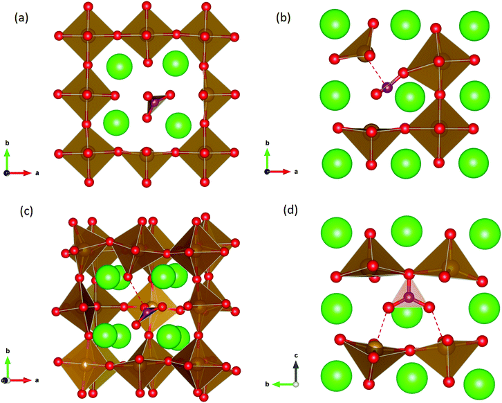
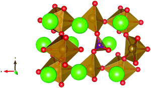
Carbonate incorporation simulations were performed using the super cell method with a 6 × 6 × 6 unit cell size. The mechanisms and corresponding incorporation energies for carbonate in pure cubic SrFeO3 are unfavourable as can be seen from results in Table 7. Our simulations suggest that it is unlikely that any carbonate incorporation mechanisms will occur naturally in cubic strontium ferrite unless it contains iron vacancies and surrounding oxygen vacancies as shown in Table 8. If one assumes existing vacancies however, the carbonate incorporation becomes favourable and the carbonate group is positioned on the iron site and parallel to the plane formed by the oxygen vacancies, as displayed in Fig. 6.
Relative to the cubic system, brownmillerite SrFeO2.5 is less dense, making it intuitively more reasonable to allow a large carbonate anion to be accommodated in the structure, especially considering previous successful oxyanion doping into brownmillerite-type Ba2In2O5.5 It was expected that, similarly to the cubic case, carbonate would exist on the iron site and therefore require iron vacancies and a number of surrounding oxygen vacancies in the pure SrFeO2.5 structure to accommodate it due to the similarity in structure and composition to the cubic system, and the large size of the carbonate anion.
The mechanisms are displayed in Table 9. Supercells consisting of 36 unit cells of brownmillerite SrFeO2.5 have been used. Both carbonate incorporation during and after formation of strontium ferrite show favourable energies.
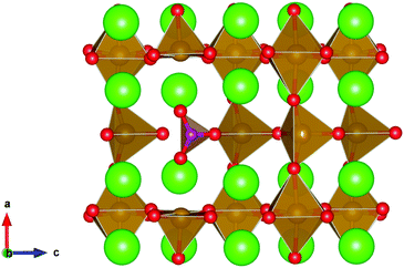
From Table 9 the coordination of the iron site on which the carbonate is placed shows a slight difference. The most favourable is when the carbonate is on the tetrahedral Fe site, which is perhaps not unexpected as this site is most likely to accommodate a trigonal planar carbonate ion, without too much disruption to the structure. The lowest energy arrangements for each are displayed are shown in Fig. 7 and 8.
4 Conclusions
In conclusion, this computational study shows that intrinsic Frenkel or Schottky defects in both pure cubic and brownmillerite-type SrFeO3−δ systems are unlikely to form spontaneously. For pure cubic SrFeO3, water incorporation is likely through defects in the cubic system with oxygen vacancies present and is also plausible in the brownmillerite system via mechanisms including both
  and
and  defects, the latter of which could significantly impact the oxide ion conductivity by increasing disorder.
Calculations in this work also show that carbon dioxide incorporation is unlikely in pure stoichiometric SrFeO3, but if there are iron and oxygen vacancies, carbonate will be accommodated into the cubic structure on the iron site, despite CO32− itself being an anion. Carbonate is known to behave similarly in the related Ruddlesden–Popper phase, Sr3Fe3−x(CO3)xO6O10−4x−y35 and the layered iron oxycarbonate Sr4Fe2O6(CO3).26 Sulphate and borate ions have also recently been doped into SrFeO3−δ.3 The implications for SOFC application are that the structural differences between pure and defective structures will inevitably affect the conductivity and function and should therefore be considered in future studies. In addition, given that there is a growing propensity for utilizing lower temperature (sol–gel) routes to synthesise such fuel cell materials, the results present here imply that the potential incorporation of carbonate and water needs to be considered for these materials.
Conflicts of interest
There are no conflicts to declare.Acknowledgements
The authors would like to thank the EPSRC-funded CDT for Fuel Cells and their Fuels (EP/L015749/1) for funding LJF's studentship. PRS would like to thank the Leverhulme Trust (Exploring carbonate incorporation in “oxide” materials: the hidden dopant in Materials Chemistry (RPG-2017-011)) and the EPSRC for funding the JUICED Hub (Joint University Industry Consortium for Energy (Materials) and Devices Hub EP/R023662/1).References
- N. Mahato, A. Banerjee, A. Gupta, S. Omar and K. Balani, Prog. Mater. Sci., 2015, 72, 141–337 CrossRef CAS.
- A. Jun, J. Kim, J. Shin and G. Kim, ChemElectroChem, 2016, 3, 511–530 CrossRef CAS.
- A. Jarvis and P. R. Slater, Crystals, 2017, 7, 169 CrossRef.
- J. M. Porras-Vazquez, T. Pike, C. A. Hancock, J. F. Marco, F. J. Berry and P. R. Slater, J. Mater. Chem. A, 2013, 1, 11834–11841 RSC.
- J. F. Shin, A. Orera, D. Apperley and P. Slater, J. Mater. Chem., 2011, 21, 874–879 RSC.
- N. Lu, Y. Wang, S. Qiao, H.-B. Li, Q. He, Z. Li, M. Wang, J. Zhang, S. C. Tsang and J. Guo, et al., 2018, arXiv preprint, arXiv:1811.10802.
- P. Gallagher, J. Chem. Phys., 1964, 41, 2429 CrossRef CAS.
- Y. Teraoka, S. Furukawa, H. Zhang and N. Yamazoe, Nippon Kagaku Kaishi, 1988, 1084–1089 CrossRef CAS.
- T. Das, J. D. Nicholas and Y. Qi, J. Mater. Chem. A, 2017, 5, 4493–4506 RSC.
- C. Hancock, J. Porras-Vazquez, P. Keenan and P. Slater, Dalton Trans., 2015, 44, 10559–10569 RSC.
- O. Merkulov, E. Naumovich, M. Patrakeev, A. Markov, E. Shalaeva, V. Kharton, E. Tsipis, J. Waerenborgh, I. Leonidov and V. Kozhevnikov, J. Solid State Electrochem., 2018, 22, 727–737 CrossRef CAS.
- A. J. McSloy, P. F. Kelly, P. R. Slater and P. M. Panchmatia, Phys. Chem. Chem. Phys., 2016, 18, 26284–26290 RSC.
- A. J. McSloy, I. Trussov, A. Jarvis, D. J. Cooke, P. R. Slater and P. M. Panchmatia, J. Phys. Chem. C, 2018, 122, 1061–1069 CrossRef CAS.
- J. D. Gale, J. Chem. Soc., Faraday Trans., 1997, 93, 629–637 RSC.
- J. Gulp and A. Rohl, Mol. Simul., 2003, 29, 291–341 CrossRef.
- K. Momma and F. Izumi, J. Appl. Crystallogr., 2008, 41, 653–658 CrossRef CAS.
- R. A. Buckingham, Proc. R. Soc. London, Ser. A, 1938, 168, 264–283 CAS.
- B. Dick Jr and A. Overhauser, Phys. Rev., 1958, 112, 90 CrossRef.
- G. Lewis and C. Catlow, J. Phys. C: Solid State Phys., 1985, 18, 1149 CrossRef CAS.
- M. Cherry, M. S. Islam and C. Catlow, J. Solid State Chem., 1995, 118, 125–132 CrossRef CAS.
- G. C. Mather, M. S. Islam and F. M. Figueiredo, Adv. Funct. Mater., 2007, 17, 905–912 CrossRef CAS.
- P. M. Morse, Phys. Rev., 1929, 34, 57 CrossRef CAS.
- P. M. Panchmatia, A. Orera, E. Kendrick, J. V. Hanna, M. E. Smith, P. Slater and M. Islam, J. Mater. Chem., 2010, 20, 2766–2772 RSC.
- S. Kerisit and S. C. Parker, J. Am. Chem. Soc., 2004, 126, 10152–10161 CrossRef CAS.
- T. Archer, S. Birse, M. T. Dove, S. Redfern, J. D. Gale and R. Cygan, Phys. Chem. Miner., 2003, 30, 416–424 CrossRef CAS.
- K. Yamaura, Q. Huang, J. Lynn, R. Erwin and R. J. Cava, J. Solid State Chem., 2000, 152, 374–380 CrossRef CAS.
- N. Nevskij, B. Ivanov-Ehmin, N. Nevskaya, G. Z. Kaziev and N. V. Belov, Dokl. Akad. Nauk SSSR, 1982, 264, 857–858 Search PubMed.
- N. Mott and M. Littleton, Trans. Faraday Soc., 1938, 34, 485–499 RSC.
- J. Hodges, S. Short, J. Jorgensen, X. Xiong, B. Dabrowski, S. Mini and C. Kimball, J. Solid State Chem., 2000, 151, 190–209 CrossRef CAS.
- M. Harder and H. Müller-Buschbaum, Z. Anorg. Allg. Chem., 1980, 464, 169–175 CrossRef CAS.
- C. A. Fisher and M. S. Islam, J. Mater. Chem., 2005, 15, 3200–3207 RSC.
- K. Wright, R. Freer and C. Catlow, Phys. Chem. Miner., 1994, 20, 500–503 CAS.
- Y. Takeda, K. Kanno, T. Takada, O. Yamamoto, M. Takano, N. Nakayama and Y. Bando, J. Solid State Chem., 1986, 63, 237–249 CrossRef CAS.
- S. B. Karki, R. K. Hona and F. Ramezanipour, J. Electron. Mater., 2020, 49, 1557–1567 CrossRef CAS.
- Y. Bréard, C. Michel, M. Hervieu and B. Raveau, J. Mater. Chem., 2000, 10, 1043–1045 RSC.
| This journal is © the Owner Societies 2020 |

