 Open Access Article
Creative Commons Attribution 3.0 Unported Licence
In situ X-ray diffraction computed tomography studies examining the thermal and chemical stabilities of working Ba0.5Sr0.5Co0.8Fe0.2O3−δ membranes during oxidative coupling of methane†
Dorota
Matras
 *ab,
Antonis
Vamvakeros
 bcd,
Simon D. M.
Jacques
*c,
Vesna
Middelkoop
 e,
Gavin
Vaughan
 f,
Miren
Agote Aran
 bd,
Robert J.
Cernik
a and
Andrew M.
Beale
 *bcd
*bcd
aSchool of Materials, University of Manchester, Manchester, Lancashire M13 9PL, UK. E-mail: matras.dorota@gmail.com
bResearch Complex at Harwell, Harwell Science and Innovation Campus, Rutherford Appleton Laboratory, Didcot, Oxon OX11 0FA, UK
cFinden Limited, Merchant House, 5 East St Helen Street, Abingdon, OX14 5EG, UK. E-mail: simon@finden.ac.uk
dDepartment of Chemistry, University College London, 20 Gordon Street, London, WC1H 0AJ, UK. E-mail: andrew.beale@ucl.ac.uk
eSustainable Materials Management, Flemish Institute for Technological Research, VITO NV, Boeretang 200, Mol, Belgium
fESRF – The European Synchrotron, Grenoble, 38000, France
First published on 15th June 2020
Abstract
In this study we present the results from two in situ X-ray diffraction computed tomography experiments of catalytic membrane reactors (CMRs) using Ba0.5Sr0.5Co0.8Fe0.2O3−δ (BSCF) hollow fibre membranes and Na–Mn–W/SiO2 catalyst during the oxidative coupling of methane (OCM) reaction. The negative impact of CO2, when added to the inlet gas stream, is seen to be mainly related to the C2+ yield, while no evidence of carbonate phase(s) formation is found during the OCM experiments. The main degradation mechanism of the CMR is suggested to be primarily associated with the solid-state evolution of the BSCF phase rather than the presence of CO2. Specifically, in situ XRD-CT and post-mortem SEM/EDX measurements revealed a collapse of the cubic BSCF phase and subsequent formation of secondary phases, which include needle-like structures and hexagonal Ba6Co4O12 and formation of a BaWO4 layer, the latter being a result of chemical interaction between the membrane and catalyst materials at high temperatures.
1. Introduction
Over the past decades, the potential of membrane reactors towards a cleaner and more sustainable future has become more apparent.1–3 Catalytic membrane reactors (CMRs) are able to simultaneously perform separation and reaction processes offering a unique opportunity to increase the overall system efficiency and decrease the energy consumption in a single unit. More specifically, the application of oxygen permeable membranes with mixed ionic and electronic conductivity (MIEC) properties is an alternative technology for oxygen separation from air.4–6 It offers both reduced costs and high oxygen permeation flux, and more importantly it can be directly integrated with catalytic reactor systems.7–10 The use of perovskite membranes in the oxidative coupling of methane (OCM) process11–15 is believed to provide a more uniform distribution of oxygen along the axial direction when compared to conventional fixed bed reactors. This is expected to directly influence the C2+ yield as the methane can be activated by the surface oxygen ionic species and the contribution of gas phase homogenous combustion reactions can be decreased.16Wang et al.17 studied the OCM reaction using a catalytic membrane reactor with a Ba0.5Sr0.5Co0.8Fe0.2O3−δ tubular membrane and a La–Sr/CaO catalyst packed-bed. Both, the packed-bed catalytic membrane reactor and the catalytic membrane reactor (i.e. membrane only) configurations were tested using similar OCM conditions. Although both configurations showed similar performance for CH4 conversion and C2+ yield, the packed-bed catalytic membrane reactor led to significantly higher C2H4/C2H6 ratio (12.5 as opposed to 1 for the catalytic membrane reactor). Czuprat et al.18 investigated the Na–Mn–W/SiO2 catalyst packed inside the hollow fibre BaCoxFeyZrzO3−δ (x + y + z = 1) membrane. A C2+ yield of 17% and C2H4/C2H6 ratio of 4 was obtained for a CH4 conversion of 35% (using a pure stream of air on the core/feed side). In the study of Bhatia et al.19 three configurations were investigated for the OCM reaction: packed-bed reactor, packed-bed catalytic membrane reactor and catalytic membrane reactor with coated Na–Mn–W/SiO2 catalyst. The latter configuration was found to perform the best among the three configurations, with a C2+ yield of 35% and C2H4/C2H6 ratio of 1.4. The changes in the catalytic membrane material were analysed postreaction with XRD and SEM analysis; catalyst components were found to migrate towards the reaction surface, whereas cation species from the membrane migrated towards the oxygen-enriched surface.
In this work we investigate a Ba0.5Sr0.5Co0.8Fe0.2O3−δ (BSCF) hollow fibre membrane during the oxidative coupling of methane; this perovskite is known to have excellent oxygen permeability7,20–22 at operating temperatures required for this reaction (∼2 S mL min−1 cm−2![[thin space (1/6-em)]](https://www.rsc.org/images/entities/char_2009.gif) 23). However, there are still several challenges related to the long-term phase stability and chemical poisoning of this material that prevent its application under real industrial conditions. More precisely, at intermediate temperatures (i.e. below 850 °C) the cubic BSCF phase has been observed to decompose to secondary Ba and Co hexagonal phases with a simultaneous decrease in oxygen permeation.24–29 The reason behind the instability of the cubic phase has been attributed to a change in the oxidation state of Co upon exposure to air below 850 °C. According to the Goldschmidt tolerance factor,30 the cubic structure is not able to accommodate Co with higher oxidation states31 and thus the more stable hexagonal phase is expected to form. The formation of the secondary hexagonal phase was identified to take place at the grain boundaries from the feed side (air exposed side), but over a long duration experiment (i.e. 1000 s of hours of operation) this phase can also be identified in the grains.32–34 The high internal stress resulting from this phenomenon was suggested to be responsible for the formation of cracks in the membrane reactor.35
23). However, there are still several challenges related to the long-term phase stability and chemical poisoning of this material that prevent its application under real industrial conditions. More precisely, at intermediate temperatures (i.e. below 850 °C) the cubic BSCF phase has been observed to decompose to secondary Ba and Co hexagonal phases with a simultaneous decrease in oxygen permeation.24–29 The reason behind the instability of the cubic phase has been attributed to a change in the oxidation state of Co upon exposure to air below 850 °C. According to the Goldschmidt tolerance factor,30 the cubic structure is not able to accommodate Co with higher oxidation states31 and thus the more stable hexagonal phase is expected to form. The formation of the secondary hexagonal phase was identified to take place at the grain boundaries from the feed side (air exposed side), but over a long duration experiment (i.e. 1000 s of hours of operation) this phase can also be identified in the grains.32–34 The high internal stress resulting from this phenomenon was suggested to be responsible for the formation of cracks in the membrane reactor.35
The second major challenge is related to the interaction of the BSCF material with CO2. In many studies, the formation of BaCO3 (or BaxSr1−xCO3) has been reported to have a detrimental effect on the oxygen permeation.36,37 A thin layer of this carbonate phase forming at the surface of the membrane is considered to act as a barrier for the oxygen ion transport. In a study by Engels et al.,38 15% of CO2 in the permeated side gradually decreased the initial oxygen permeation flux by 80% after 200 min of operation. Although the effect of CO2 was found to be reversible, as the initial oxygen permeation flux could be restored when changing the composition of the sweep side to pure He, minor structural changes in the membrane were induced during this process; these may be considered important for the long term stability of BSCF membranes. Finally, as recently reported by Vamvakeros et al.,39,40 Ba-containing membranes may also be susceptible to chemical poisoning by WO42− species. During the OCM reaction, a thin layer of BaWO4 was found to form at the interface between a Na–Mn–W/SiO2 catalyst and a hollow fibre BaCoxFeyZrzO3−δ (BCFZ) membrane. Although there was no direct change in the reactor performance, the loss of catalyst components coupled with the formation of the stable BaWO4 layer was proposed to have a significant impact on the long-term performance of this integrated reactor system.
The aim of this work was to assess the aforementioned issues and their implication on the performance of working catalytic membrane reactors for the oxidative coupling of methane reaction. We employed the X-ray diffraction computed tomography (XRD-CT) technique41,42 to investigate the evolution of the solid-state chemistry in the BSCF membrane in two experiments. The first experiment involved exposing the BSCF membrane to 20% CO2/CH4 gas stream (permeate side) for 11 h. In the second experiment, the Na–Mn–W/SiO2 catalyst was placed inside the BSCF membrane and the packed-bed catalytic membrane reactor was tested for the OCM reaction with different concentrations of CO2 in the CH4 stream (permeate side). The solid-state changes observed from the XRD-CT data are discussed and compared with laboratory mass spectrometry and post-reaction SEM/EDX measurements.
2. Materials and methods
2.1. Preparation of hollow fibre BSCF membrane
The BSCF perovskite hollow membranes were supplied by the Flemish Institute for Technological Research (VITO), prepared from the BSCF mixed ionic–electronic conducting perovskite powder obtained from CerPoTech (Norway). Membranes were prepared using the spinning and phase inversion technique previously reported in the work of Di Felice et al.23 The dimensions of the BSCF membranes used for both experiments were: 3.6–3.7 mm outside diameter and 2.8–2.9 mm inside diameter.2.2. In situ XRD-CT measurements at ID15A, ESRF
XRD-CT measurements were performed at ID15A beamline at the ESRF43 using a monochromatic beam of 95 keV with a size of 40 μm × 90 μm (H × V). For both experiments BSCF membranes were placed inside a quartz reactor (6 mm outside diameter and 4 mm inside diameter). A schematic representation of the experimental setup can be found in Fig. S1 (ESI†). Two different experiments were performed: (1) with catalytic membrane reactor and (2) with packed-bed catalytic membrane rector using 60 mg of Na–Mn–W/SiO2 catalyst placed inside the BSCF membrane and supported between glass wool. During the first experiment (with pure membrane reactor) the sample was scanned using 150 translation steps (with 40 μm step) and 100 angular steps (with 1.8° step), whereas during the experiment with packed-bed catalytic membrane reactor sample was scanned using 140 translation steps (with 40 μm step) and 120 angular steps (1.5° step). Diffraction patterns were collected using a PILATUS3 X CdTe (Dectris) area detector. The calibration of the detector was performed using a CeO2 NIST standard. Every collected 2D diffraction image was converted to 1D powder diffraction patterns using PyFAI software44 using the nDTomo software45 with implemented trimmed mean filter (20%) to remove the artefacts due to hot spots of (single) crystalline materials.46 The reconstructed images were obtained using the filtered back projection algorithm. For both experiments the XRD-CT data were corrected for the self-absorption using a zero-order approximation. The detailed description of the self-absorption correction strategy can be found elsewhere.472.3. In situ OCM experiments at ID15A, ESRF
Fig. S2 (ESI†) shows the photograph of the experimental setup used during the in situ measurements. In both experiments two separate gas streams were delivered to the reactor cell. During the temperature ramp up to 820 °C, the sample was heated under atmosphere of 50 sccm Ar (inner side gas stream) and 50 sccm air (outer side gas stream) with a temperature ramp of 20 °C min−1. Pure gases of air, CH4, CO2 and Ar were delivered to the reactor by mass flow controllers (Brooks). The OCM reaction was performed at atmospheric pressure and the outlet gases were analysed by mass spectrometry using an Ecosys portable mass spectrometer. The sample was heated using an in-house developed box furnace. In the case of the first experiment, we investigated the long-term stability (11 h) of the BSCF membrane during the OCM reaction, using a CH4 stream co-fed with 20% of CO2. The outer side gas stream delivered 50 sccm of air and the inner side gas stream delivered 80 sccm of CH4 and 20 sccm of CO2. In the case of the second experiment, the solid-state interaction between the membrane and catalyst materials was investigated, testing different compositions of OCM reaction mixtures (CH4 stream also co-fed with CO2). The outer side gas stream delivered 50 sccm of air and the inner side gas stream delivered OCM mixture co-feed with 0, 10, 20, 50 and 100% of CO2 in CH4/CO2 mixture, keeping the 100 sccm as total flow of inner side gas stream. The experimental protocol details for both experiments can be found in the ESI† (Fig. S3 and S4).2.4. Analysis of reconstructed diffraction patterns
The summed diffraction patterns from each XRD-CT dataset were analysed with the X’Pert HighScore Plus software to identify which phases were present and create the model necessary for the Rietveld refinement. The identified phases together with crystallographic information are presented in Table S1 (ESI†). The analysed diffraction patterns were extracted only from pixels where the membrane or catalyst particles were present (the regions of air, reactor and voids between particles were masked). The batch refinement analysis using the reconstructed diffraction patterns was performed using the software Topas v5.48 For both measurements, individual reflections of the cubic perovskite (space group Pm![[3 with combining macron]](https://www.rsc.org/images/entities/char_0033_0304.gif) m) were fitted, in order to follow the relative changes in peak intensities (referred as hkl_phase in Topas). In addition, the application of a 20% trimmed mean filter for data correction,46 especially in the case of second experiment, affected the relative intensity of each peak (i.e. spotty data). Therefore, Pawley instead of Rietveld refinement analysis was used as a means to overcome the intensity mismatch problem. In addition, due to the significant thermal expansion of the ceramic material during the temperature ramp, the relative changes in peak intensities were compared only using the measurements performed at high temperatures. The scattering signal originating from catalyst particles (low absorbing and weakly scattering material) was highly altered by the membrane signal (highly absorbing and strongly scattering material) and therefore it was not possible to perform refinement analysis using these diffraction patterns. The distribution of each component is based on the summed intensity of a corresponding diffraction peak in the XRD-CT data.
m) were fitted, in order to follow the relative changes in peak intensities (referred as hkl_phase in Topas). In addition, the application of a 20% trimmed mean filter for data correction,46 especially in the case of second experiment, affected the relative intensity of each peak (i.e. spotty data). Therefore, Pawley instead of Rietveld refinement analysis was used as a means to overcome the intensity mismatch problem. In addition, due to the significant thermal expansion of the ceramic material during the temperature ramp, the relative changes in peak intensities were compared only using the measurements performed at high temperatures. The scattering signal originating from catalyst particles (low absorbing and weakly scattering material) was highly altered by the membrane signal (highly absorbing and strongly scattering material) and therefore it was not possible to perform refinement analysis using these diffraction patterns. The distribution of each component is based on the summed intensity of a corresponding diffraction peak in the XRD-CT data.
2.5. Laboratory mass spectrometry and gas chromatograpgy measurements
Complementary OCM experiments to the in situ experiments performed at the ID15A beamline were also performed in the laboratory. In contrast to the in situ measurements, the reactor used in the laboratory measurements was closed from both ends; two inlets streams and two outlets streams were connected to the reactor using nonporous alumina rods. The sample was placed inside a quartz reactor, itself placed inside a horizontal tubular furnace (Carbolite). In the case of the packed-bed catalytic membrane reactor, 68 mg of Na–Mn–W/SiO2 catalyst was placed inside the BSCF membrane supported by quartz wool.A schematic representation of the experimental setup used in the laboratory measurements is presented in Fig. S5 (ESI†). Gases: 20% of O2/He, 50% of CH4/Ar, CO2 and N2 were delivered to the reactor by mass flow controllers (Brooks). The OCM reaction was performed at atmospheric pressure and the outflow gases were analysed by mass spectrometry, using an Ecosys portable mass spectrometer, and by gas chromatography, using the SRI 8610C Gas Chromatograph (Molecular Sieve 13X and Haysep 6D columns) equipped with FID and TCD detectors. The inner side gas stream was cooled with an ice bath to collect the produced water (in the case of the experiment with packed-bed catalytic membrane reactor). The experimental setup allowed, by adjusting accordingly the valves, switching between the two streams and choosing which one was probed by mass spectrometry. Prior to the experiments, the membrane sealing was tested by measuring the gas flow from the sweep outlet 2 (outer side gas stream) while using only an inert gas to the reactor through inlet 1 (inner side gas stream). This way the sealing of both membrane sections was tested. During the temperature ramp, only the gas stream flow outlet 2 was probed in order to ensure the sealing did not fail during the high temperature treatment. Before introducing the OCM reaction mixture the valves were adjusted to probe the outlet 1 (inner side gas stream). The experimental protocol for both experiments can be found in Tables S2 and S3 (ESI†).
3. Results
3.1. Catalytic membrane reactor
The initial distribution of the membrane components is presented in Fig. 1. The membrane composition was found to be non-uniform, as two distinct regions can be observed in the acquired cross section. On the left side, the majority of the material consisted of cubic BSCF perovskite, whereas the right side contained Co3O4, BaCO3 and an additional phase (Fig. S6 and S7, ESI†). This unusual distribution of membrane materials was not a measurement artefact and it was most likely formed during the membrane preparation. However, it is important to note that the membrane primarily consists of the BSCF phase while the other phases are present in minor quantities (Fig. S7, ESI†).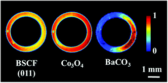 | ||
| Fig. 1 Distribution of the BSCF, Co3O4 and BaCO3 phases in the asprepared membrane at room temperature. | ||
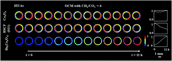
Fig. 2 shows the distribution of the membrane components (Co3O4 and Ba6Co4O12) as well as the distribution of the cubic perovskite (the main (011) reflection) during the high temperature scans under Ar and under OCM reaction conditions. It is important to note that the initially present BaCO3 decomposed during the temperature ramp and no other carbonate phase formed during the experiment. The results from the refinement analysis showed that the BSCF phase was not stable under OCM operating conditions (Fig. S7, ESI†). More precisely, after around 3 h of operation, a secondary hexagonal phase, identified as Ba6Co4O12, started to form at the region where the cubic perovskite was initially present in the fresh material. As mentioned previously, the instability of the cubic perovskite is expected to occur during operation of the membrane at intermediate temperatures. Different compositions and morphologies of this secondary phase have been previously reported24,33,35 however the hexagonal phase is expected to contain mainly Ba and Co. During the OCM reaction the intensities of all BSCF reflections were seen to gradually decrease, whereas the Co3O4 remained stable for the duration of the experiment.
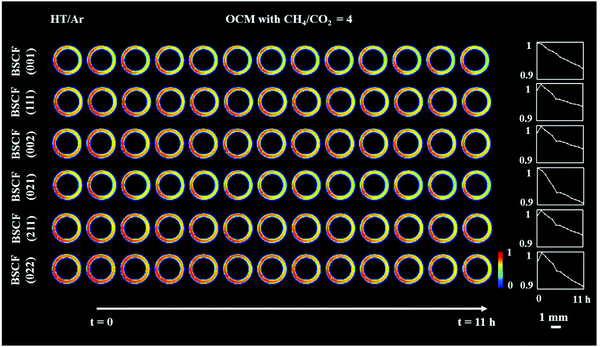
Although all BSCF reflections are seen to gradually decrease with time (Fig. 3), an unusual behaviour can be observed between the 1st and 2nd XRD-CT scan; the intensity of the (011), (111), (002), (211) and (022) reflections increased whereas the intensity of the (001) and (021) reflections decreased. In addition, after the introduction of the OCM reaction mixture, the lattice parameter of the cubic perovskite decreased from 4.015 to 4.013 Å (Fig. S8, ESI†). This observation can be explained by the contraction of the lattice parameter, through the oxidation of the transition metals occupying the perovskite B site. This would also suggest a decrease in oxygen vacancies in order to maintain the charge neutrality of the structure.49 The gradual decrease in lattice parameter during the OCM reaction, from 4.013 to 4.011 Å is most likely caused by the change in the structure of the cubic perovskite; the formation of hexagonal Ba6Co4O12 phase resulted in the decrease of Ba and Co in the resulting cubic perovskite, which is in agreement with previously reported studies.34,50
In order to rationalise the subtle changes in the peak intensities, further analysis was performed focusing on how the structural changes in the cubic BSCF (i.e. occupancy of each element at A and B sites, oxygen occupancy) affect the intensity of certain reflections. The simulation of BSCF diffraction patterns with different chemical composition can be found in the ESI† (Section S3, Simulation of BSCF structure). Considering the relative changes in the simulated data, we conclude that the changes in the BSCF structure between HT/Ar and OCM XRD-CT scan were due to the increase in oxygen occupancy, which corresponds to a decrease in oxygen vacancies (Table S4, ESI†). Although the changes in the intensity of the (011) and (211) reflections are contradictory to the results of the simulated data, the relative changes in the simulated data are minor and therefore it is not possible to rule out that the changes in intensity may also be due to changes in the amounts of Co and Ba. The decrease in oxygen permeability is expected to occur during the introduction of the OCM reaction mixture (changing gas environment from He to CH4), as the CO2 (produced from combustion) reacts with the membrane forming a layer of BaCO3. However, the XRD-CT measurements (X-ray beam size of 40 μm × 90 μm) did not detect the presence of any carbonate phases. The relative changes in the BSCF structure though is a clear indication of the oxygen permeation changing as a function of the imposed operating conditions. As the perovskite was found to be unstable during the OCM reaction conditions, the decrease in intensity of all BSCF reflections during the experiment is attributed to the ongoing decomposition of this phase. The decomposition of BSCF during operation as well as the formation of Co3O4, BaCO3 and the unidentified phase(s) during the preparation indicate inherent problems associated with the chemical stability of the perovskite phase.
3.2. Catalytic membrane reactor with Na–Mn–W/SiO2 packed-bed
The distribution of the fresh membrane components at ambient conditions is presented in Fig. 4. Initially, the membrane consisted primarily of the BSCF perovskite while minor quantities of CoO and Co3O4 were also present. It is important to note that the BaCO3 phase seen in the first experiment was not observed here (Fig. S14, ESI†). During the temperature ramp performed under air/Ar, the quantity of CoO significantly decreased which could be explained by the oxidation of Co2+ to Co3+ in the presence of air at high temperatures. The disappearance of CoO and simultaneous increase in Co3O4 is clearly visible by the relative changes in the diffraction patterns collected at room temperature and operating temperature (Fig. S14, ESI†).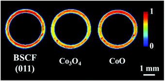 | ||
| Fig. 4 Distribution of the BSCF, Co3O4 and CoO phases in the as-prepared membrane at ambient conditions. | ||
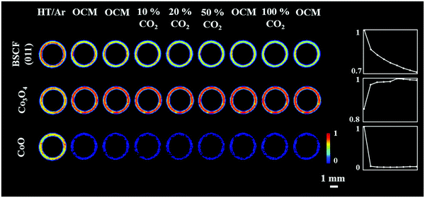
The distribution of the membrane components as well as the relative changes during the OCM reaction are shown in Fig. 5. After the introduction of the OCM reaction mixture, the CoO was found to completely disappear from the membrane material, whereas the distribution and quantity of Co3O4, after the initial formation/growth from the CoO, was found to remain stable until the end of the experiment. Regarding the BSCF phase, the relative changes in its primary reflection ((011) at 2Th = 2.6° in Fig. S15, ESI†) showed that the quantity of the perovskite gradually decreased with the greatest reduction observed after the introduction of the OCM reaction mixture. A similar trend was observed for the other cubic BSCF reflections (Fig. S15, ESI†). However, in contrast to the previous experiment, no changes in the lattice parameter of the cubic structure occurred with time; its value remained constant and was determined to be 4.045 Å (Fig. S16, ESI†).
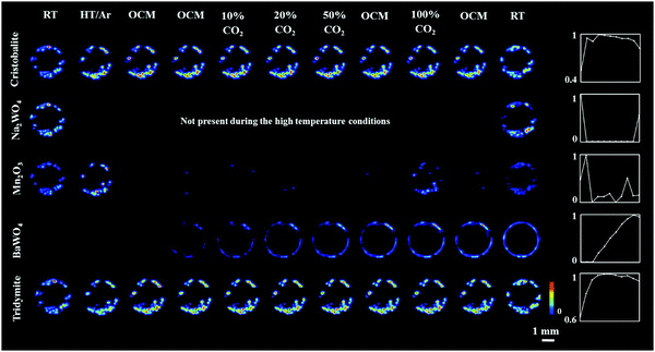
The results of the refinements clearly show that the BSCF material was not stable during the OCM experiment. More importantly, a new phase, identified as BaWO4 was seen to form at the interface between membrane and catalyst material at the beginning of the second XRD-CT scan under OCM conditions with pure CH4. The distribution of all catalyst components and the BaWO4 is presented in Fig. 6.
The BaWO4 was formed as a result of an interaction between the catalyst and membrane material. As observed previously,39 the Na+ and WO42− species are volatile and they can interact with the reactor vessel at high temperatures (i.e. above 780 °C).51 In this experiment the WO42− species were found to migrate towards the membrane material where they interacted with Ba2+ present in the cubic perovskite, forming a continuous layer of BaWO4 at the membrane-catalyst interface. A similar observation was made in the case of operando studies with a BaCo0.4Fe0.4Zr0.2O3−δ perovskite membrane and a Na–Mn–W/SiO2 catalyst.39,40 It is possible that this phenomenon can have a detrimental effect on the overall long-term performance of the CMR reactor as the newly formed layer is expected to have a negative impact on the oxygen permeability while the loss of catalyst active species is also bound to affect its performance. Similarly to the first experiment, no significant changes in the membrane were detected when CO2 was co-fed with CH4; there was no evidence for carbonate phases formation in this experiment.
Regarding the solid-state chemistry of the other catalyst components, the temperature induced a gradual transition between cristobalite and tridymite during the OCM reaction.51,52 In addition, the Mn2O3 phase was seen to disappear after the introduction of the OCM reaction mixture. However, it temporarily reappeared after the introduction of the reaction mixture containing pure CO2 (possibly due to the CO2 reduction by Mn2+/Mn3+). This observation is in good agreement with previous work on a Na–Mn–W/SiO2 catalyst-membrane system;51,53 the active catalyst does not need to contain the crystalline Mn2O3 phase. It is also clear that in the presence of CH4, the crystalline Mn2O3 loses its long-range order, most likely due to bulk reduction to Mn2+. However, no crystalline phase containing Mn2+ (i.e. MnWO4) was seen to form during the OCM reaction. It should finally be noted that minor changes in the distribution of catalyst components between room temperature and high temperature XRD-CT scans were attributed to minor movement of catalyst particles during the introduction of gas to the reactor (i.e. loose packing).
3.3. Laboratory peformance testing and ex situ SEM/EDX characterisation
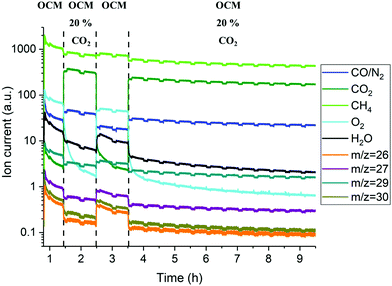
Complementary laboratory catalytic performance experiments were designed and performed in order to further support and rationalise the solid-state chemistry observations from the in situ XRD-CT measurements. However, small changes to the experimental protocol had to be made in order to advance our understanding of the working system (i.e. duration of experiment, additional steps related to co-feeding CH4/CO2). The reactor outlet gases were analysed with mass spectrometry (MS) and gas chromatography (GC); however, the analysis is only qualitative due to the dead volume of the experimental setup introduced by the large condenser/catch pot after the reactor and before the analytical instruments which led to diluted streams and a corresponding delay in observing the changes in gas phase composition. The recovered samples after the laboratory experiments were analysed with scanning electron microscopy (SEM) coupled with energy dispersive X-ray analysis (EDX).The results of the MS data collected during the OCM reaction with the catalytic membrane reactor are presented in the Fig. 7. With the addition of CO2 in the reactor inlet stream (inner side stream) the most apparent changes are related to the O2 signal, as it was found to gradually decrease after the introduction of 20% CO2 in the CH4 stream. Changing the gas composition to CH4 (50% of CH4 in Ar) resulted in the recovery of the oxygen permeability which was found to decrease again in the second cycle with 20% of CO2. However, during this second cycle, the oxygen MS signal was seen to decrease faster than during the first cycle. The O2 signal continued to gradually decrease until the end of experiment. The GC measurements showed that the BSCF membrane exhibits poor activity for the OCM reaction and the additional CO2 in the reactor inlet stream further decreases it (Fig. S19, ESI†).
The elemental distribution of the membrane components at the inner side of the membrane is presented in Fig. 8. The results from the EDX mapping measurements showed that there is a segregation of CoOx species in the membrane material (Fig. 9). At the same time, the SEM images revealed the presence of a thin layer of ∼5 μm on the membrane surface which possesses a different structure (needle-like) when compared to membrane bulk (dense structure). The formation of the needle-like structure in the BSCF membrane has been previously reported in the work of Engels et al.38 however no exact information regarding its composition and structure was presented. The EDX mapping measurements showed that there was no significant difference in the elemental composition between the surface layer and the dense bulk of the membrane. The morphology of this new structure resembles the morphology of the secondary phases formed in the BSCF during operation under temperatures below 900 °C.34,54,55
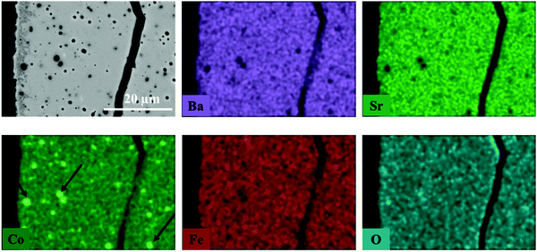 | ||
| Fig. 8 Elemental distribution of membrane components at the inner side of membrane obtained by EDX mapping. This fragment of membrane cross section was obtained from the reactor inlet. | ||
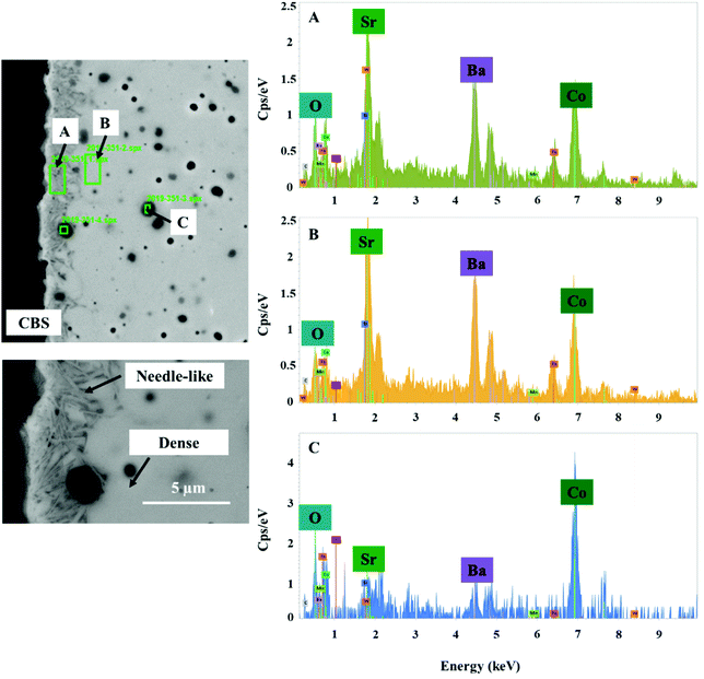 | ||
| Fig. 9 SEM image of the inner side of the membrane and the corresponding energy spectrum from chosen regions. This fragment of the membrane cross section was obtained from the reactor inlet. | ||
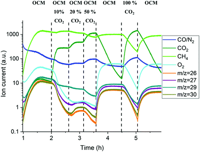
The mass spectrometry results collected with the packed-bed catalytic membrane reactor are shown in Fig. 10. As mentioned previously, the changes in the MS signal were slower due to the large dead volume after the reactor, however it is still possible to observe the general trend in the gas phase composition. The gradual introduction of CO2 into the OCM reaction mixture (from 10 to 50%) resulted in a decrease of oxygen permeation as well as lower production of C2+ molecules (Fig. S20, ESI†). It is important to note that the difference in the C2+ production between the 1st and 2nd stage of the OCM reaction (1–2 h and 3.5–4.5 h respectively) was mainly caused by the introduction of another CH4![[thin space (1/6-em)]](https://www.rsc.org/images/entities/char_2009.gif) :
:![[thin space (1/6-em)]](https://www.rsc.org/images/entities/char_2009.gif) O2 ratio (3.5 vs. 2.5). As reported previously,56,57 at higher CH4
O2 ratio (3.5 vs. 2.5). As reported previously,56,57 at higher CH4![[thin space (1/6-em)]](https://www.rsc.org/images/entities/char_2009.gif) :
:![[thin space (1/6-em)]](https://www.rsc.org/images/entities/char_2009.gif) O2 ratios the production of C2+ is seen to increase. However, a lower production of C2+ molecules, when compared to the 2nd and 3rd OCM measurement performed at the same CH4
O2 ratios the production of C2+ is seen to increase. However, a lower production of C2+ molecules, when compared to the 2nd and 3rd OCM measurement performed at the same CH4![[thin space (1/6-em)]](https://www.rsc.org/images/entities/char_2009.gif) :
:![[thin space (1/6-em)]](https://www.rsc.org/images/entities/char_2009.gif) O2 ratio, can be explained by the solid-state changes in the membrane primarily associated with the formation of the BaWO4 layer.
O2 ratio, can be explained by the solid-state changes in the membrane primarily associated with the formation of the BaWO4 layer.
The elemental distribution of the catalyst and membrane components at the inner side of the membrane near the reactor inlet is presented in Fig. 11. The results from the EDX mapping revealed that during the OCM reaction there was an interaction between volatile W-containing species and the BSCF membrane which led to the formation of thin deposits on the membrane surface, at the interface between membrane and catalyst particles. This observation further supports the results obtained from the in situ XRD-CT data where it was shown that a BaWO4 formed during the OCM experiment. In addition, these deposits were seen to contain Na and Mn species. Similarly to the previous experiment with the BSCF membrane, Co species were present in the form of large agglomerates containing CoOx species but in addition they were also seen to agglomerate at the membrane surface, forming a uniform layer.
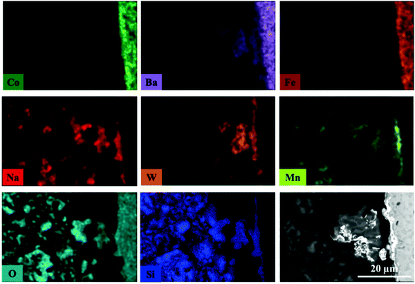 | ||
| Fig. 11 Elemental distribution at the inner side of membrane obtained by EDX mapping. This fragment of the membrane cross section was obtained from the reactor inlet. | ||
The EDX mapping measurements were also performed for inter and intra particle investigation of the distribution of the catalyst active components (Fig. S22, ESI†). The Na and Mn containing species are seen to be present in the catalyst particles as well as in the deposits on the membrane surface, whereas the W-containing species are seen to be present in the deposits and in the particles interacting with the membrane. These observations suggest that all active catalyst components are seen to migrate towards the membrane surface during the OCM reaction, with the W-containing species being the most prone to migration/volatilisation. In addition, the remaining Na and Mn containing species in catalyst particles are seen to have similar and rather uniform distribution; no formation of agglomerates with high concentration of material.
4. Summary and conclusions
In this work, we presented in situ XRD-CT studies of two catalytic membrane reactors consisting of BSCF hollow fibre membranes and a Na–Mn–W/SiO2 catalyst. The spatially-resolved diffraction patterns obtained under operating conditions coupled with laboratory MS measurements and SEM/EDX post-reaction measurements revealed that there are several challenges that need to be addressed before the BSCF membrane can be used for the industrial application of the OCM process.More specifically, the long-term operation of the BSCF membrane at intermediate temperatures (i.e. 825 °C) resulted in the gradual decomposition of the BSCF to secondary phases; the XRD-CT measurements identified the formation of a hexagonal phase containing in majority Ba and Co species (Ba6Co4O12) while the SEM measurements indicated the formation of a new structure (needle-like) around the edge of membrane. However, the EDX mapping measurements did not reveal any chemical difference between the needle-like structure and the membrane dense structure. In addition, the formation of the secondary phases during operation of the BSCF membrane was shown to cause a gradual decrease in oxygen permeation.
In the case of the packed-bed catalytic membrane reactor, a chemical interaction between the membrane and catalyst was observed; at high temperature the W species were seen to migrate towards the membrane surface forming a layer of BaWO4. The additional SEM/EDX measurements on the recovered samples revealed that also Na and Mn species migrated towards the membrane but to a lesser extent. With the MS measurements, the formation of the BaWO4 layer was directly seen to have a detrimental effect on the membrane performance, as the production of C2+ molecules was seen to decrease during the OCM measurements performed in between the CO2 cycling. The BaWO4 formed at the interface between the catalyst particles and membrane is believed to suppress the oxygen permeation and may have indirectly led to a reactor type change, specifically to fixed-bed type with co-fed CH4 and O2. The behavior of the W species results from the intrinsic instability of Na–Mn–W/SiO2 catalyst at high temperatures and under operating conditions; this problem could potentially be solved through the chemical promotion and/or thermal treatment.51,52
Regarding the poisoning effect of CO2, the laboratory measurements showed that the addition of CO2 (from 10% to 100%) to the reaction mixture significantly affected the oxygen permeation and thus the production of C2+ molecules. In all measurements, the CO2 effect was reversible and the initial performance could be recovered when removing the CO2 from the reaction mixture. It should be noted thought that both in situ XRD-CT and ex situ SEM/EDX mapping of the recovered membrane samples did not provide any evidence for carbonate species formation or elemental segregation. This implies that if any carbonate species formed at the membrane surface, these are in not in large quantities and indeed below the detection limit of the techniques applied in this work (i.e. instruments and experimental conditions). The structural changes and formation of BaWO4 were seen to be the main mechanisms behind the long-term degradation of the investigated CMRs. It is concluded that the CO2 produced from CH4 combustion/oxidation processes during the OCM reaction does not significantly affect the oxygen permeation. However, as shown in this work, using the CO2 as the reactor diluent has a negative effect on the membrane reactor performance and should be avoided.
Author contributions
Experimental plan, D. M., A. V., S. D. M. J. and A. M. B.; Material preparation, V. M. Synchrotron measurements, D. M., A. V., M. A. A. and A. M. B., Beamline support, G. V.; Data analysis, D. M. and A. V.; SEM/EDX measurements, V. M.; Original draft preparation, D. M. and A. V.; Writing—review and editing, all authors.; supervision, S. D. M. J., R. J. C. and A. M. B.; funding acquisition, S. D. M. J. and A. M. B.Data availability
Copies of raw radially integrated XRD-CT data can be found at https://rcahdrive.rc-harwell.ac.uk/index.php/s/75ZywcMDqmzi6Hn. All data are available from the corresponding authors on reasonable request.Funding
This project has received funding from the European Union's Horizon 2020 research and innovation programme under Grant Agreement No. 679933 (MEMERE project). A. M. B. acknowledges EPSRC (award EP/K007467/1) for funding.Conflicts of interest
The authors declare no conflict of interest.Acknowledgements
The authors would like to acknowledge Nicolas Grosjean, Stephen Poulston and Benjamin Rollins (Johnson Matthey Technology Centre, Sonning Common) for providing the catalyst material used in this study. The authors would like to thank Marco di Michiel, Thomas Buslaps and Denis Duran for their help during the beamtime experiments at beamline ID15A of the ESRF.References
- G. Zhang, W. Jin and N. Xu, Design and Fabrication of Ceramic Catalytic Membrane Reactors for Green Chemical Engineering Applications, Engineering, 2018, 4, 848–860 CrossRef CAS.
- S. Smart, S. Liu, J. M. Serra, A. Basile and J. C. Diniz da Costa, Perovskite membrane reactors: Fundamentals and applications for oxygen production, syngas production and hydrogen processing, Woodhead Publishing Limited, 2013 Search PubMed.
- A. Julbe, D. Farrusseng and C. Guizard, Porous ceramic membranes for catalytic reactors—overview and new ideas, J. Membr. Sci., 2001, 181, 3–20 CrossRef CAS.
- Y. Wei, W. Yang, J. Caro and H. Wang, Dense ceramic oxygen permeable membranes and catalytic membrane reactors, Chem. Eng. J., 2013, 220, 185–203 CrossRef CAS.
- C. Zhang, J. Sunarso and S. Liu, Designing CO2-resistant oxygen-selective mixed ionic-electronic conducting membranes: Guidelines, recent advances, and forward directions, Chem. Soc. Rev., 2017, 46, 2941–3005 RSC.
- V. Kharton, A. Yaremchenko, A. Kovalevsky, A. Viskup, E. Naumovich and P. Kerko, Perovskite-type oxides for high-temperature oxygen separation membranes, J. Membr. Sci., 1999, 163, 307–317 CrossRef CAS.
- J. Sunarso, S. S. Hashim, N. Zhu and W. Zhou, Perovskite oxides applications in high temperature oxygen separation, solid oxide fuel cell and membrane reactor: A review, Prog. Energy Combust. Sci., 2017, 61, 57–77 CrossRef.
- H. Wang, C. Tablet, A. Feldhoff and J. Caro, A Cobalt-Free Oxygen-Permeable Membrane Based on the Perovskite-Type Oxide Ba0.5Sr0.5Zn0.2Fe0.8O3-δ, Adv. Mater., 2005, 17, 1785–1788 CrossRef CAS.
- Z. Shao, H. Dong, G. Xiong, Y. Cong and W. Yang, Performance of a mixed-conducting ceramic membrane reactor with high oxygen permeability for methane conversion, J. Membr. Sci., 2001, 183, 181–192 CrossRef CAS.
- U. Balachandran, J. T. Dusek, P. S. Maiya, B. Ma, R. L. Mieville, M. S. Kleefisch and C. A. Udovich, Ceramic membrane reactor for converting methane to syngas, Catal. Today, 1997, 36, 265–272 CrossRef CAS.
- J. E. ten Elshof, H. J. M. Bouwmeester and H. Verweij, Oxidative coupling of methane in a mixed-conducting perovskite membrane reactor, Appl. Catal., A, 1995, 130, 195–212 CrossRef CAS.
- Y. Zeng, Y. S. Lin and S. L. Swartz, Perovskite-type ceramic membrane: synthesis, oxygen permeation and membrane reactor performance for oxidative coupling of methane, J. Membr. Sci., 1998, 150, 87–98 CrossRef CAS.
- A. Cruellas, T. Melchiori, F. Gallucci and M. van Sint Annaland, Advanced reactor concepts for oxidative coupling of methane, Catal. Rev.: Sci. Eng., 2017, 59, 234–294 CrossRef CAS.
- A. Cruellas, T. Melchiori, F. Gallucci and M. van Sint, Annaland, Oxidative Coupling of Methane: A Comparison of Different Reactor Configurations, Energy Technol., 2019, 1900148 CrossRef.
- A. Cruellas, J. J. Bakker, M. van Sint Annaland, J. A. Medrano and F. Gallucci, Techno-economic analysis of oxidative coupling of methane: Current state of the art and future perspectives, Energy Convers. Manage., 2019, 198, 111789 CrossRef CAS.
- M.-S. Salehi, M. Askarishahi, H. R. Godini, O. Görke and G. Wozny, Sustainable Process Design for Oxidative Coupling of Methane (OCM): Comprehensive Reactor Engineering via Computational Fluid Dynamics (CFD) Analysis of OCM Packed-Bed Membrane Reactors, Ind. Eng. Chem. Res., 2016, 55, 3287–3299 CrossRef CAS.
- H. Wang, Y. Cong and W. Yang, Oxidative coupling of methane in Ba0.5Sr0.5Co0.8Fe0.2O3 tubular membrane reactors, Catal. Today, 2005, 104, 160–167 CrossRef CAS.
- O. Czuprat, T. Schiestel, H. Voss and J. Caro, Oxidative coupling of methane in a BCFZ perovskite hollow fiber membrane reactor, Ind. Eng. Chem. Res., 2010, 49, 10230–10236 CrossRef CAS.
- S. Bhatia, C. Y. Thien and A. R. Mohamed, Oxidative coupling of methane (OCM) in a catalytic membrane reactor and comparison of its performance with other catalytic reactors, Chem. Eng. J., 2009, 148, 525–532 CrossRef CAS.
- Z. Shao, W. Yang, Y. Cong, H. Dong, J. Tong and G. Xiong, Investigation of the permeation behavior and stability of a Ba0.5Sr0.5Co0.8Fe0.2O3-δ oxygen membrane, J. Membr. Sci., 2000, 172, 177–188 CrossRef CAS.
- H. J. M. Bouwmeester, Dense ceramic membranes for methane conversion, Catal. Today, 2003, 82, 141–150 CrossRef CAS.
- P. Zeng, Z. Chen, W. Zhou, H. Gu, Z. Shao and S. Liu, Re-evaluation of Ba0.5Sr0.5Co0.8Fe0.2O3−δ perovskite as oxygen semi-permeable membrane, J. Membr. Sci., 2007, 291, 148–156 CrossRef CAS.
- L. Di Felice, V. Middelkoop, V. Anzoletti, F. Snijkers, M. van Sint Annaland and F. Gallucci, New high temperature sealing technique and permeability data for hollow fiber BSCF perovskite membranes, Chem. Eng. Process., 2016, 107, 206–219 CrossRef CAS.
- K. Efimov, Q. Xu and A. Feldhoff, Perovskite Decomposition at Intermediate Temperatures, Chem. Mater., 2010, 22, 5866–5875 CrossRef CAS.
- Q. Lan, Y. J. Sohn, S. Baumann, R. Dunin-Borkowski, G. He, W. A. Meulenberg and H. Jiang, Chem. Mater., 2019, 31, 7487–7492 CrossRef.
- L.-S. Unger, H. Stoermer, F. Sigloch, S. F. Wagner, M. Meffert, L. Unger, H. Störmer, S. F. Wagner, E. Ivers-Tiffée and D. Gerthsen, J. Am. Ceram. Soc., 2019, 102, 4929–4942 CrossRef.
- F. Wang, T. Nakamura, K. Yashiro, J. Mizusaki and K. Amezawa, The crystal structure, oxygen nonstoichiometry and chemical stability of Ba0.5Sr0.5Co0.8Fe0.2O3−δ (BSCF), Phys. Chem. Chem. Phys., 2014, 16, 7307–7314 RSC.
- A. A. Yaremchenko, M. V. Patrakeev, E. N. Naumovich and D. D. Khalyavin, The p(O2)–T stability domain of cubic perovskite Ba0.5Sr0.5Co0.8Fe0.2O3−δ, Phys. Chem. Chem. Phys., 2018, 20, 4442–4454 RSC.
- D. N. Mueller, R. A. De Souza, H.-I. Yoo and M. Martin, Phase Stability and Oxygen Nonstoichiometry of Highly Oxygen-Deficient Perovskite-Type Oxides: A Case Study of (Ba,Sr)(Co,Fe)O3−δ, Chem. Mater., 2012, 24, 269–274 CrossRef CAS.
- V. M. Goldschmidt and V. A. Skrifter Norske, Math. Naturwiss. Kl., 1926, 7, 8 Search PubMed.
- P. Müller, M. Meffert, H. Störmer and D. Gerthsen, Microscopy Microanalysis Fast Mapping of the Cobalt-Valence State Energy Loss Spectroscopy, Microsc. Microanal., 2013, 19, 1595–1605 CrossRef PubMed.
- M. Brisotto, F. Cernuschi, F. Drago, C. Lenardi, P. Rosa, C. Meneghini, M. Merlini and C. Rinaldi, High temperature stability of Ba0.5Sr0.5Co0.8Fe0.2O3−1 and La0.6Sr0.4Co1−yFeyO3−1 oxygen separation perovskite membranes, J. Eur. Ceram. Soc., 2016, 36, 1679–1690 CrossRef CAS.
- D. N. Mueller, R. A. De Souza, T. E. Weirich, D. Roehrens, J. Mayer and M. Martin, A kinetic study of the decomposition of the cubic perovskite-type oxide BaxSr1−xCo0.8Fe0.2O3−δ (BSCF) (x = 0.1 and 0.5), Phys. Chem. Chem. Phys., 2010, 12, 10320 RSC.
- X. Li, T. Kerstiens and T. Markus, Oxygen permeability and phase stability of Ba0.5Sr0.5Co0.8Fe0.2O3−δ perovskite at intermediate temperatures, J. Membr. Sci., 2013, 438, 83–89 CrossRef CAS.
- F. Liang, H. Jiang, H. Luo and A. Feldho, Phase Stability and Permeation Behavior of a Dead-End Ba0.5Sr0.5Co0.8Fe0.2O3_δ Tube Membrane in High-Purity Oxygen Production, Chem. Mater., 2011, 23, 4765–4772 CrossRef CAS.
- Q. Jiang, S. Faraji, K. J. Nordheden and S. M. Stagg-williams, CO2 reforming reaction assisted with oxygen permeable Ba0.5Sr0.5Co0.8Fe0.2Ox ceramic membranes, J. Membr. Sci., 2011, 368, 69–77 CrossRef CAS.
- M. Arnold, H. Wang and A. Feldhoff, Influence of CO2 on the oxygen permeation performance and the microstructure of perovskite-type (Ba0.5Sr0.5)(Co0.8Fe0.2)O3−δ membranes, J. Membr. Sci., 2007, 293, 44–52 CrossRef CAS.
- S. Engels, T. Markus, M. Modigell and L. Singheiser, Oxygen permeation and stability investigations on MIEC membrane materials under operating conditions for power plant processes, J. Membr. Sci., 2011, 370, 58–69 CrossRef CAS.
- A. Vamvakeros, S. D. M. Jacques, V. Middelkoop, M. Di Michiel, C. K. Egan, I. Z. Ismagilov, G. B. M. Vaughan, F. Gallucci, M. van Sint Annaland, P. R. Shearing, R. J. Cernik and A. M. Beale, Real time chemical imaging of a working catalytic membrane reactor during oxidative coupling of methane, Chem. Commun., 2015, 51, 12752–12755 RSC.
- A. Vamvakeros, D. Matras, S. D. M. Jacques, M. di Michiel, V. Middelkoop, P. Cong, S. W. T. Price, C. L. Bull, P. Senecal and A. M. Beale, Real-time tomographic diffraction imaging of catalytic membrane reactors for the oxidative coupling of methane, Catal. Today, 2020 DOI:10.1016/j.cattod.2020.05.045.
- A. Vamvakeros, S. D. M. Jacques, M. Di Michiel, D. Matras, V. Middelkoop, I. Z. Ismagilov, E. V. Matus, V. V. Kuznetsov, J. Drnec, P. Senecal and A. M. Beale, 5D operando tomographic diffraction imaging of a catalyst bed, Nat. Commun., 2018, 9, 4751 CrossRef CAS PubMed.
- A. M. Beale, S. D. M. Jacques, E. K. Gibson and M. Di Michiel, Progress towards five dimensional diffraction imaging of functional materials under process conditions, Coord. Chem. Rev., 2014, 277–278, 208–223 CrossRef CAS.
- G. B. M. Vaughan, R. Baker, R. Barret, J. Bonnefoy, T. Buslaps, S. Checchia, D. Duran, F. Fihman, P. Got, J. Kieffer, S. A. J. Kimber, K. Martel, C. Morawe, D. Mottin, E. Papillon, S. Petitdemange, A. Vamvakeros, J.-P. Vieux and M. Di Michiel, ID15A at the ESRF – a beamline for high speed operando X-ray diffraction, diffraction tomography and total scattering, J. Synchrotron Radiat., 2020, 27, 515–528 CrossRef CAS PubMed.
- G. Ashiotis, A. Deschildre, Z. Nawaz, J. P. Wright, D. Karkoulis, F. E. Picca and J. Kieffer, The fast azimuthal integration Python library: PyFAI, J. Appl. Crystallogr., 2015, 48, 510–519 CrossRef CAS PubMed.
- A. Vamvakeros, nDTomo Software https://github.com/antonyvam/nDTomo, 2018.
- A. Vamvakeros, S. D. M. Jacques, M. Di Michiel, V. Middelkoop, C. K. Egan, R. J. Cernik and A. M. Beale, Removing multiple outliers and single-crystal artefacts from X-ray diffraction computed tomography data, J. Appl. Crystallogr., 2015, 48, 1943–1955 CrossRef CAS.
- A. Vamvakeros, Operando chemical tomography of packed bed and membrane reactors for methane processing, University College London, 2017 Search PubMed.
- A. A. Coelho and IUCr, TOPAS and TOPAS-Academic: an optimization program integrating computer algebra and crystallographic objects written in C++, J. Appl. Crystallogr., 2018, 51, 210–218 CrossRef CAS.
- M. G. Sahini, J. R. Tolchard, K. Wiik and T. Grande, High temperature X-ray diffraction and thermo-gravimetrical analysis of the cubic perovskite Ba0.5Sr0.5Co0.8Fe0.2O3-δ under different atmospheres, Dalton Trans., 2015, 44, 10875–10881 RSC.
- C. Niedrig, S. Taufall, M. Burriel, W. Menesklou, S. F. Wagner, S. Baumann and E. Ivers-Tiffée, Thermal stability of the cubic phase in Ba0.5Sr0.5Co0.8Fe0.2O3 - δ(BSCF)1, Solid State Ionics, 2011, 197, 25–31 CrossRef CAS.
- A. Vamvakeros, D. Matras, S. D. M. Jacques, M. di Michiel, S. W. T. Price, P. Senecal, M. A. Aran, V. Middelkoop, G. B. G. Stenning, J. F. W. Mosselmans, I. Z. Ismagilov and A. M. Beale, Real-time multi-length scale chemical tomography of fixed bed reactors during the oxidative coupling of methane reaction, J. Catal., 2020, 386, 39–52 CrossRef CAS.
- D. Matras, A. Vamvakeros, S. Jacques, N. Grosjean, B. Rollins, S. Poulston, G. B. G. Stenning, H. Godini, J. Drnec, R. J. Cernik and A. M. Beale, Effect of thermal treatment on the stability of Na-Mn-W/SiO2 Catalyst for the Oxidative Coupling of Methane, Faraday Discuss., 2020 10.1039/C9FD00142E.
- M. Sinev, E. Ponomareva, I. Sinev, V. Lomonosov, Y. Gordienko, Z. Fattakhova and D. Shashkin, Oxygen pathways in oxidative coupling of methane and related processes. Case study: NaWMn/SiO2 catalyst, Catal. Today, 2019, 333, 36–46 CrossRef CAS.
- L.-S. Unger, R. Ruhl, M. Meffert, C. Niedrig, W. Menesklou, S. F. Wagner, D. Gerthsen, H. J. M. Bouwmeester and E. Ivers-Tiffée, Yttrium doping of Ba0.5Sr0.5Co0.8Fe0.2O3-δ part II: Influence on oxygen transport and phase stability, J. Eur. Ceram. Soc., 2018, 38, 2388–2395 CrossRef CAS.
- P. Müller, H. Störmer, M. Meffert, L. Dieterle, C. Niedrig, S. F. Wagner, E. Ivers-Tiffée and D. Gerthsen, Secondary Phase Formation in Ba0.5Sr0.5Co0.8Fe0.2O3–d Studied by Electron Microscopy, Chem. Mater., 2013, 25, 564–573 CrossRef.
- D. Matras, S. D. M. Jacques, H. R. Godini, M. Khadivi, J. Drnec, A. Poulain, R. Cernik and A. Beale, Real-Time Operando Diffraction Imaging of La-Sr/CaO During the Oxidative Coupling of Methane, J. Phys. Chem. C, 2018, 122, 2221–2230 CrossRef CAS.
- D. Matras, S. D. M. Jacques, S. Poulston, N. Grosjean, C. Estruch Bosch, B. Rollins, J. Wright, M. Di Michiel, A. Vamvakeros, R. J. Cernik and A. M. Beale, Operando and Postreaction Diffraction Imaging of the La–Sr/CaO Catalyst in the Oxidative Coupling of Methane Reaction, J. Phys. Chem. C, 2019, 123, 1751–1760 CrossRef CAS.
Footnote |
| † Electronic supplementary information (ESI) available. See DOI: 10.1039/d0cp02144j |
| This journal is © the Owner Societies 2020 |

