
 Open Access Article
 This Open Access Article is licensed under a
 Creative Commons Attribution 3.0 Unported Licence
Experimental verification of an opto-chemical “neurocomputer”†
Ivan S.
Proskurkin
 ,
Pavel S.
Smelov
and
Vladimir K.
Vanag
*
,
Pavel S.
Smelov
and
Vladimir K.
Vanag
*
Centre for Nonlinear Chemistry, Immanuel Kant Baltic Federal University, Kaliningrad, 236041, Russia. E-mail: megavolt007@mail.ru; sipanes@rambler.ru; vvanag@kantiana.ru
First published on 21st August 2020
Abstract
A theoretically predicted hierarchical network of pulse coupled chemical micro-oscillators and excitable micro-cells that we call a chemical “neurocomputer” (CN) or even a chemical “brain” is tested experimentally using the Belousov–Zhabotinsky reaction. The CN consists of five functional units: (1) a central pattern generator (CPG), (2) an antenna, (3) a reader for the CPG, (4) a reader for the antenna unit, and (5) a decision making (DM) unit. A hybrid CN, in which such chemical units as readers and DM units are replaced by electronic units, is tested as well. All these variations of the CN respond intelligently to external signals, since they perform an automatic transition from a current to a new dynamic mode of the CPG, which is similar to the antenna dynamic mode that in turn is induced by external signals. In other words, we show for the first time that a network of pulse coupled chemical micro-oscillators is capable of intelligent adaptive behavior.
Introduction
Several years ago, the question “Can droplets and bubbles think?” was posed in connection with a microfluidic “thinking device” working with chemically inert droplets.1 In the present work, the same question is asked in relation to a hierarchical network of pulse coupled chemical micro-oscillators responding adaptively to external stimuli. The idea of creating a network of chemical oscillators or a reaction–diffusion system that works as a soft chemical computer has long been in the air. The so called “Reaction–Diffusion Computers”, “Emergent Computing” or “collision-based computing”2–4 are examples of chemical parallel computers performing logical operations like “AND”, “OR”, etc.5 on the basis of collisions of chemical waves. Parallel computing is a type of computation in which many calculations are carried out simultaneously.6 A spatially extended reaction medium, in which different chemical reactions take place simultaneously at different spatial points, is a natural platform for parallel calculations.However, the potentially high speed of a parallel computer is not the main stimulus for creating an intelligent chemical network. We propose that the basic functions of the brain can be reproduced chemically using oscillatory or excitable chemical reactions, like the Belousov–Zhabotinsky (BZ) reaction.7,8 The prototype BZ reaction has been used in devices that count,9 store images,10 and perform logical operations.2–5,11,12 Both an electronic, conventional von Neumann machine and chemical “collision-based computing” use classical logic operations (which implement Boolean functions) for their calculations.13 But the neuro-network of the brain probably uses something else, something similar to attractors in nonlinear systems.14,15 Attractors can look like fixed points, limit cycles or chaotic trajectories in a phase space. Attractors possess basins, i.e., some region in a phase space, in which each orbit (=trajectory) that arises converges to the corresponding attractors. Attractors allow a dynamic system to correct “mistakes” and to serve as an associative memory. One of the important properties of dynamic systems is that they can have several attractors, a property that is called multistability.16 Multistability allows a dynamic system to work as a dynamic memory provided that the transitions between different attractors can be triggered by external events.
Following Minsky,17 we can say that we want to explain and demonstrate experimentally how the property that we call intelligence could be a product of the interaction of non-intelligent parts.
And last but not least, the advantage of a chemical computer is its energy efficiency. A modern supercomputer requires a small power station for its power supply, but our brain needs just a few watts. For feeding a chemical computer composed of hundreds of micro-reactors (MRs), one needs just about one mL of rather cheap reagents.
For realization of our chemical computer, we have chosen a famous BZ reaction, since it can work under batch conditions for a long time, generating hundreds of spikes with a period of about one minute. The BZ reaction demonstrates a dynamics similar to the dynamics of a neuron. It can be in the oscillatory state producing sharp spikes or in the excitable steady state generating a single spike in response to an appropriate pulsed perturbation.
The BZ reaction can be split into two stages: (i) fast autocatalytic oxidation of the catalyst by bromate and (ii) slow reduction of the catalyst by an organic substrate, which is malonic acid (MA) in our case, provided that all these reactions occur under acidic conditions.18 As catalysts of the BZ reaction, we selected the photosensitive ruthenium bipyridyl complex, Ru(bpy)32+, and ferroin, Fe(phen)32+. The combination of these two catalysts allows us to illuminate the system at one wavelength (450 nm) and control the dynamics of all MRs at another wavelength (510 nm). Illumination of the system at 450 nm leads to the production of bromide ions,19 the inhibitor of the autocatalysis, thus shifting the phase of the oscillations or even completely suppressing them (depending on the intensity of light and duration of the illumination).
The theoretical architecture of our brain-inspired chemical neurocomputer (CN) is presented in Fig. 1. The CN is a network of pulse-coupled chemical oscillators and excitable cells, all of which are coupled by either inhibitory or excitatory pulses with time delays. Such coupling is similar to the coupling in the brain, if we take into account only synapses, but not gap junctions. Chemical oscillators and excitable cells of the CN are grouped into five units: CPG (central pattern generator), R (a reader for the CPG), A (antenna), RA (a reader for the A-unit), and DM (a decision making unit). Each cell in the CN has its own serial number or index k. Four cells (or MRs) of the A-unit have indexes k = 1–4; four cells of the RA unit are numbered from k = 5 up to k = 8; for four cells of the CPG unit, k = 9–12; for four cells of the R unit, k = 13–16; and for the cells of the DM unit, k = 17–30.
 | ||
| Fig. 1 Flowchart of the chemical neurocomputer exhibiting adaptive behavior. CPG, central pattern generator; R, reader; DM, decision making block; RA, reader for antenna unit; A, antenna; Sp, signals of external perturbation. Arrows mark the directions of information transfer. | ||
To respond to external signals Sp, the CN should have a receiver unit, which we call the antenna. Identical cells of this unit are in an excitable steady state. In general, these cells can be in the oscillatory state, but the excitable state is better for saving energy. The A-unit has several attractors (=stable dynamic modes), which emerge in response to the external signals Sp. Regardless of the modes emerging in the A-unit, the CN has its own dynamic modes that are generated by the CPG. Any dynamic mode makes sense in the brain only in the case in which some other “reading” system can recognize and “understand” this mode.20 Therefore, we introduce reader units (R and RA) to recognize the CPG and A-unit modes, respectively.
The role of the DM unit is to compare the current modes of the CPG and A-units and, if they are different, to switch the current CPG mode to the mode that is similar to the A-unit mode. The switching pulses from the DM unit to the CPG are represented in Fig. 1 by a blue arrow. Another blue arrow from the DM to the A-unit marks pulses that return the oscillating A-unit to its original steady state. Since the mode of the A-unit is induced by external signals, the process of the CPG mode switching is actually the adaptation of the CN to the external conditions. Therefore, our CN is a network with adaptive behavior.
In our previous studies, several CN units were investigated separately. Dynamic modes of the CPG with inhibitory pulse coupling between individual BZ oscillators were studied theoretically21 and experimentally.22 Pulse induced transitions between the main modes of the CPG unit were tested experimentally.23 The CPG unit composed of micro-oscillators has been implemented as well.24 The functioning of the reader R that should differentiate and recognize different CPG modes was investigated computationally25 and experimentally using an electronic R-unit constructed with the aid of LabVIEW software.24
In the present work, we bring together all the units of the CN and demonstrate experimentally that the CN really works, and works in accordance with our theoretical expectations.26
Experimental
Our experimental setup is exhibited in Fig. 2. It is analogous to similar setups developed earlier by us24 or by other groups.27–29 A camera connected to a computer measures the light intensity of the transmitted light in a small area inside each MR at λ = 510 nm where ferroin has the largest absorption. A computer projector P, which is a spatial light modulator (SLM), creates, first, a dynamic mask to establish a pulse coupling between photosensitive MRs by short pulses of light (or dark for “negative” pulses) with specific time delays and, second, a constant illumination of all A-cells, all DM cells, and all cells of both readers, R and RA. For our experiments, we prepare MRs from elastic PVC tubing (Gilson) with the inner diameter din = 0.25 mm and the outer diameter dout = 2 mm, which we cut into identical slices with a height of 0.51 mm.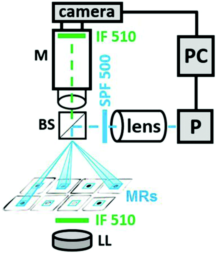 | ||
| Fig. 2 Block scheme of the experimental setup. Designations: M, microscope; P, a computer projector; IF 510, interference filters with λ = 510 nm, Δλ = 10 nm; LL, LED analysing light; SPF 500, a shortpass filter with the cut-off wavelength λ = 500 nm for actinic light; BS, a beam splitter with the reflection/transmission ratio equal to 50/50; lens, a condensing lens that focuses the light of the projector P on micro-reactors. Beams of actinic light generated by a dynamic mask of projector P (with the aid of LabVIEW software) are in blue. These beams create blue square frames around the micro-reactors (MRs), which mark the borders of the areas of illumination. The size of each blue square frame is about 0.5 mm × 0.5 mm. | ||
To place the MRs more compactly, we cut off small pieces of these slices in such a way that circular slices are transformed into square ones. Such square slices are filled with all the BZ reactants, sandwiched between two optical windows, and slightly pressed to make the MRs hermetically isolated from each other. After this pressing, the height of the MRs equals 0.44 mm. These MRs have no diffusive coupling.
The concentrations of the BZ reagents used in all micro-reactors are [MA] = 0.4 M, [Ru(bpy)3] = 0.7 mM, [ferroin] = 3 mM, [H2SO4] = 0.1 M, and [NaBrO3] = 0.3 M. These concentrations give a period T of oscillations of around 70 s. Oscillations last for approximately 110 minutes. During this time, the period increases slowly up to 120 s.
Pulsed illumination of each MR occurs through a dynamic mask at wavelengths λ < 500 nm (actinic light), where Ru(bpy)32+ absorbs intensively. The mask of the SLM is operated using LabVIEW software. At chosen concentrations of the BZ reactants, actinic light inhibits or even suppresses (at large enough light intensity) oscillations. Actinic incident light that illuminates MRs can be characterized by four values: (i) the area S of the light spot in the plane of MRs, (ii) light intensity I in the plane of MRs, (iii) duration of the pulses Δt, and (iv) time delays τ between a spike in one MR and a pulsed perturbation (induced by this spike) in the other MR.
Spots of the actinic light look like small squares that cover MRs completely; S = 500 × 500 μm2. In the CPG unit, which consists of four MRs, we implement unidirectional inhibitory coupling on the ring; when the kth oscillator (k = 9–12) receives a light pulse from the neighbouring oscillator on the ring, the light intensity Ik inside these spots can assume two values: 0 (which means no pulse of light) or Imax, where Imax (= 2.07 klx) is the maximum intensity of the projector. In the antenna unit, which consists of four MRs as well (k = 1–4), we also use unidirectional coupling on the ring, but with “negative” light pulses (a pulsed cut-off of the steady illumination).30 To transform the oscillatory BZ reaction into an excitable steady state (SS), we illuminate it continuously with light intensity ISS = 0.78 klx.
Excitable cells of the readers R and RA, and the DM unit are illuminated by constant light with the same intensity ISS, which is slightly above the threshold of a Hopf bifurcation. This light intensity creates BZ cells in the excitable SS. Each cell of the DM unit receives one “negative” light pulse from one cell of the R-unit and another pulse from a cell of the RA unit. To regulate the coupling strength between the MRs, which is determined by the product of light intensity and duration of the pulse, we vary the last one. For the CPG, the equality Ik = Imax is achieved during the time interval ΔtCPG, otherwise Ik = 0; for the A-unit, Ik = 0 during ΔtA, otherwise Ik = ISS = 0.78 klx; for cells of the R, RA, and DM units, Ik = ISS/2 for a single pulse and Ik = 0 for two simultaneous “negative” pulses during the time interval ΔtR (ΔtR = ΔtDM), otherwise Ik = ISS.
For inhibitory switching pulses from the DM to the CPG cells, we use the same computer projector. Note that the time intervals when the projector is used for different types of pulses (coupling and switching pulses) never overlap. The time delays τ(k)sw for switching pulses (which come to CPG cells #10–#12) were calculated using LabVIEW software as follows:
| τ(k)sw = (φ(k)sw − φk)Tm, | (1) |
| τ(k)sw = (1 + φ(k)sw − φk)Tm, | (2) |
Results
In this section, we experimentally study all the transitions between different modes of the CN. We consider different units of the CN, their combinations, and finally the entire CN.A. Antenna
The theoretical A-unit26 with a unidirectional pulse coupling consists of four identical excitable cells. Until now, this unit has not been studied experimentally. Our experimental A-unit with four excitable BZ cells is shown in Fig. 3(a). All the BZ cells in Fig. 3(a) are isolated diffusively and coupled by excitatory pulses of light. The regions illuminated by these pulses are marked by blue frames around small black circles in Fig. 3(a). Since we employ a photosensitive BZ reaction in which the light inhibits oscillations, we increase the intensity of constant light up to a value ISS, at which all the BZ oscillators of the A-unit are suppressed and the resulting steady state (SS) becomes excitable. Now, if we decrease the light intensity in a cell to a certain value Ip (Ip < ISS) for a short period of time Δt, a single spike is generated in this cell. We call such excitatory pulses “negative”.30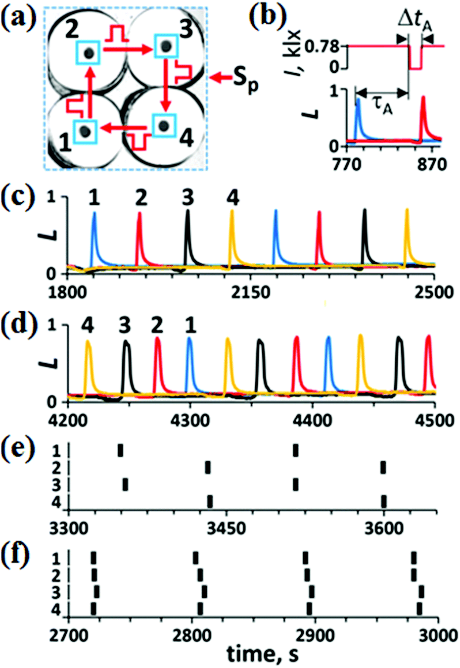 | ||
| Fig. 3 Antenna unit. (a) Blue squares around small black circles (which are four excitable BZ cells of the antenna unit) mark the areas of light pulses (500 × 500 μm2); Sp, external signals. (b) An example of excitatory unidirectional coupling of two neighboring oscillators #1 (blue curve) and #2 (red curve) by a “negative” light pulse (red line in the upper plot); τA = 65 s, ΔtA = 18 s, and ISS = 0.78 klx. Dynamic modes: (c) W, (d) WR, (e) AP, and (f) IP are obtained at τA = 65 s and ΔtA = 18 s for different initial conditions. Spikes of the AP and IP modes are presented by vertical bars to prevent spike overlapping that happens for conventional presentation like in panels (c) and (d). Numbers 1–4 in (c)–(f) correspond to indexes of the BZ micro-reactors. The amplitude of oscillations L is normalized in such a way that the maximum of L equals 1. | ||
In Fig. 3(b), we demonstrate the action of the “negative” pulse induced by a sharp spike in cell #1 (blue curve) on the neighboring cell #2 (red curve). After a time delay τA since the emergence of the spike, the light intensity I in cell #2 (red line, upper plot) becomes equal to 0 (Ip = 0) during the time interval ΔtA (we call the time delay τ and pulse duration Δt for pulses in the A-unit τA and ΔtA, respectively). This decrease in I induces a spike in cell #2. All neighboring cells in the A-unit are coupled unidirectionally by such “negative” pulses. Theoretically,26 there should be four main modes in such a network: W (walk), WR (walk-reverse), AP (anti-phase), and IP (in-phase). In Fig. 3(c)–(f), we present all these modes found experimentally under different initial conditions, which are moments of time when pulses Sp activate these or those excitable cells in the A-unit. The W-mode [Fig. 3(c)] is obtained by a perturbation of an arbitrary single cell by a “negative” pulse. The WR mode [Fig. 3(d)] is obtained by three consecutive “negative” pulsed perturbations of cells #1–#3 with a time interval of τA/3, but in the order reversed to the direction of coupling. The AP mode [Fig. 3(e)] is obtained by simultaneous perturbation of two diagonal cells. The IP mode [Fig. 3(f)] is obtained by simultaneous perturbation of all four cells by “negative” pulses.
Since the four stable modes that are realized in the A-unit depend on the initial perturbation, the antenna performs a function of associated memory. In other words, the antenna interprets external perturbations as one of these four stable modes.
B. Reader of the A-unit
A reader of the A-unit, RA, should recognize each of the four stable modes of the A-unit. Therefore, we set the RA unit to consist of four excitable cells tuned to one of the antenna modes [see Fig. 4(a) and (b)]. To distinguish the four stable modes of the A-unit, it was suggested25,26 to send excitatory pulses from each A-cell (with a specific phase shift) to each RA cell (with a specific threshold for excitation). This threshold is selected in such a way that the RA cell can generate a spike if four (or more) pulses come simultaneously. By the term “simultaneous pulses”, we mean the pulses that overlap in time or the pulses that have a small time interval between them (less than 5 s in our case). The cumulative effect of such pulses on the cell is that the cell “remembers” the effect of the first pulse at the moment of the arrival of the second pulse. | ||
| Fig. 4 Antenna and its reader. (a) BZ cells #5–#8 constitute the RA unit, while cells #1–#4 constitute the A-unit. Each cell of the RA unit receives two “negative” pulses, one from cell #1 and another from cell #2. Coupling of A-cells is not shown. Micro-reactors are depicted as small black circles. The intensity ISS of constant illumination of all the RA cells is equal to 0.78 klx (as for A-cells). (b) Scheme of the coupling of A and RA units. Black vertical bars represent spikes in A-cells for the IP, WR, AP, and W modes during a short period of time; circles represent cells #5–#8 of the RA unit. Only those links between the A and RA cells are drawn that lead to activation of the RA cells for a certain mode. The phase difference Δφ between cells #1 and #2 characterizes the corresponding modes in the A-unit. (c) Kinetics for the IP mode in the A-unit. Parameters of the coupling excitatory pulses in the A unit: τA = 90 s, ΔtA = 18 s. (d) Kinetics of all four cells of the RA unit for the IP mode in the A-unit. | ||
However, it turns out that it is enough for the mode recognition to send only two pulses from two neighboring A-cells, say, cells #1 and #2, to all RA cells provided that the threshold for excitation of these cells is equal to two simultaneous pulses [see Fig. 4(b)], i.e., with the amplitude of ISS/2 each. Cell #1 sends pulses immediately after its spike to all the RA cells, but pulses from cell #2 come to all the RA cells only after specific time delays, which are equal to the phase shift Δφ between spikes of cells #1 and #2 for specific modes [see Fig. 4(b)].
In Fig. 4(c) and (d), we exhibit an experiment on the recognition of the IP mode in the A-unit. In response to this mode [see Fig. 4(c)], only cell #5 tuned to the IP mode generates spikes [Fig. 4(d)]. In response to the WR, AP, and W modes in the A-unit, cells #6, #7, and #8, respectively, become active, while all the other cells remain in the SS.
The R-unit recognizes the modes of the CPG unit in exactly the same way as the RA unit recognizes the modes of the A-unit. The fact that the CPG cells are in the oscillatory state and are coupled via inhibitory pulses does not affect the process of recognition.
C. Mechanism of the DM unit and the entire CN
As we mentioned in the Introduction, the role of the DM unit is to compare the modes of the CPG and A-units and, if necessary, to switch the current CPG mode to a new one corresponding to the mode in the A-unit. Here, we demonstrate the functioning mechanism of the DM unit using the IP → AP transition as an example, since all the other transitions are performed in the same way.The block scheme of the CN for the IP → AP transition is presented in Fig. 5. The whole DM unit consists of 14 identical excitable cells #17–#30 with the excitation threshold equal to two simultaneous pulses, one of which comes from the RA unit and the other from the R-unit. The dynamics of the DM cells are exactly the same as the dynamics of the R and RA cells. In our case, the CPG is initially in the IP mode and, consequently, only cell #13 of the reader R (tuned to the IP mode) generates spikes. The A-unit is initially in the SS. After perturbation of the two diagonal cells of the A-unit by two external pulses, the AP mode is established in the A-unit. As a result, cell #7 (responsible for the AP mode) starts generating spikes. Simultaneous pulses from cells #13 and #7 activate the one cell in the DM unit, cell #17 in our case.
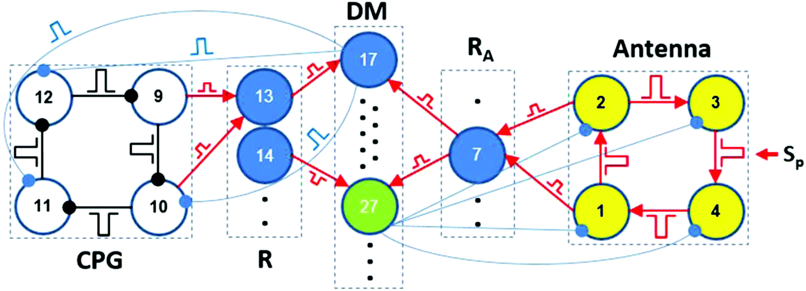 | ||
| Fig. 5 Block scheme of the CN for the IP → AP transition (only cells participating in the IP → AP transition are drawn). Inhibitory pulses are marked by connectors with small circles at the end, while connectors for excitatory pulses are marked by arrows. Blue circles #13–#16 are cells of the R unit. Blue circles #5–#8 are cells of the RA unit. Cells #17–#30 belong to the DM unit. Green circles #27–#30 are excitable cells that are used for returning the A-unit to its initial steady state, i.e., to deactivate the A cells after fulfilling the task, while blue cells #17–#26 are used for switching the modes of the CPG. Black dots mark hidden MRs. | ||
Cell #17 in turn should send switching inhibitory pulses to cells of the CPG to perform the IP → AP transition. Each cell of the DM unit has a specific task to fulfill this or that transition between the modes of the CPG. In general, each DM cell (from #17 to #26) sends three inhibitory pulses to cells #10, #11, and #12. These switching pulses have identical amplitudes, but arrive at the CPG cells at special phases φ(k)sw of the oscillatory cycle, where k is the index of the CPG cell. Different phases φ(k)sw are needed to shift CPG spikes by specific values Δφk required for a desired mode transition.
To find the phases φ(k)sw, we use phase response curves (PRCs) for the CPG oscillators and our previous data on controllable switching between CPG modes.23,24,26 These data allow us to calculate approximate phases and phase shifts Δφk needed to fulfill the transition. Internal pulses that couple neighboring CPG oscillators largely affect the needed phase shifts Δφk making them smaller or larger. To correct approximate phases and durations of switching pulses, we performed additional experiments. The final list of all required phases φ(k)sw and pulse durations Δt(k)sw is given in Table S.1 (ESI†). In accordance with Table S.1 (ESI†), cells #10 and #12 of the CPG should receive pulses at the same phases φ(10)sw = φ(12)sw = 0.7 to perform the IP → AP transition.
After the IP → AP transition, cell #14 in the R-unit (tuned to the AP mode) starts generating spikes. Then, both active cells #14 and #7 activate the excitable cell #27 in the DM unit, which, in turn, sends inhibitory pulses to all the cells of the A-unit, thus suppressing and returning them to the initial SS.
D. Testing a hybrid CN
For the trial experimental implementation of the proposed mechanism of the entire CN, we have used four BZ cells for the CPG unit, four other BZ cells for the A-unit, and electronic units R-, RA, and DM [see Fig. 6(a)]. The circuits of the electronic units built with the aid of LabVIEW software31 are presented elsewhere.24 These units imitate actions of the real (made of excitable BZ cells) R, RA, and DM units. The cells of these units work as logical elements “AND”. When two input pulses arrive simultaneously to such an electronic cell [see Fig. 6(b)], it generates one (as cells of the R and RA units) or even three (as most cells of the DM unit) outgoing pulses. One input pulse or two non-simultaneous pulses cannot generate the output pulse. The DM cells send inhibitory pulses with time delays τ(k)sw such that these pulses arrive at the CPG cells at phases φ(k)sw presented in Table S.1 (ESI†). All outgoing pulses of electronic cells of the R- and RA units have zero-time delays. The hybrid CN shown in Fig. 6(a) performs all the transitions between the modes of the CPG that are induced by the modes of the A-unit.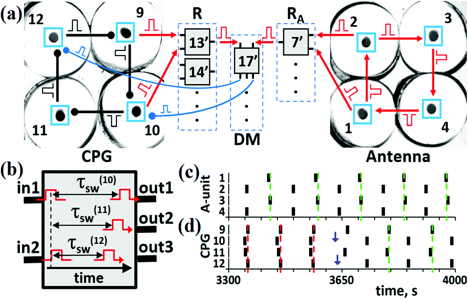 | ||
| Fig. 6 The hybrid CN. (a) Block-scheme of the hybrid CN consisting of chemical units (Antenna and CPG) and electronic units (R, DM, and RA). Electronic cells #13′, #14′, #7′, and #17′ correspond to cells #13, #14, #7, and #17, respectively, in Fig. 5. (b) Description of pulse generation in an electronic cell of the DM unit. Output 2 is not used in cell #17′. Vertical dashed line indicates that two incoming pulses “in1” and “in2” are overlapped. These overlapped pulses trigger two outgoing pulses with time delays τ(10)sw and τ(12)sw with durations Δtsw. (c) Kinetics for the AP mode in the A-unit at τA = 40 s and ΔtA = 18 s. (d) Kinetics of the IP → AP transition in the CPG. Vertical blue arrows mark moments of time when switching pulses arrive at cells #10 and #12. Parameters for pulses in the CPG: τCPG = 10 s and ΔtCPG = 7 s. Parameters for the switching pulses: τ(10)sw = 52 s, τ(12)sw = 60 s, φ(10)sw = φ(12)sw = 0.7, and Δtsw = 8 s. In panels (c) and (d), red and green vertical dashed lines mark moments of time when the IP and AP modes, respectively, are recognized by readers. | ||
An example of the IP → AP transition in the CPG induced by the AP mode in the A-unit [shown in Fig. 6(c)] is presented in Fig. 6(d). First, the R and RA units should recognize the modes in the CPG and A-unit, respectively, i.e., cells #13′ and #7′ should be activated. Then, output pulses of these excited cells should occur at the same time to arrive simultaneously at cell #17′ (since there are no time delays for output pulses sent by R- and RA-cells). The probability of simultaneity of the output pulses from cells #13′ and #7′ depends on the difference between frequencies of the dynamic modes in the CPG and A-unit, and on the duration of pulses ΔtR and ΔtDM sent to and from the R and RA units, respectively. As can be seen in Fig. 6(c) and (d), simultaneous spikes of the A and CPG cells take place in the time interval between t ≅ 3560 s and t ≅ 3575 s. As a result, two simultaneous pulses activate cell #17′, which in turn generates two inhibitory pulses and sends them to the BZ micro-cells, one pulse to cell #10 and another to cell #12 with the time delays corresponding to the IP → AP transition (see Table S.1 in the ESI†). The moments of their arrival to cells #10 and #12 are marked by blue vertical arrows in Fig. 6(d). As a result of these switching pulses, the AP mode emerges in the CPG and is recorded by cell #14′ of the R-unit [green vertical dashed lines in Fig. 6(d)].
All other transitions, i.e., IP → W, IP → WR, AP → IP, AP → W, AP → WR, W → IP, W → AP, WR → IP, and WR → AP, are presented in the ESI.†
The case in which not only the CPG and A-unit, but the DM unit as well are represented by real BZ MRs, while the R and RA units remain electronic circuits (LabVIEW software) has been realized for the IP → AP transition (as an example) and is presented in the ESI.† Since all our tests of the hybrid CN are successful, we can start working with a BZ CN that has no electronic units.
E. “Pure” BZ CN
Our “pure” CN consists of BZ MRs only, but light pulses are controlled electronically, as before. To test experimentally the efficiency of this CN, we arbitrarily select the IP → AP transition. For this case, the CN contains 13 BZ MRs, as shown in Fig. 5 and 7(a). The role of each MR in the whole CN is determined by light pulses and by constant illumination of some MRs. Since all these effects of light on the MRs are realized using a computer projector and software, a MR can perform any role regardless of its physical location. The numbering and pulse coupling between MRs in Fig. 7(a) correspond to the numbering and pulse coupling for the theoretical cells in Fig. 5.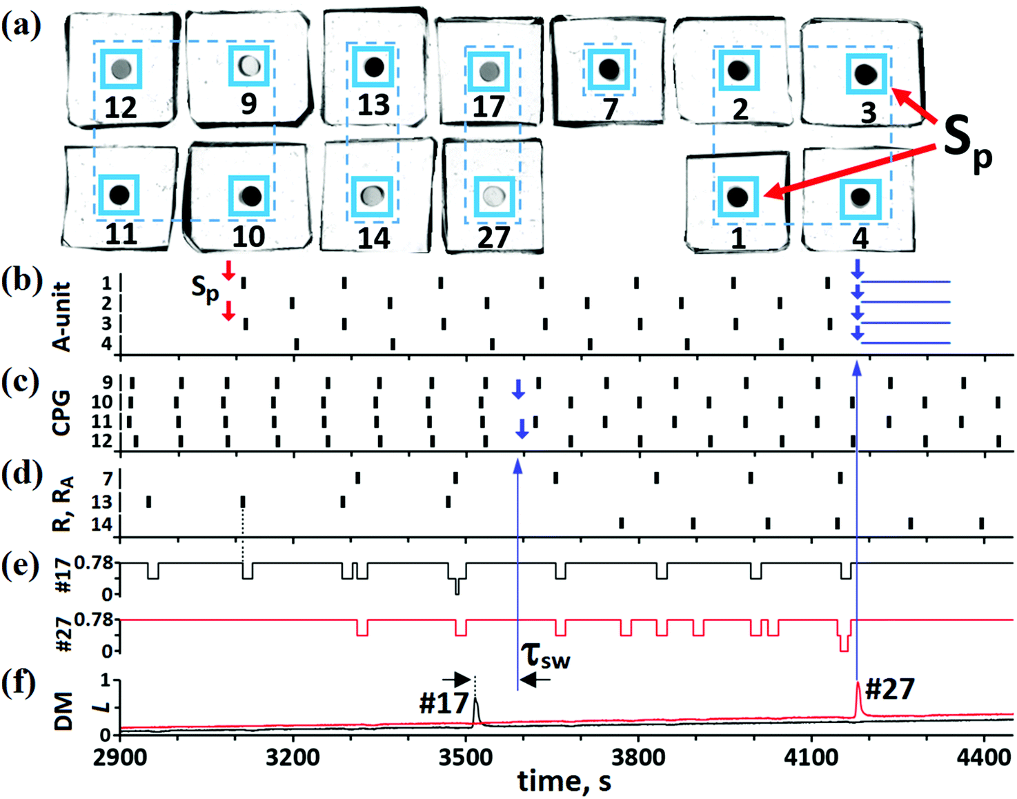 | ||
| Fig. 7 “Pure” chemical BZ CN. (a) BZ micro-cells (small black circles) used for the IP → AP transition. Cells #1–4 constitute the A-unit; cell #7 is the RA-unit; cells #9–12 are the CPG unit; cells #13 and #14 are the R-unit; cells #17 and #27 are the DM unit; Sp are external pulses with Δtsp = 25 s. (b) Kinetics for the A-cells. Two small red arrows mark the moment of time when signals Sp initiate spikes in cells #1 and #3. Parameters for the inner excitatory pulses: τA = 60 s and ΔtA = 25 s. Four small blue arrows mark the moment of time when suppressing pulses from DM cell #27 arrive at the cells of the A-unit. The duration ΔtSS of these pulses is marked by four horizontal blue segments, ΔtSS = 160 s. (c) Kinetics of the CPG. Parameters for the inner inhibitory pulses: τCPG = 8 s and ΔtCPG = 7 s. For the IP mode, TIP = 91 s, while for the AP mode, TAP = 126 s. Two small blue arrows mark the moments of time when switching pulses (with duration Δtsw = 8 s) from the DM cell #17 arrive at cells #10 and #12. (d) Kinetics of the cells belonging to the R and RA units. Duration of the pulses ΔtR that arrive at the cells of the R and RA units from CPG cells and A-cells, respectively, is equal to 18 s. (e) “Negative” pulses of light (with duration ΔtDM = 18 s) generated by the R and RA cells and arriving at DM cells #17 (black line) and #27 (red line). (f) Kinetics of cells #17 and #27. Time delays τ(10)sw and τ(12)sw (marked as “τsw”) between a spike in cell #17 and pulses generated by this cell are equal to 75 s and 82 s, respectively. | ||
At the initial moment of time, the A-unit is in the SS [see Fig. 7(b)], while the CPG is in the IP mode [see Fig. 7(c)]. This IP mode induces spikes in MR #13 [see Fig. 7(d)], but with half the frequency of the IP oscillations in the CPG. Such period doubling of MR #13 oscillations is explained by the fact that there is not enough time for this cell to return to its initial excitable SS for the period of the IP oscillations. At some moment of time, external signals Sp initiate AP oscillations in the A-unit [see Fig. 7(b)]. The AP mode of the A-unit induces spikes in BZ cell #7 [see Fig. 7(d)] belonging to the RA unit. Thus, the activity of BZ MRs #13 and #7 indicates the IP mode in the CPG and AP mode in the A-unit, respectively.
For the IP → AP transition to occur, cell #17 in the DM unit must be activated. Activation of cell #17 happens when it receives two simultaneous pulses, one from MR #13 and another from MR #7. Almost simultaneous spikes in cells #13 and #7 take place at t ≅ 3470–3485 s and the simultaneous arrival of pulses from these two cells at MR #17 occurs at t ≅ 3485 s [see Fig. 7(e)]. The last event initiates a spike in MR #17 [see Fig. 7(f)]. Note that initiation of this spike is analogous to the logical operation “AND”. In turn, the spike in cell #17 generates inhibitory pulses (with different time delays τ(10)sw = 75 s and τ(12)sw = 82 s since the IP mode is not ideal) that are directed to cells #10 and #12 (see the blue arrow in Fig. 7(f) to (c) at t = 3590). As given in Table S.1 (ESI†), these switching pulses should arrive at cells #10 and #12 at phases φ(10)sw = φ(12)sw = 0.7. Two small blue arrows in Fig. 7(c), marking the moments of time when these two pulses start perturbing the phases of micro-oscillators #10 and #12, correspond perfectly to the expected phases. As can be seen in Fig. 7(c), at t > 3600 s, the two switching pulses transform the IP mode to the AP mode. After the emergence of the AP mode in the CPG, cell #14 in the R-unit starts generating spikes, while cell #13 stops oscillating [see Fig. 7(d)].
Note that time delays τ(10)sw and τ(12)sw used in the present case of the BZ CN are larger than the same time delays used in the case of the hybrid CN. This is explained by the fact that chemical R and RA units work more slowly than the electronic units and the DM cell #17 generates its own spike and the corresponding switching pulses much later than in the case of the electronic DM unit.
In the last stage of the IP → AP transition, the CN should automatically return all cells of the A-unit to their original steady state. This operation is fulfilled with the aid of cell #27, which is activated (at t ≅ 4185 s) by two simultaneous pulses from cells #7 and #14 [see red line in Fig. 7(e) and (f)]. The spike in cell #27 generates four inhibitory pulses that are sent to all MRs of the A-unit [see the big blue vertical arrow in Fig. 7(f) to (b)]. These pulses [the durations of which are marked by four horizontal segments in Fig. 7(b)] suppress the activity of A-cells and return them all to the SS. We can conclude this section by stating that the IP → AP transition in the CPG is carried out automatically soon after the emergence of the AP mode in the A-unit.
Conclusions
We have demonstrated experimentally that a network of BZ MRs can behave reasonably. A similar behavior of living creatures is called intelligence. Thus, we show that “intelligence could be a product of the interaction of non-intelligent parts”.17 Our first CN is rather simple. For example, it cannot really “think”. Also, it is rather big since it involves a computer projector and a computer itself to control light pulses and the intensity of illumination in some specific MRs. There are some other small drawbacks that appear during the experiment. For example, our CN is rather slow, if we use a relatively slow BZ reaction as a chemical oscillator. But, let us remember that this is the first chemical, or more correctly opto-chemical, neurocomputer. It performs the task of adaptation to the environment.The ways to improve the CN are evident. Light pulses should be replaced by chemical BZ waves that propagate along narrow channels connecting the BZ micro-reactors. Their lengths will determine the time delays. With chemical waves, our CN will be completely “chemical” without the use of electricity and will be really small, around 1 mm. To make the CN a “thinking” device, we should teach it to choose between the different ways that may exist for solving a problem. To accelerate the rate of the CN, we should find chemical micro-oscillators that are faster than the BZ reaction. Note also that our CN can be much more complex and perform more sophisticated operations due to increasing the number N of MRs. An increase in N should not increase (at least noticeably) the time needed to complete the task since all operations are carried out in parallel.
The batch MRs used in the present work can be replaced by small (around 100 μm in diameter) beads with the immobilized BZ catalyst,29,32 which are immersed in a bath of a catalyst-free BZ solution. In such a system, the CN will be able to work for a very long time, ideally forever. Note that the architecture of our CN allows us to use any oscillators, for example, mechanical or electrochemical ones, neurons or oscillatory micro-crystals, since the general schemes shown in Fig. 1 or 5 do not impose restrictions on the nature of the oscillators.
If we connect chemical oscillations in the CPG with its probable mechanical movement,33 we can obtain a smart micro-device that has different gaits depending on the CPG mode. The interaction of several such micro-devices can provide a new intriguing direction in the study of the collective behavior of intelligent “chemical creatures”.
Conflicts of interest
There are no conflicts to declare.Acknowledgements
V. K. V. and I. S. P. are grateful to the Russian Academic Excellence Project at the Immanuel Kant Baltic Federal University.Notes and references
- I. R. Epstein, Science, 2007, 315, 775–776 CrossRef CAS PubMed.
- Collision based computing, ed. A. Adamatzky, Springer, 2003 Search PubMed.
- Reaction–Diffusion Computers, ed. A. Adamatzky, B. Costello and T. Asai, Elsevier, Amsterdam, 2005 Search PubMed.
- From Parallel to Emergent Computing, ed. A. Adamatzky, S. Akl and G. Ch. Sirakoulis, CRC Press, Taylor & Francis Group, LLC, Boca Raton, FL, 2019 Search PubMed.
- O. Steinbock, P. Kettunen and K. Showalter, J. Phys. Chem., 1996, 100, 18970–18975 CrossRef CAS.
- A. Grama, A. Gupta, G. Karypis and V. Kumar, Introduction to parallel computing, Addison-Wesley Professional, 2nd edn, 2003 Search PubMed.
- B. P. Belousov, in Collection of Short Papers on Radiation Medicine, Medgiz, Moscow, 1959, pp. 145–152 Search PubMed.
- A. M. Zhabotinsky, Proc. Acad. Sci. USSR, 1964, 157, 392–395 Search PubMed.
- J. Gorecki, K. Yoshikawa and Y. Igarashi, J. Phys. Chem. A, 2003, 107, 1664–1669 CrossRef CAS.
- A. Kaminaga, V. K. Vanag and I. R. Epstein, Angew. Chem. Int. Ed., 2006, 45, 3087–3089 CrossRef CAS PubMed.
- J. Gorecki, J. N. Gorecka and A. Adamatzky, Phys. Rev. E: Stat., Nonlinear, Soft Matter Phys., 2014, 89, 042910 CrossRef CAS PubMed.
- J. Gorecki, K. Gizynski, J. Guzowski, J. Gorecka, P. Garstecki, G. Gruenert and P. Dittrich, Philos. Trans. R. Soc. London, Ser. A, 2015, 373, 20140219 CrossRef PubMed.
- G. Bostock, Programmable Logic Devices: Technology and Applications, McGraw-Hill, 1988 Search PubMed.
- C. Grebogi, E. Ott and J. A. Yorke, Science, 1987, 238, 632–638 CrossRef CAS PubMed.
- J. Milnor, Commun. Math. Phys., 1985, 99, 177–195 CrossRef.
- U. Feudel, A. N. Pisarchik and K. Showalter, Chaos, 2018, 28, 033501 CrossRef PubMed.
- M. Minsky, The Society of Mind, Simon & Schuster, New York, 1986 Search PubMed.
- R. J. Field and M. Burger, Oscillations and Traveling Waves in Chemical Systems, ed. R. J. Field, M. Burger, Wiley, New York, 1985 Search PubMed.
- S. Kádár, T. Amemiya and K. Showalter, J. Phys. Chem. A, 1997, 101, 8200–8206 CrossRef.
- G. Buzsaki, Neuron, 2010, 68, 362–385 CrossRef CAS PubMed.
- V. K. Vanag, P. S. Smelov and V. V. Klinshov, Phys. Chem. Chem. Phys., 2016, 18, 5509–5520 RSC.
- P. S. Smelov and V. K. Vanag, Russ. J. Phys. Chem. A, 2017, 91, 1015–1020 CrossRef CAS.
- P. S. Smelov, I. S. Proskurkin and V. K. Vanag, Phys. Chem. Chem. Phys., 2019, 21, 3033–3043 RSC.
- I. S. Proskurkin, P. S. Smelov and V. K. Vanag, ChemPhysChem, 2019, 20, 2162–2165 CrossRef CAS PubMed.
- P. S. Smelov and V. K. Vanag, R. Soc. Open Sci., 2018, 5, 171495 CrossRef PubMed.
- V. K. Vanag, Chaos, 2019, 29, 083104 CrossRef PubMed.
- A. F. Taylor, M. R. Tinsley and K. Showalter, Phys. Chem. Chem. Phys., 2015, 17, 20047–20055 RSC.
- N. Tompkins and S. Fraden, Am. J. Phys., 2016, 84, 150–158 CrossRef PubMed.
- J. F. Totz, J. Rode, M. R. Tinsley, K. Showalter and H. Engel, Nat. Phys., 2018, 14, 282 Search PubMed.
- I. S. Proskurkin and V. K. Vanag, Phys. Chem. Chem. Phys., 2015, 17, 17906–17913 RSC.
- LabVIEW, http://https:/www.ni.com/en-us.html, 2020.
- I. L. Mallphanov and V. K. Vanag, J. Phys. Chem. A, 2020, 124, 272–282 CrossRef CAS PubMed.
- I. R. Epstein, V. K. Vanag, A. C. Balazs, O. Kuksenok, P. Dayal and A. Bhattacharya, Acc. Chem. Res., 2012, 45, 2160–2168 CrossRef CAS PubMed.
Footnote |
| † Electronic supplementary information (ESI) available: Table and figures that provide more details about the results. See DOI: 10.1039/d0cp01858a |
| This journal is © the Owner Societies 2020 |