
 Open Access Article
 This Open Access Article is licensed under a Creative Commons Attribution-Non Commercial 3.0 Unported Licence
Kinetic modelling of intraband carrier relaxation in bulk and nanocrystalline lead-halide perovskites†
Thomas R.
Hopper‡
 a,
Ahhyun
Jeong‡
a,
Andrei A.
Gorodetsky‡
a,
Franziska
Krieg
bc,
Maryna I.
Bodnarchuk
bc,
Xiaokun
Huang
d,
Robert
Lovrincic
d,
Maksym V.
Kovalenko
bc and
Artem A.
Bakulin
*a
a,
Ahhyun
Jeong‡
a,
Andrei A.
Gorodetsky‡
a,
Franziska
Krieg
bc,
Maryna I.
Bodnarchuk
bc,
Xiaokun
Huang
d,
Robert
Lovrincic
d,
Maksym V.
Kovalenko
bc and
Artem A.
Bakulin
*a
aUltrafast Optoelectronics Group, Department of Chemistry, Imperial College London, London W12 0BZ, UK. E-mail: a.bakulin@imperial.ac.uk
bLaboratory of Inorganic Chemistry, Department of Chemistry and Applied Biosciences, ETH Zurich, Vladimir-Prelog-Weg 1-5/10, 8093 Zurich, Switzerland
cLaboratory for Thin Films and Photovoltaics, Empa – Swiss Federal Laboratories for Materials Science and Technology, Überlandstrasse 129, CH-8600 Dübendorf, Switzerland
dInstitute for High-Frequency Technology, Technische Universität Braunschweig, Schleinitzstrasse 22, 38106, Braunschweig, Germany
First published on 22nd July 2020
Abstract
The relaxation of high-energy “hot” carriers in semiconductors is known to involve the redistribution of energy between hot and cold carriers, as well as the transfer of energy from hot carriers to phonons. Over the past few years, these two processes have been identified in lead-halide perovskites (LHPs) using ultrafast pump–probe experiments, but their interplay is not fully understood. Here we present a practical and intuitive kinetic model that accounts for the effects of both hot and cold carriers on carrier relaxation in LHPs. We apply this model to describe the dynamics of hot carriers in bulk and nanocrystalline CsPbBr3 as observed by multi-pulse “pump–push–probe” spectroscopy. The model captures the slowing of the relaxation dynamics in the materials as the number of hot carriers increases, which has previously been explained by a “hot-phonon bottleneck” mechanism. The model also correctly predicts an acceleration of the relaxation kinetics as the number of cold carriers in the samples is increased. Using a series of natural approximations, we reduce our model to a simple form containing terms for the carrier–carrier and carrier–phonon interactions. The model can be instrumental for evaluating the details of carrier relaxation and carrier–phonon couplings in LHPs and other soft optoelectronic materials.
1. Introduction
Lead-halide perovskites (LHPs) are rapidly emerging as a promising class of semiconducting material for future optoelectronic applications. Since the first report of 3.8% power conversion efficiency (PCE) in 2009,1 laboratory-scale LHP solar cells can now routinely achieve PCEs above 20%, with a record PCE over 25%.2 Compared to the top PCEs of other third-generation solution-processable photovoltaic materials, this value is impressively close to the ∼33% PCE given by the theoretical “Shockley–Queisser” limit for single-junction solar cells.3 A key factor underpinning this limit is the rapid dissipation of energy from “hot” carriers following the photoexcitation of the semiconductor above its bandgap. Early work by Ross and Nozik postulated that the performance of a solar cell could be dramatically enhanced if the hot carriers could be utilised.4 The efficiency of this utilisation depends on how quickly the hot carriers dissipate their excess energy, reflected by the relaxation rate.The intraband relaxation rate depends on many factors which control the carrier dynamics, including the interaction between carriers (i.e. redistribution of heat between the carriers, called thermalisation), and the interactions between carriers and phonons (i.e. the removal of excess energy through lattice vibrations, called cooling).5 Cooling has been studied extensively in LHPs using pump–probe methods. A common finding is a slowdown of the cooling kinetics with increasing carrier density.6–12 This phenomenon has also been observed in traditional semiconductors such as GaAs,13,14 and is often referred to as the “hot-phonon bottleneck”. For LHPs, this behaviour is thought to occur when polarons (i.e. localised distortions of the lattice surrounding a carrier) spatially overlap, leading to the reabsorption of hot phonons by adjacent carriers.15 We previously demonstrated that this behaviour in LHPs is sensitive to the material composition, and is particularly pronounced in the all-inorganic CsPbBr3 compared to its hybrid counterparts with vibrationally active organic cations.16
Most commercially available transient absorption methods do not have the prerequisite time resolution to observe thermalisation, but high-resolution two-dimensional electronic spectroscopy has been employed to demonstrate this effect in LHPs.17,18 These studies show that the high-energy carriers produced by above-gap excitation reach a thermal distribution through carrier scattering at the early stage of relaxation (<100 fs), followed by the carrier–phonon interactions where the heat is dissipated in the lattice (∼500 fs). These reports provide valuable mechanistic insights, but the methods lack the ability to distinguish the roles of the hot and cold carriers on carrier relaxation.
Here, we propose a practical kinetic model to describe the effects of the hot and cold carrier populations on the carrier relaxation kinetics in CsPbBr3 bulk and nanocrystal (NC) films, and apply this model to explain the results of “pump–push–probe” measurements.19 Our results convey two competing pathways for the dissipation of the excess hot carrier energy into either optical phonons or cold carriers. By applying simple approximations, we reduce this model into a single intuitive equation containing terms for the carrier–carrier and carrier–phonon interactions. At sufficiently high cold carrier concentration, the interactions between hot and cold carriers dominate over the hot-phonon bottleneck behaviour, leading to accelerated carrier relaxation.
2. Experimental methods
2.1 Sample preparation
CaF2 substrates (12 mm diameter, 1 mm thickness, EKSMA Optics) were first treated with O2 plasma to improve wetting.The bulk CsPbBr3 films were prepared by dissolving 1![[thin space (1/6-em)]](https://www.rsc.org/images/entities/char_2009.gif) :1 mole ratio of PbBr2 (Alfa Aesar, 99.9%) and CsBr (Alfa Aesar, 99.9%) in dimethyl sulfoxide (Sigma-Aldrich, 99.9%) with concentration of 0.4 M and stirring at 50 °C overnight. Afterwards, ∼35 μl of the as-prepared solution was dropped onto the substrate and spin-coated at 3000 rpm for 2 min. The solvent extraction method was then applied by using 300 μl chloroform after 1 min spinning.20,21 The as-formed thin films were then thermally annealed on a hot plate at 100 °C for 10 min inside the glovebox.
:1 mole ratio of PbBr2 (Alfa Aesar, 99.9%) and CsBr (Alfa Aesar, 99.9%) in dimethyl sulfoxide (Sigma-Aldrich, 99.9%) with concentration of 0.4 M and stirring at 50 °C overnight. Afterwards, ∼35 μl of the as-prepared solution was dropped onto the substrate and spin-coated at 3000 rpm for 2 min. The solvent extraction method was then applied by using 300 μl chloroform after 1 min spinning.20,21 The as-formed thin films were then thermally annealed on a hot plate at 100 °C for 10 min inside the glovebox.
The CsPbBr3 NCs were synthesised according to a previously reported method.22 1 mL lead-oleate (0.5 M in 1-octadiene (ODE)), 0.8 mL Cs-oleate (0.4 M in ODE), 0.0445 g of N,N-(dimethyloctadecylammonio)-propanesulfonate and 10 mL ODE were added to a 25 mL three-neck flask and heated to 130 °C under vacuum. As soon as the reaction temperature was reached, the atmosphere was changed to nitrogen and 0.42 g of oleylammonium bromide, dissolved in 3 mL of toluene, was injected. The reaction mixture was immediately cooled to room temperature by means of an ice bath.
The crude solution was then centrifuged at 29500 g for 10 min. The precipitate was discarded and ethylacetate (30 mL) was added to the supernatant (ca. 15 mL). The mixture was centrifuged at 29500 g for 10 min and the precipitate was dispersed in toluene (3 mL). This solution was subjected to three additional rounds of precipitation with ethylacetate (6 mL) and centrifugation at 29500 g for 1 min and subsequent redispersion using toluene (3 mL). All films were determined to be ∼300 nm thick by UV-vis ellipsometry.
2.2 UV-vis spectroscopy
In order to determine the carrier density induced by the pump, the absorption cross section of the samples was calculated from the linear absorption spectra. These spectra were obtained from a UV-vis spectrometer (Shimadzu 2600, equipped with an ISR-2600Plus integrating sphere). A 1 nm sampling interval was used with a 5 nm slit width.2.3 Ultrafast infrared differential transmission measurements
A Ti:sapphire regenerative amplifier (Astrella, Coherent) was used to pump two optical parametric amplifiers (TOPAS-Prime, Coherent) with 1.55 eV pulses at a repetition rate of 4 kHz and pulse duration of ∼35 fs. The signal output (∼0.95 eV) of one of the optical parametric amplifiers was directed into a β-barium borate crystal (EKSMA Optics) along with the residual part of the fundamental (1.55 eV) from the regenerative amplifier. Sum frequency generation yielded the 2.5 eV ∼60 fs pump pulse. The idler output (0.6 eV, ∼50 fs) of the other optical parametric amplifier was split in a 9:1 ratio. The more intense portion was used as the push, and the weaker portion was used as the probe. The pump and probe beams were collinearly overlapped and focused onto a ∼0.2 mm diameter spot on the sample. The push was focused onto the same spot less tightly (0.4 mm) in a non-collinear (∼5°) geometry with respect to the pump/probe. Beam diameters were confirmed with pinholes. The transmission of the probe through the sample was recorded with an amplified PbSe photodetector (PDA20H-EC, ThorLabs). This was connected to a lock-in amplifier (SR-830, Stanford Research Systems) coupled to a chopper in the pump beam. The chopper operated at half the repetition rate of the amplifier to block every other pump pulse. The delay between the pump, push and probe beams were controlled with mechanical delay stages. The sample was measured in a nitrogen-purged quartz cuvette.
3. Experimental results
The linear absorption spectra of the bulk and NC samples are shown in Fig. 1(a). As expected, the NC sample exhibits a slightly blueshifted absorption onset due to weak quantum confinement.23 The NCs studied here have a cubic shape and an average edge-length of 8 ± 2 nm, as confirmed by the electron micrograph in the inset of Fig. 1(a). A more lengthy discussion of the material properties of the two samples is given elsewhere.19 Taking together the weak confinement and ordered packing of the NCs, we anticipate that carriers can move within and between NCs. The high mobility of carriers in films of similarly sized CsPbBr3 NCs was recently demonstrated by optical pump-terahertz probe experiments.24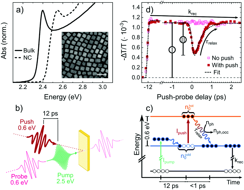 | ||
| Fig. 1 (a) UV-Vis absorption spectra of bulk and NC CsPbBr3 thin films. Inset: High-angle annular dark field scanning transmission electron micrograph of the ∼8 nm edge length NCs; scale bar = 20 nm. (b) Pulse sequence. The pump and probe are co-linear. (c) Three-level model used to interpret (d) the differential probe transmission (for the NC sample) in response to the pump and push pulses. ncold0 = 1.1 × 1017 cm−3, nhot0 = 5.8 × 1016 cm−3. | ||
To investigate the intraband relaxation dynamics in the samples, we used a “visible pump–IR push–IR probe” pulse sequence, which has been outlined in previous works.16,19,25,26 and recently adapted to study hot carrier extraction in LHPs.27 As depicted in Fig. 1, a 2.5 eV pump generates excited carriers which promptly relax to the band edges. These free carriers are monitored by the differential transmission of a near-IR probe at 0.6 eV, which corresponds to an intraband absorption in LHPs.28–30 After a fixed delay (12 ps), an intense 0.6 eV push pulse converts the cold carriers into hot carriers, which is observed as a bleaching of the differential transmission signal. As the hot carriers relax, the pump–probe signal recovers. We fit the recovery of the probe signal with a monoexponential curve to extract the relaxation time, τrelax. The intensity of the pump and push pulses are used to control the cold and hot carrier densities, respectively. The representative fluence-dependent pump–probe decay kinetics in Fig. S1 (ESI†) are not purely exponential, which is suggestive of free carrier as opposed to monomolecular exciton recombination.
The total number of (hot and cold) carriers per unit volume in the system, nexc, is calculated using eqn (1). Einc is the incident energy per pump pulse, A is the absorbance of the sample at the pump photon energy Eexc, R is the beam radius and d is the sample thickness.
 | (1) |
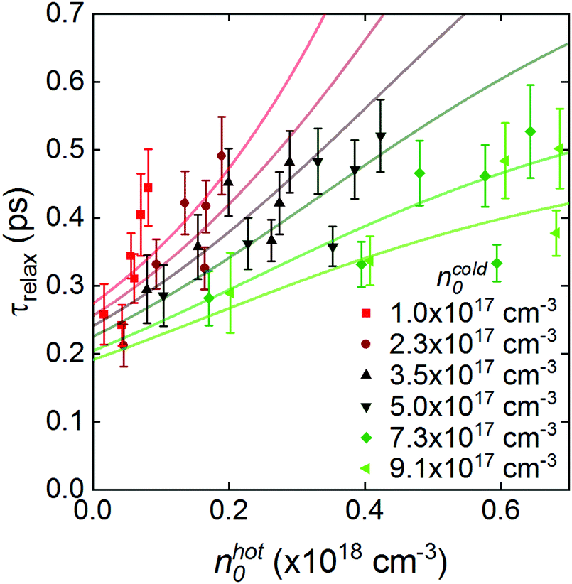
The initial hot carrier density, nhot0, can be obtained from the product of nexc and the ratio between the amplitudes of the push-induced bleach and the signal before the arrival of the push pulse, labelled II and I in Fig. 1(d). The dependence of τrelax on the initial density of the hot and cold carriers is outlined in Fig. 2. For a given value of ncold0 (cold carrier density just before the push), we find that τrelax increases with nhot0. These dynamics agree with the literature6–12 and our own previous findings which invoke the hot-phonon bottleneck effect.16,19 Interestingly, we also find that τrelax tends to decrease with increasing nexc, suggesting that the hot-phonon bottleneck plays a lesser role in intraband relaxation when there are many cold carriers in the system. From this, we can deduce that the carrier relaxation occurs via at least two competing pathways. When there are few cold carriers, carrier–phonon interactions dominate over the hot-cold carrier interactions, and the hot-phonon bottleneck primarily governs the relaxation dynamics. At higher cold carrier density, relaxation via carrier–carrier interactions starts to dominate, resulting in the overall faster relaxation and the reduced impact of the hot-phonon bottleneck.19
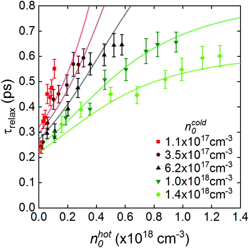 | ||
| Fig. 2 Plot of relaxation time with respect to the hot carrier density directly after the push (nhot0) and cold carrier density just before the push (ncold0) in the CsPbBr3 NCs. Points are taken from the experimental data and the solid lines are fits generated from the model described in Section 4. | ||
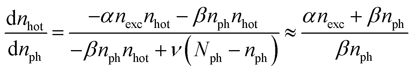
4. Kinetic modelling
We interpret our experimental data as the relaxation of hot carriers in the LHP samples through carrier–carrier and/or carrier–phonon interactions. To gain more insight into the interplay between these processes, we have developed a numerical model describing each process that is eventually reduced to a single equation, shown later. To fully describe the data, we take the following approximations:• For simplicity, and based on the small binding energies and comparable effective masses of electrons and holes,31 we ignore exciton effects and assume that electrons and holes exhibit similar behaviour;
• Carriers can be either hot or cold, hence the sum of the number of hot and cold carriers (nhot and ncold) is equal to the total number of carriers (nexc);
• Here, hot carriers have an excess energy of ∼0.6 eV, comparable to the push energy. Just before the push arrives, nhot is negligible;
• Carrier relaxation involves two co-existing pathways, each with characteristic rates; (i) carrier–carrier interaction, when a hot carrier scatters with other hot or cold carriers and loses (some of) its excess energy; and (ii) carrier–phonon interaction, when the excess energy is transferred into an unoccupied phonon mode. The phonon mode becomes occupied, and the carrier relaxes;
• Total number of phonon modes (Nph) is a constant for the material. The modes can be either occupied or unoccupied.
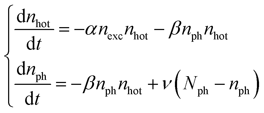
All simulations are presented for the unit volume (cm−3). The initial system of equations is shown in eqn (2) with the initial conditions shown in eqn (3):
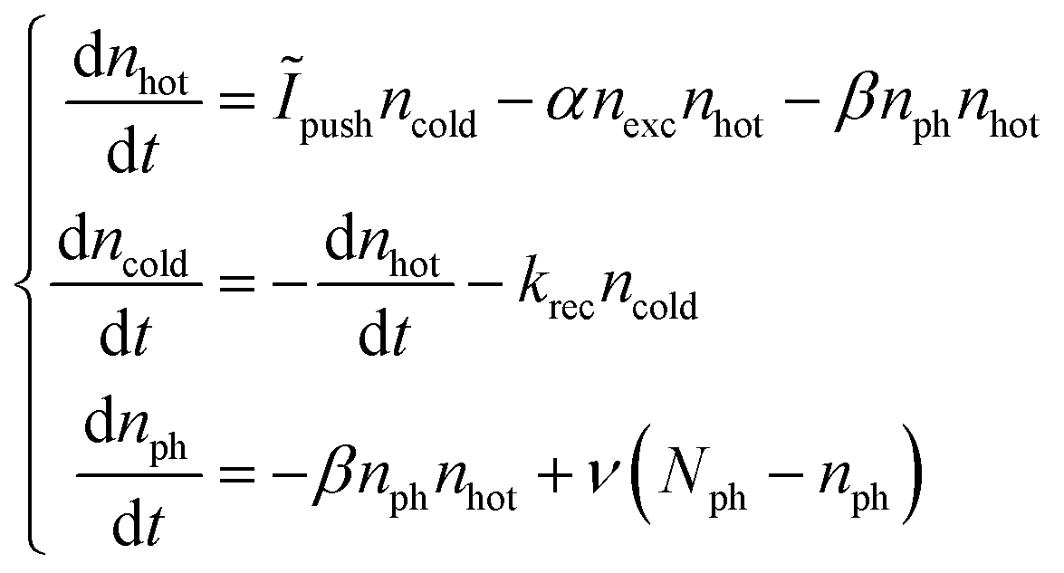 | (2) |
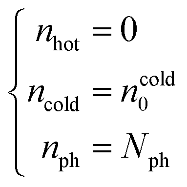 | (3) |
The hot-phonon bottleneck arises from the −βnphnhot component of the rate equation for nhot; this component is proportional to the unoccupied phonon density, which depletes during the carrier–phonon interaction. The bottleneck becomes prominent if the rate of phonon depletion is greater than or comparable to the rate of phonon scattering (the dissipation of hot phonons to the lattice), i.e. −βnhotnph ≥ ν(Nph − nph). The effect of carrier density is expressed in −αnexcnhot; an increased rate of carrier–carrier interactions is expected for a greater number of carriers. When carrier relaxation is modelled without this term, τrelax increases exponentially with respect to nhot. This is clearly not what we observe in the experimental data in Fig. 2. Fig. S2 (ESI†) shows that a similar issue arises when −αnexc is substituted for −αncold, where ncold is obtained from nexc − nhot. These findings corroborate the occurrence of strong carrier–carrier interactions when carriers are elevated to the hot state and a significant proportion of the cold carriers are depleted by the push pulse. Based on this, we are confident that we can neglect the absolute temperature of the carriers in our model. In any case, the sub-ps hot carrier lifetimes we observe are consistent with other pump–probe studies that use a Maxwell–Boltzmann temperature model to describe a Fermi–Dirac distribution of carriers.6–12
This system can be numerically solved to provide a full picture of the process, as shown in Fig. 3(a). The result is comprehensive but involves too many parameters for the analysis of carrier dynamics. Considering that the ∼50 fs push pulse is shorter than the ∼500 fs cooling times,16,19 we can assume that the intraband excitation is immediate and hence Ĩpushncold ≈ 0 after 100 fs, i.e. the time window of interest. Furthermore, the recombination lifetime is relatively slow (≫100 ps),32 and thus can be neglected (krec ≈ 0). Consequently, nexc becomes a constant (nexc = ncold0) and the rate equation for ncold becomes obsolete. The system simplifies into the form shown in eqn (4), with the initial conditions shown in eqn (5):
 | (4) |
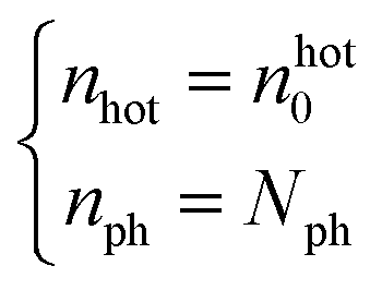 | (5) |
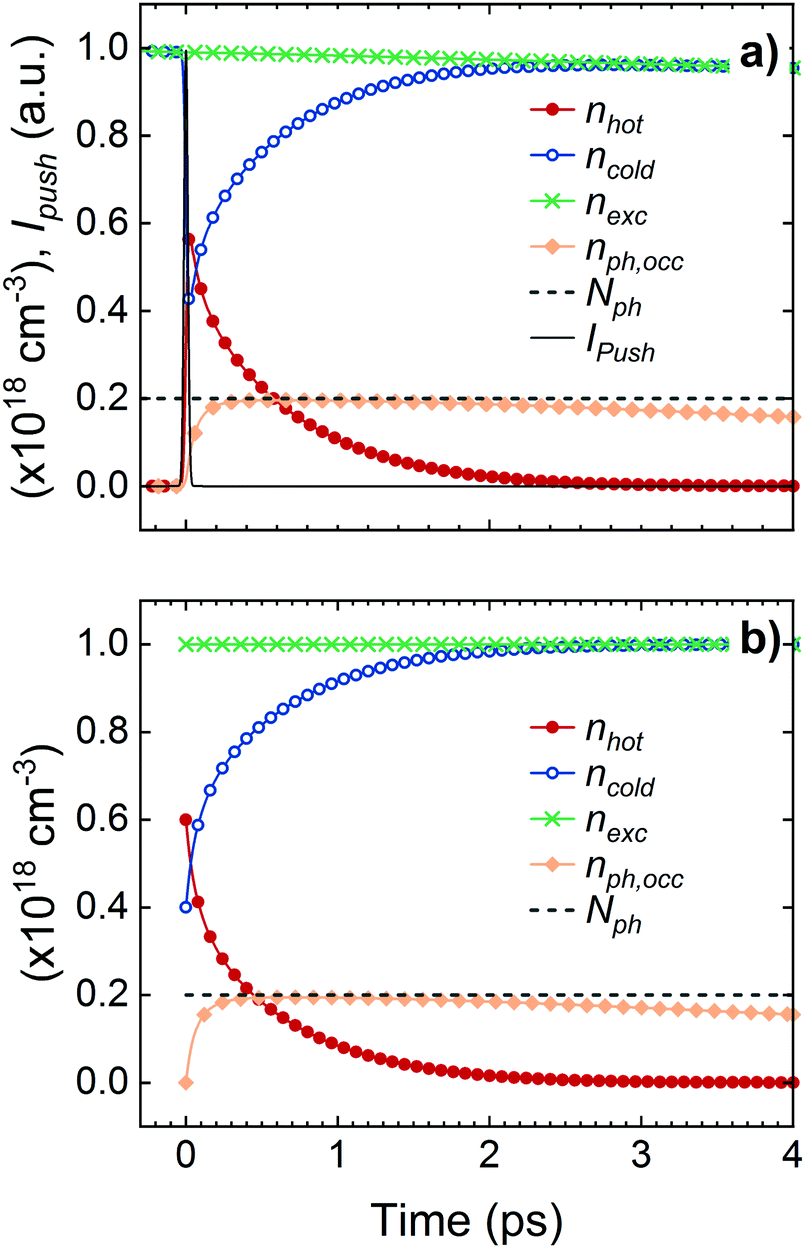 | ||
| Fig. 3 Simulated carrier and phonon population dynamics. The dynamic occupied phonon density, nph,occ = Nph − nph. (a) Results using the initial conditions from eqn (2) and (3). Constant parameters used: α = 1.4 × 10⁻¹⁸ cm3 ps−1, β = 2.7 × 10⁻¹⁷ cm3 ps−1, krec = 10−2 ps−1, ν = 10−1 ps−1. Boundary conditions used: ncold0 = 1.0 × 1018 cm−3, nhot0 = 6.0 × 1017 cm−3, Nph = 2.0 × 1017 cm−3. Pulse duration: 35 fs. (b) Results using the simplified conditions from eqn (4) and (5) and the same boundary conditions as (a). Constant parameters used: α = 1.4 × 10⁻¹⁸ cm3 ps−1, β = 2.7 × 10⁻¹⁷ cm3 ps−1, ν = 10−1 ps−1. All parameters are on the same order of magnitude as the experimentally determined values. | ||
The rate equation for nhot involves a variable (nph). This can be eliminated using the following expression from the rate equation of nhot and nph. All other parameters are constants.
 | (6) |
We can neglect the ν(Nph − nph) term based on the assumption that the phonon scattering is significantly slower than the carrier–phonon interaction. This notion is valid as long as the phonon lifetimes are not substantially shorter than the carrier-induced cooling,33–36 and is confirmed by comparing the static and dynamic phonon behaviour, shown later.
Using the initial condition shown in eqn (5):
 | (7) |
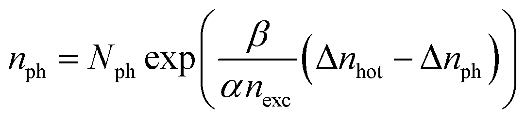 | (8) |
In order to derive the equation for further simplification, and extract a physical quantity related to polaron overlap, we assume that each hot carrier occupies a specific volume, V′, where carrier–phonon coupling can occur.15 Then we divide a unit volume (V) of the lattice into uniform cells with the volume V′. The hot carriers can occupy any of the cells, and can either overlap or not overlap with each other. The phonons are assumed to be evenly scattered across the lattice, and only one of the overlapping hot carriers can interact with the phonon modes in the cell. When (nhot0 − nhot)V carriers are coupled and dropped into the cells with the volume V′ in a lattice with Nph phonons per unit volume, then the average number of accessible phonons per unit volume (nph) can be expressed by eqn (9):
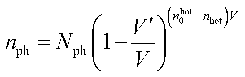 | (9) |
Given that 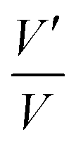 is a small number, the following approximation can be made:
| nph = Nphexp(V′nhot) | (10) |
Fig. 4(a) and (b) compare the expression of nph from the eqn (4), (5) and (10) in the time domain. We demonstrate that the use of eqn (10) is a reasonable approximation of nph in eqn (4) and (5), especially at early times <1 ps.
 | ||
| Fig. 4 Simulated hot carrier and phonon population dynamics, accounting for the dynamic occupied phonon density, nph,occ = Nph − nph, with values obtained from eqn (4) and (5), and the static occupied phonon density, nph,occ*, obtained from eqn (10). (a) and (b) show the effect when the initial hot carrier density, nhot0, is set to 6.0 × 10¹⁷ and 3.0 × 1017 cm−3, respectively. All other parameters are kept constant: α = 1.4 × 10⁻¹⁸ cm3 ps−1, β = 2.7 × 10⁻¹⁷ cm3 ps−1, ν = 10−1 ps−1, nexc = 1.0 × 1018 cm−3, V′ = 7.0 × 10⁻¹⁸ cm3. Boundary condition: Nph = 2.0 × 1017 cm−3. | ||
The rate equation for nhot can be expressed as:
 | (11) |
Eqn (11) includes the product of two arbitrary constants (βNph), allowing the elimination of a parameter. β is defined as the average spatial volume around a hot carrier where a phonon mode will interact with the carrier with ∼100% probability in 1 ps. βNph can be substituted by ρV′, where V′ is the volume of space around a hot carrier where phonons are coupled, and ρ is the number of carrier–phonon interactions per unit volume per 1 ps. Both βNph and ρV′ represent the number of carrier–phonon interactions per hot carrier per 1 ps. Hence, the rate equation can be expressed as:
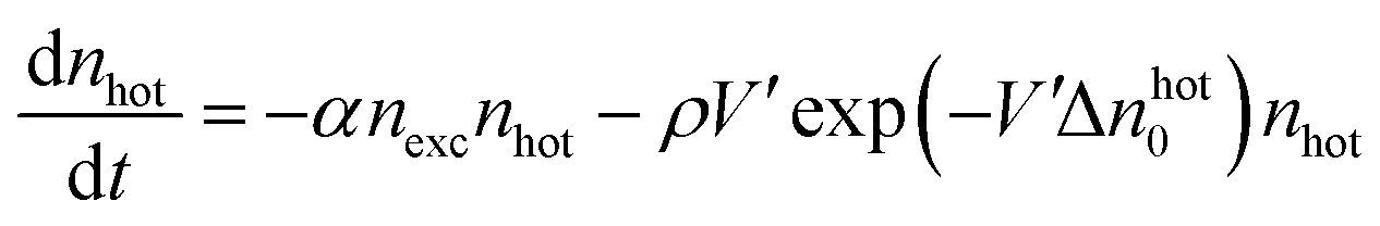 | (12) |
The hot-phonon bottleneck arises from the reduced number of available phonon modes with increasing hot carrier density, expressed as ρV′exp(−V′nhot0). The carrier–carrier interaction is contained in the −αnexcnhot component; the rate of the interaction is proportional to the carrier density. The relaxation time is calculated using the following expression:
 | (13) |
Based on this equation, we fit the experimental data from the CsPbBr3 NCs and bulk material for comparison. The fits and experimental data are shown in Fig. 2 and 5 for the respective samples. It should be emphasised that all data are globally fit with a handful of free parameters, and slight deviations are to be expected. Overall, the model qualitatively describes the whole data set, and quantitatively describes most of the data set. Table 1 contains the derived material constants.
 | ||
| Fig. 5 Plot of experimental data (points) and fits from the model (solid lines) for bulk CsPbBr3. | ||
| Material | α (10−18 cm3 ps−1) | ρ (1018 cm3 ps−1) | V’ (10−18 cm3) |
|---|---|---|---|
| CsPbBr3 NCs | 1.08 | 0.43 | 7.00 |
| Bulk CsPbBr3 | 1.95 | 0.46 | 7.58 |
Fig. 5 shows that the overall trend in cooling behaviour as a function of both the hot and cold carrier density is similar to that observed for the NC sample. Likewise, the material constants for both systems in Table 1 are almost identical. Translating the carrier–carrier interaction constant into a carrier density gives a value of ∼1018 cm−3, which is consistent with the predicted onset of a Mott transition (overlap of polarons),15 and also matches the excitation regime where Auger recombination begins to influence carrier dynamics in LHPs.16,37
The fact that we observe similar cooling dynamics and a comparable carrier–phonon interaction constant in bulk and NC CsPbBr3 tentatively implies that the additional grain boundaries in the NC sample do not strongly affect the phonon density of states, as one might expect for a nanostructured material.38 As outlined above, our cuboidal NCs are efficiently packed, resulting in voids which are substantially smaller than the NCs themselves. Taking this, and the fact that the carrier delocalisation distance in CsPbBr3 is estimated to be ∼7 nm23 (comparable to the NC edge length), we posit that a phonon originating in a given NC has a similar pool of phonons to interact with as in the bulk material, and these phonons do not need to propagate far before encountering a carrier in an adjacent NC.
Following the argument above, using the derived value of V′ we estimated the propagation distance for non-equilibrium phonons in each of the materials; in other words how far the lattice will “feel” the presence of a charge. We extract values of 12.1 and 11.9 nm for bulk CsPbBr3 and the CsPbBr3 NCs respectively. The fact that these values exceed the average NC edge implies that there is very efficient exchange of electronic and vibrational energy in LHP NC solids, which takes place on the sub-ps timescale. Given this timescale, we can use the model parameters to compare the carrier–carrier and carrier–phonon interaction distances. The values above indicate that for CsPbBr3 and its NC analogue, the typical distance at which carrier–phonon interactions start playing a role is ∼12 nm. This is slightly larger than the typical carrier–carrier interaction distance which, when deduced from α, is ∼7 nm. These absolute values are higher estimates of the actual numbers due to the anticipated underestimation of the local carrier density. However, the estimated α and V′ depend on carrier density in the same way, so the ratio between these parameters should be captured by the model correctly. Our observation that the carrier–carrier interactions are active at shorter distances than the carrier–phonon interactions is consistent with the notion of polaronic screening in LHPs.39–41
5. Conclusion
In summary, we developed a numerical model which includes “carrier–carrier” and “carrier–phonon” interaction terms to describe the role of the hot and cold carriers on the carrier relaxation kinetics of bulk and nanocrystalline CsPbBr3 films determined by “pump–push–probe” spectroscopy. The observation of slower relaxation kinetics at higher push intensity (higher hot carrier density) is explained by invoking a hot-phonon bottleneck mechanism where overlapping hot polarons compete for phonons in order to relax. This is incorporated in our model by the carrier–phonon term which describes the spatial overlap between the hot polaron states. Meanwhile, the observation of faster relaxation for higher pump intensity is attributed to the redistribution of energy from a hot carrier to adjacent cold carriers, as described by the carrier–carrier term. By fitting our model to the experimental results, we demonstrate the interplay between these contrasting effects, and propose a way to estimate the phonon density of the lattice and the rate constant for carrier–carrier and carrier–phonon interactions.Conflicts of interest
There are no conflicts to declare.Acknowledgements
The authors thank Dr Frank Krumeich for performing the electron microscopy measurements. A. A. B. is a Royal Society University Research Fellow. A. J. thanks the Royal Society for supporting the project. A. G. thanks Mr Amirlan Sekenbayev of Queen Mary University for useful discussions. This project has also received funding from the European Research Council (ERC) under the European Union's Horizon 2020 research and innovation programme (Grant Agreement No. 639750).References
- A. Kojima, K. Teshima, Y. Shirai and T. Miyasaka, J. Am. Chem. Soc., 2009, 131, 6050–6051 CrossRef CAS PubMed
.
- NREL, Best Research-Cell Efficiences Chart, https://www.nrel.gov/pv/assets/pdfs/best-research-cell-efficiencies.20190802.pdf, accessed 30 June 2020.
- W. Shockley and H. J. Queisser, J. Appl. Phys., 1961, 32, 510–519 CrossRef CAS
- R. T. Ross and A. J. Nozik, J. Appl. Phys., 1982, 53, 3813–3818 CrossRef CAS
- S. Kahmann and M. A. Loi, J. Mater. Chem. C, 2019, 7, 2471–2486 RSC
- M. B. Price, J. Butkus, T. C. Jellicoe, A. Sadhanala, A. Briane, J. E. Halpert, K. Broch, J. M. Hodgkiss, R. H. Friend and F. Deschler, Nat. Commun., 2015, 6, 8420 CrossRef CAS PubMed
- Y. Yang, D. P. Ostrowski, R. M. France, K. Zhu, J. van de Lagemaat, J. M. Luther and M. C. Beard, Nat. Photonics, 2016, 10, 53–59 CrossRef CAS
- J. Yang, X. Wen, H. Xia, R. Sheng, Q. Ma, J. Kim, P. Tapping, T. Harada, T. W. Kee, F. Huang, Y.-B. Cheng, M. Green, A. Ho-Baillie, S. Huang, S. Shrestha, R. Patterson and G. Conibeer, Nat. Commun., 2017, 8, 14120 CrossRef CAS PubMed
- P. Papagiorgis, L. Protesescu, M. V. Kovalenko, A. Othonos and G. Itskos, J. Phys. Chem. C, 2017, 121, 12434–12440 CrossRef CAS
- M. Li, S. Bhaumik, T. W. Goh, M. S. Kumar, N. Yantara, M. Grätzel, S. Mhaisalkar, N. Mathews and T. C. Sum, Nat. Commun., 2017, 8, 14350 CrossRef CAS PubMed
- J. Chen, M. E. Messing, K. Zheng and T. T. Pullerits, J. Am. Chem. Soc., 2019, 141, DOI:10.1021/jacs.8b11867
- B. T. Diroll and R. D. Schaller, Adv. Funct. Mater., 2019, 29, 1901725 CrossRef
- J. Shah, Solid-State Electron., 1978, 21, 43–50 CrossRef CAS
- R. F. Leheny, J. Shah, R. L. Fork, C. V. Shank and A. Migus, Solid State Commun., 1979, 31, 809–813 CrossRef CAS
- J. M. Frost, L. D. Whalley and A. Walsh, ACS Energy Lett., 2017, 2, 2647–2652 CrossRef CAS PubMed
- T. R. Hopper, A. Gorodetsky, J. M. Frost, C. Müller, R. Lovrincic and A. A. Bakulin, ACS Energy Lett., 2018, 3, 2199–2205 CrossRef CAS PubMed
- J. M. Richter, F. Branchi, F. Valduga de Almeida Camargo, B. Zhao, R. H. Friend, G. Cerullo and F. Deschler, Nat. Commun., 2017, 8, 376 CrossRef PubMed
- T. Ghosh, S. Aharon, L. Etgar and S. Ruhman, J. Am. Chem. Soc., 2017, 139, 18262–18270 CrossRef CAS PubMed
- T. R. Hopper, A. Gorodetsky, A. Jeong, F. Krieg, M. I. Bodnarchuk, M. Maimaris, M. Chaplain, T. J. Macdonald, X. Huang, R. Lovrincic, M. V. Kovalenko and A. A. Bakulin, Nano Lett., 2020, 20, 2271–2278 CrossRef CAS PubMed
- R. A. Kerner, L. Zhao, Z. Xiao and B. P. Rand, J. Mater. Chem. A, 2016, 4, 8308–8315 RSC
- J. Endres, D. A. Egger, M. Kulbak, R. A. Kerner, L. Zhao, S. H. Silver, G. Hodes, B. P. Rand, D. Cahen, L. Kronik and A. Kahn, J. Phys. Chem. Lett., 2016, 7, 2722–2729 CrossRef CAS PubMed
- F. Krieg, S. T. Ochsenbein, S. Yakunin, S. ten Brinck, P. Aellen, A. Süess, B. Clerc, D. Guggisberg, O. Nazarenko, Y. Shynkarenko, S. Kumar, C.-J. Shih, I. Infante and M. V. Kovalenko, ACS Energy Lett., 2018, 3, 641–646 CrossRef CAS PubMed
- L. Protesescu, S. Yakunin, M. I. Bodnarchuk, F. Krieg, R. Caputo, C. H. Hendon, R. X. Yang, A. Walsh and M. V. Kovalenko, Nano Lett., 2015, 15, 3692–3696 CrossRef CAS PubMed
- G. R. Yettapu, D. Talukdar, S. Sarkar, A. Swarnkar, A. Nag, P. Ghosh and P. Mandal, Nano Lett., 2016, 16, 4838–4848 CrossRef CAS PubMed
- P. Guyot-Sionnest, M. Shim, C. Matranga and M. Hines, Phys. Rev. B: Condens. Matter Mater. Phys., 1999, 60, R2181–R2184 CrossRef CAS
- F. T. Rabouw, R. Vaxenburg, A. A. Bakulin, R. J. A. van Dijk-Moes, H. J. Bakker, A. Rodina, E. Lifshitz, A. L. Efros, A. F. Koenderink, D. Vanmaekelbergh, A. L. Efros, A. F. Koenderink, D. Vanmaekelbergh, A. L. Efros, A. F. Koenderink and D. Vanmaekelbergh, ACS Nano, 2015, 9, 10366–10376 CrossRef CAS PubMed
- S. S. Lim, D. Giovanni, Q. Zhang, A. Solanki, N. F. Jamaludin, J. W. M. Lim, N. Mathews, S. Mhaisalkar, M. S. Pshenichnikov and T. C. Sum, Sci. Adv., 2019, 5, eaax3620 CrossRef CAS PubMed
- K. T. Munson, C. Grieco, E. R. Kennehan, R. J. Stewart and J. B. Asbury, ACS Energy Lett., 2017, 2, 651–658 CrossRef CAS
- J. Peng, Y. Chen, K. Zheng, T. Pullerits and Z. Liang, Chem. Soc. Rev., 2017, 46, 5714–5729 RSC
- W. P. D. Wong, J. Yin, B. Chaudhary, X. Y. Chin, D. Cortecchia, S.-Z. A. Lo, A. C. Grimsdale, O. F. Mohammed, G. Lanzani and C. Soci, ACS Mater. Lett., 2020, 2, 20–27 CrossRef CAS
- L. Protesescu, S. Yakunin, M. I. Bodnarchuk, F. Krieg, R. Caputo, C. H. Hendon, R. X. Yang, A. Walsh and M. V. Kovalenko, Nano Lett., 2015, 15, 3692–3696 CrossRef CAS PubMed
- N. S. Makarov, S. Guo, O. Isaienko, W. Liu, I. Robel and V. I. Klimov, Nano Lett., 2016, 16, 2349–2362 CrossRef CAS PubMed
- M. Wang and S. Lin, Adv. Funct. Mater., 2016, 26, 5297–5306 CrossRef CAS
- L. D. Whalley, J. M. Skelton, J. M. Frost and A. Walsh, Phys. Rev. B, 2016, 94, 220301 CrossRef
- A. N. Beecher, O. E. Semonin, J.
M. Skelton, J. M. Frost, M. W. Terban, H. Zhai, A. Alatas, J. S. Owen, A. Walsh and S. J. L. Billinge, ACS Energy Lett., 2016, 1, 880–887 CrossRef CAS
- B. Li, Y. Kawakita, Y. Liu, M. Wang, M. Matsuura, K. Shibata, S. Ohira-Kawamura, T. Yamada, S. Lin, K. Nakajima and S. Liu, Nat. Commun., 2017, 8, 16086 CrossRef CAS PubMed
- L. M. Herz, Annu. Rev. Phys. Chem., 2016, 67, 65–89 CrossRef CAS PubMed
- M. Ortolani, A. Mancini, A. Budweg, D. Garoli, D. Brida and F. de Angelis, Phys. Rev. B, 2019, 99, 035435 CrossRef CAS
- X.-Y. Zhu and V. Podzorov, J. Phys. Chem. Lett., 2015, 6, 4758–4761 CrossRef CAS PubMed
- H. Zhu, K. Miyata, Y. Fu, J. Wang, P. P. Joshi, D. Niesner, K. W. Williams, S. Jin and X.-Y. Y. Zhu, Science, 2016, 353, 1409–1413 CrossRef CAS PubMed
- K. Miyata, D. Meggiolaro, M. T. Trinh, P. P. Joshi, E. Mosconi, S. C. Jones, F. De Angelis and X.-Y. Zhu, Sci. Adv., 2017, 3, e1701217 CrossRef PubMed
Footnotes |
| † Electronic supplementary information (ESI) available. See DOI: 10.1039/d0cp01599g |
| ‡ These authors contributed equally to the manuscript. |
| This journal is © the Owner Societies 2020 |