 Open Access Article
Creative Commons Attribution 3.0 Unported Licence
Electrochemical Overhauser dynamic nuclear polarization
Mika
Tamski
 a,
Jonas
Milani
*a,
Christophe
Roussel
ab and
Jean-Philippe
Ansermet
a
aInstitut de physique, Ecole Polytechnique Fédérale de Lausanne (EPFL), CH-1015 Lausanne, Switzerland. E-mail: jonas.milani@epfl.ch
bInstitut des Sciences et Ingénierie Chimiques, Ecole Polytechnique Fédérale de Lausanne (EPFL), CH-1015 Lausanne, Switzerland
First published on 21st July 2020
Abstract
Nuclear Magnetic Resonance (NMR) spectroscopy suffers from low sensitivity due to the low nuclear spin polarization obtained within practically achievable external magnetic fields. Dynamic Nuclear Polarization (DNP) refers to techniques that increase the NMR signal intensity by transferring spin polarization from electrons to the nuclei. Until now, a common method of introducing unpaired electrons to a sample has been to add to it a radical such as TEMPOL or trityl. The alternative we address here is to use electrochemical oxidation and/or reduction of a redox mediator to generate radical species that can be used for DNP. Surprisingly, the potential of electrochemically-generated radicals as a source of hyperpolarization for DNP has not been investigated so far. In this communication, we show the proof of principle of performing an in situ DNP experiment at a low magnetic field in a solution phase, with electrochemically generated methyl viologen cation radicals. Electrochemistry as a source of radicals can offer exciting prospects for DNP. The electrode may be one that generates radicals with a high spin polarization. The concentration of radicals in the sample can be adjusted by changing the duration and magnitude of the applied electrode potential. Removal of the radical from the sample after spin polarization transfer is also possible, thereby increasing the lifetime of the nuclear hyperpolarization.
Introduction
Dynamic Nuclear Polarisation (DNP) designates an array of techniques that seek to enhance NMR signals by transferring electron spin polarization to nuclei.1–3 Overhauser identified a possible mechanism that he considered applicable for electron and nuclear spins in metals.4 His prediction was verified,5,6 and extended to liquids with radicals in solution.7 The Overhauser effect (OE) can also be obtained in liquids when working with two dipolar-coupled nuclei (NOE) that have very different gyromagnetic ratios.8 After the demonstration of dissolution DNP in 2003,9 DNP regained interest and was adapted to the high fields used in modern spectrometers.10,11 At high fields, the Overhauser effect requires high microwave powers to achieve saturation,12 causing the sample solutions to overheat unless great care is taken to avoid this.13,14 It has been recently demonstrated nonetheless that a very large enhancement can be obtained at high fields.15 The Overhauser effect is not only a means to enhance signal, but has also been used to study hydration shells for example.16–19 In this paper, we open up a new application of the Overhauser effect using radicals in solutions that are generated electrochemically from an electroactive redox mediator. We demonstrate enhancements greater than 30-fold in situ, i.e. in the NMR probe, and 50-fold ex situ at low fields (0.3 T).Electrochemical reactions change the oxidation state of a redox mediator at an electrode either by reduction or by oxidation. This change in the oxidation state can generate paramagnetic species, which can be studied using Electron Paramagnetic Resonance (EPR) spectroscopy at low fields,20–23 or more recently, at high fields.24 Surface EPR is possible on high surface area materials such as catalysts.25 However, after the electrochemical oxidation or reduction, the chemical reactions that may follow could quench the radical intermediate before a satisfactory EPR spectrum can be obtained.26
Liquid state NMR can also be used to assess the time evolution of electroactive species in solution.27–32 The analysis of the electrolyte during or after an electrochemical process has been demonstrated.33 NMR can also monitor a battery under operation, provided it is built into a stripline resonator.34,35 NMR can also probe molecules adsorbed on an electrode surface;36,37 in particular, it can characterize the partial charge transfer between the electrode and the chemisorbed species.38,39 The well-known sensitivity issue of NMR renders its application in surface studies tedious. A minimum of 1017 nuclei is required to begin to envisage surface NMR, whereas a typical surface atom density is around 1015 atoms per cm2. Thus, NMR of electrode surfaces calls for either a large surface area electrode (>100 cm2), where accurate electrochemical potential control may not be possible, or signal enhancement by DNP.40
Considering the importance of being able to conduct NMR analysis of electrolytes in confined geometries, and possibly of species chemisorbed on electrodes, we have explored the extent to which electrochemistry (EC) could serve as a source of radical species for OE experiments (EC-OE). In this communication, we show a proof of principle for Overhauser-enhanced proton NMR, obtained using methyl viologen radicals MV+˙, electrochemically generated in situ from methyl viologen dication MV2+ (1,1′-dimethyl-4,4′-bipyridinium dichloride).
Electrochemical Overhauser effect DNP (EC-OE-DNP)
The Overhauser effect for an ensemble of pairs of ½-spins can be described by considering the evolution of the populations at the four energy levels. For an intermolecular Overhauser effect involving radicals as a solute and nuclei in solution, we refer to the model proposed by Armstrong based on the work of Hausser. In the liquid state, in the case of full or partial saturation of the EPR transition, the polarization enhancement ε is given by:7,41 | (1) |
 | (2) |
 | (3) |
 | (4) |
We cannot consider our system as homogenous because the radicals are generated locally at the electrode surface and subsequently distributed in the whole solution by mass transport. The mass transport is expressed by the Nernst-Planck equation, which describes the diffusion flux density J which results from diffusion, electrostatic migration and convection,
 | (5) |
Experimental
EC-OE-DNP sample
For the electrochemical characterization, a 1 mM solution of MV2+ was prepared in ACN with 200 mM of TBAP as the supporting electrolyte. For the EPR characterisation, an aliquot of this sample was electrolysed into a ca. 100 μM concentration of MV+˙ in a two compartment u-cell at a Pt electrode.43 For the electrochemical Overhauser experiments, the sample solutions contained 50 mM of MV2+ and 50 mM of TBAHP dissolved into a 20![[thin space (1/6-em)]](https://www.rsc.org/images/entities/char_2009.gif) :
:![[thin space (1/6-em)]](https://www.rsc.org/images/entities/char_2009.gif) 80 MeOH
80 MeOH![[thin space (1/6-em)]](https://www.rsc.org/images/entities/char_2009.gif) :
:![[thin space (1/6-em)]](https://www.rsc.org/images/entities/char_2009.gif) ACN (w/w) mixture, in which the solubility of MV2+ is high. All of the samples were prepared and stored in a glove box with dry nitrogen atmosphere, and taken out only in sealed test tubes for measurements.
ACN (w/w) mixture, in which the solubility of MV2+ is high. All of the samples were prepared and stored in a glove box with dry nitrogen atmosphere, and taken out only in sealed test tubes for measurements.
Electrochemistry setup
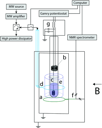
Fig. 1 displays a schematic representation of the experimental setup. The electrochemical cell was assembled into a 4 mm inner-diameter NMR tube. The working electrode (WE) was a 250 μm diameter coiled silver wire with a ca. 0.5 cm2 surface area. A Pt wire tip was used as a pseudo reference electrode (RE, not shown) and a Pt coil as the counter electrode (CE). A cotton wool plug was placed between the WE and the CE to prevent the mass transport of methyl viologen radicals (MV+˙), thus confining the electrochemically generated radical ions to the sensitive part of the NMR measurement, i.e. in the volume occupied by the WE. The electrode potential was managed with a potentiostat (Gamry Interface 1010 E). The radical generation for the EC-OE-DNP experiments was carried out via chronopotentiometry, applying a stable current for a required period of time to generate the desired radical concentration. The potential of the WE in these experiments was typically between −0.2 and −0.3 V. It is very likely that the setup presented here can be improved by integrating the electrolysis cell with the EPR resonator by commercial solution,44 or with a thin capillary setup.45NMR-DNP setup
The electrochemical Overhauser (EC-OE)-DNP experiment was conducted within a Varian electromagnet in a magnetic field B of 0.33 T. The saturation of the EPR line is done with a setup composed of a microwave (MW) source PHILIPS PM 7022X, a 200 Watt traveling wave tube amplifier, and a high frequency circulator that prevents damage by dissipating the power in a high-power resistance. The high power MW is transmitted into the sample through a coax cable and a coupling loop (d in Fig. 1), thus providing continuous microwave irradiation at the EPR resonance frequency of the MV+˙ (9.3 GHz), to a sapphire resonator (e in Fig. 1). An NMR coil was placed in the vicinity of the WE for a simultaneous 14 MHz excitation/detection. The NMR signal is managed with a home-made setup composed of a pulse generator PulseBlaster Spincore, a PTS 620 frequency synthesizer, a TOMCO RF Pulse Amplifier, a digitizer Gage Applied RazorMax, and a home-made spectrometer. The tuning and matching (T&M) trimmer capacitors (NMTIM120CEK, Municom) were located out of the sample space. In the future the NMR-DNP setup could be improved by integrating the NMR coil into the dielectric resonator, as demonstrated before.46–49The sample space (EPR resonator and NMR coil) was isolated with a brass cavity. The probe was inserted into an aluminium box that contained the T&M capacitors.
MV+˙ radicals were produced in situ in controlled quantities which were used to transfer the polarisation from the unpaired electrons to the ACN protons. A computer equipped with a Labview software pilots the NMR spectrometer, Gamry potentiostat and MW switch.
EPR spectroscopy
The EPR spectrum of MV+˙ was measured with a Magnettech MiniScope MS 400 benchtop EPR spectrometer inside a ca. 1 mm inner diameter borosilicate tube.NMR pulse sequence
The pulse sequence described in Fig. 2 was used to measure the NMR signals. The NMR transition was first completely saturated by applying a hundred 90° pulses every 5 ms. Then, the MW source irradiated the sample for 1 s and the NMR signal detection was done with a 90° pulse. The 1 s irradiation time was a compromise between the hyperpolarization process and the heating of the sample during the microwave irradiation. The optimisation of the electrolysis cell geometry and the NMR-DNP setup, as discussed above, could alleviate the heating issues in the future. The time delay between two DNP experiments was long enough to allow for a complete cool-off of the electrochemical cell.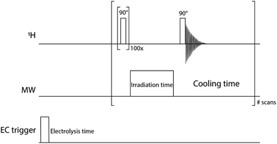 | ||
| Fig. 2 Pulse sequence of the 1H channel (14 MHz), MW channel (9.3 GHz) and DC trigger to initiate the electrochemical sequence. All the spectra in this paper were performed with small modifications of this pulse sequence. In the experiment with MW off, the pulse in the MW channel was set to zero power. The one-shot experiments were done without the EC trigger line. NMR T1 measurements were done by varying the “irradiation time” with no applied MW power. Multistep EC experiments (Fig. 5) use the entire pulse sequence. | ||
Results and discussion
According to eqn (1) and (3), the OE in liquid is maximized at a high radical concentration,41 so a system capable of creating radicals at a relatively high concentration is desired. Methylviologen dication MV2+ is a good candidate in this regard.50
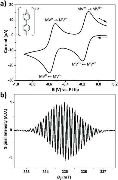
Fig. 3a shows a cyclic voltammogram of a 1 mM solution of MV2+ at a gold electrode in acetonitrile with 200 mM of TBAP as the supporting electrolyte against a Pt pseudo RE. During the forward scan, the two visible redox processes are the reduction of MV2+ into MV+˙ at around −0.16 V, and the consecutive reduction of MV+˙ into MV0 at around −0.56 V. Both processes are electrochemically reversible. The corresponding processes are depicted in Fig. 3a and the structure of the MV2+ is shown in the inset. MV+˙ can also be generated by stepping the electrode potential beyond −0.56 V to produce MV0 which then comproportionates in the vicinity of the electrode surface according to the relationship: MV0 + MV2+ ![[left over right harpoons]](https://www.rsc.org/images/entities/char_21cb.gif) 2MV+˙ with an equilibrium constant of 1 × 10⁷ in ACN.51,52
2MV+˙ with an equilibrium constant of 1 × 10⁷ in ACN.51,52
Fig. 3b shows the X-band EPR spectrum of MV+˙ recorded at a radical concentration of about 100 μM in acetonitrile with 200 mM of TBAP as the supporting electrolyte. The spectrum shows a hyperfine splitting of ca. 0.137 mT, typical for the ring protons of MV+˙.50 In acetonitrile, the larger line width masks most of the hyperfine couplings visible in aqueous solution.22,53
The electrochemical electrodes (WE, RE and CE) which are located very close to the resonator have a significant effect on the resonance of the EPR cavity, causing its resonance to be very broad. As a consequence, we needed a high-power source for MW irradiation. Our setup provided 3.2 W to the sample.
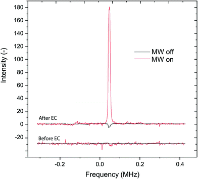
Fig. 4 presents the results before and after electro-generating the radicals. Averages of 20 scans were used for MW-on and 500 scans for MW-off measurements. After the radical production, the short T1 of the protons made possible the detection of the proton signal despite the short delay time between each scan, whereas T10 was too long to detect the NMR within this short delay time. The delay time was kept identical in all experiments. The EC-OE-DNP signal of the sample protons is enhanced by a factor of 31.
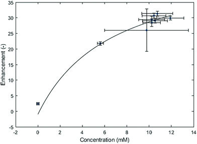
Fig. 5 presents the DNP enhancement in a stepwise increase of electrochemically generated radicals. The electrochemical step was done in situ with the setup described in the experimental section. At each step, a steady current of −1 mA was applied to the working electrode for 67 seconds, and the corresponding voltage fluctuated slowly between −0.2 and −0.3 V. The system reached roughly a maximum after the 4th EC step, leading to about 10.4 mM concentration of MV+˙ and an enhancement of 31.
The method used in this paper to determine the radical concentration is based on the 1H T1 measurements. In the liquid phase, the longitudinal relaxation time is sensitive to the concentration of the radical species. According to the model of Borah et al.,54 the concentration of MV+˙ can be determined. The T1 were measured by saturation recovery which requires quite a long acquisition time, here about 40 minutes. We recall that the setup was optimized for MW power and the NMR detection was far from optimal.
Carrying out T1 measurements needs a long time and is the likely reason for the observation of a concentration saturation. Over time, the MV+˙ diffuses through the cotton wool of the electrolysis cell (see Experimental part), thus affecting its detected concentration. This phenomenon is even more important for high concentrations of MV+˙. This is probably the source of the scatter in the data which were accumulated over long times because of the T1 measurements which were needed to get the local estimate of the concentration. This mass transport issue is further confirmed when working with solutions prepared ex situ, where a large concentration of radicals is homogeneously obtained throughout the studied sample (Fig. 6a). Extrapolation from the fitted curve in Fig. 5 yielded an enhancement of 60 at a concentration of 50 mM of radicals, which is consistent with the calibration curve obtained with the solutions prepared ex situ (Fig. 6a).
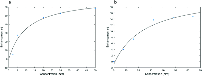 | ||
| Fig. 6 Enhancement of the 1H signal (14 MHz) after 1 s of MW irradiation in solutions that were prepared ex situ with different concentrations of either MV+˙ (a) or TEMPO (b). | ||
Fig. 6b presents the OE-DNP enhancement obtained with our setup (Fig. 1) when using tetramethylpiperidinyloxyl (TEMPO) radicals at different concentrations in acetonitrile. Surprisingly, the MV+˙ gave a significantly higher OE-DNP enhancement than TEMPO under exactly the same conditions. The biggest enhancement factor obtained with MV+˙ at 50 mM was 57, whereas the observed enhancement factor with TEMPO at 64 mM was found to be 15. This difference in enhancement under identical experimental conditions should reflect the difference of coupling factors or saturation factor pertaining to these two radicals.
Conclusion
In conclusion, we have demonstrated the possibility to produce an Overhauser-enhanced proton signal by means of electro-generated radicals. One of the main advantages of this process is the ability to quench the radicals without heating55 or adding a chemical56 after the polarisation transfer in order to remove the paramagnetic centres. Using reversible redox couples, one can invert the electrochemical process to provide a diamagnetic species from the radical, either by oxidation (MV+˙ → MV2+) or by reduction (MV+˙ → MV0). Based on these encouraging results, other redox mediators should be tested, and the setup optimized in order to get better thermal control and larger enhancements.Further tests are needed to evaluate the benefits of this method. For example, it may be of use in high-resolution NMR, as the radicals could be quenched right after hyperpolarizing the nuclei in order to avoid paramagnetic line broadening. The working electrode would have to be optimized so that it does not introduce any field inhomogeneity. The application of the Chirality-Induced Spin Selectivity (CISS) effect43 should also be explored as a method for hyperpolarising the electron spins, as it may greatly simplify the method to achieve OE at high fields.
Conflicts of interest
There are no conflicts to declare.References
- A. Abragam, The Principles of Nuclear Magnetism, Reprinted, Oxford: Clarendon Press, Oxford, 1994, vol. 32 Search PubMed.
- W. T. Wenckebach, Essentials of Dynamic Nuclear Polarization, Spindrift Publications, Burgh-Haamstede, 2016 Search PubMed.
- C. D. Jeffries, Dynamic Nuclear Orientation, Interscience Publishers, New York, 1963 Search PubMed.
- A. W. Overhauser, Polarization of Nuclei in Metals, Phys. Rev., 1953, 92(2), 411–415, DOI:10.1103/PhysRev.92.411.
- C. P. Slichter, The Discovery and Demonstration of Dynamic Nuclear Polarization—a Personal and Historical Account, Phys. Chem. Chem. Phys., 2010, 12(22), 5741–5751, 10.1039/C003286G.
- T. R. Carver and C. P. Slichter, Experimental Verification of the Overhauser Nuclear Polarization Effect, Phys. Rev., 1956, 102(4), 975–980, DOI:10.1103/PhysRev.102.975.
- K. H. Hausser and D. Stehlik, Dynamic Nuclear Polarization in Liquids, in Advances in Magnetic Resonance, ed. J. S. Waugh, Academic Press, 1968, vol. 3, 79–139, DOI:10.1016/B978-1-4832-3116-7.50010-2.
- R. R. Ernst, G. Bodenhausen and A. Wokaun, Principles of Nuclear Magnetic Resonance in One and Two Dimensions, Clarendon Press, Oxford University Press, Oxford, Oxfordshire, New York, 1987 Search PubMed.
- J. H. Ardenkjær-Larsen, B. Fridlund, A. Gram, G. Hansson, L. Hansson, M. H. Lerche, R. Servin, M. Thaning and K. Golman, Increase in Signal-to-Noise Ratio of >10
![[thin space (1/6-em)]](https://www.rsc.org/images/entities/char_2009.gif) 000 Times in Liquid-State NMR, Proc. Natl. Acad. Sci. U. S. A., 2003, 100(18), 10158–10163 CrossRef PubMed.
000 Times in Liquid-State NMR, Proc. Natl. Acad. Sci. U. S. A., 2003, 100(18), 10158–10163 CrossRef PubMed. - V. S. Bajaj, C. T. Farrar, M. K. Hornstein, I. Mastovsky, J. Vieregg, J. Bryant, B. Eléna, K. E. Kreischer, R. J. Temkin and R. G. Griffin, Dynamic Nuclear Polarization at 9T Using a Novel 250 GHz Gyrotron Microwave Source, J. Magn. Reson., 2003, 160(2), 85–90, DOI:10.1016/S1090-7807(02)00192-1.
- J. H. Ardenkjaer-Larsen, On the Present and Future of Dissolution-DNP, J. Magn. Reson., 2016, 264, 3–12, DOI:10.1016/j.jmr.2016.01.015.
- N. M. Loening, M. Rosay, V. Weis and R. G. Griffin, Solution-State Dynamic Nuclear Polarization at High Magnetic Field, J. Am. Chem. Soc., 2002, 124(30), 8808–8809, DOI:10.1021/ja026660g.
- D. Yoon, A. I. Dimitriadis, M. Soundararajan, C. Caspers, J. Genoud, S. Alberti, E. de Rijk and J.-P. Ansermet, High-Field Liquid-State Dynamic Nuclear Polarization in Microliter Samples, Anal. Chem., 2018, 90(9), 5620–5626, DOI:10.1021/acs.analchem.7b04700.
- V. Denysenkov, M. J. Prandolini, M. Gafurov, D. Sezer, B. Endeward and T. F. Prisner, Liquid State DNP Using a 260 GHz High Power Gyrotron, Phys. Chem. Chem. Phys., 2010, 12(22), 5786–5790, 10.1039/C003697H.
- G. Liu, M. Levien, N. Karschin, G. Parigi, C. Luchinat and M. Bennati, One-Thousand-Fold Enhancement of High Field Liquid Nuclear Magnetic Resonance Signals at Room Temperature, Nat. Chem., 2017, 9(7), 676–680, DOI:10.1038/nchem.2723.
- E. R. McCarney, B. D. Armstrong, R. Kausik and S. Han, Dynamic Nuclear Polarization Enhanced Nuclear Magnetic Resonance and Electron Spin Resonance Studies of Hydration and Local Water Dynamics in Micelle and Vesicle Assemblies, Langmuir, 2008, 24(18), 10062–10072, DOI:10.1021/la800334k.
- C.-Y. Cheng, J. Varkey, M. R. Ambroso, R. Langen and S. Han, Hydration Dynamics as an Intrinsic Ruler for Refining Protein Structure at Lipid Membrane Interfaces, Proc. Natl. Acad. Sci. U. S. A., 2013, 110(42), 16838–16843 CrossRef CAS PubMed.
- B. D. Armstrong, J. Choi, C. López, D. A. Wesener, W. Hubbell, S. Cavagnero and S. Han, Site-Specific Hydration Dynamics in the Nonpolar Core of a Molten Globule by Dynamic Nuclear Polarization of Water, J. Am. Chem. Soc., 2011, 133(15), 5987–5995, DOI:10.1021/ja111515s.
- J. M. Franck and S. Han, Overhauser Dynamic Nuclear Polarization for the Study of Hydration Dynamics, Explained, in Methods in Enzymology, Academic Press Inc., 2019, vol. 615, pp. 131–175 Search PubMed.
- J. D. Wadhawan and R. G. Compton, EPR Spectroscopy in Electrochemistry, Encycl. Electrochem., 2007 DOI:10.1002/9783527610426.bard020302.
- A. M. Waller and R. G. Compton, In Situ Electrochemical ESR. Comprehensive Chemical Kinetics, ed. R. G. Compton, Elsevier, 1989, pp. 297–352 Search PubMed.
- M. A. Tamski, J. V. Macpherson, P. R. Unwin and M. E. Newton, Electrochemical Electron Paramagnetic Resonance Utilizing Loop Gap Resonators and Micro-Electrochemical Cells, Phys. Chem. Chem. Phys., 2015, 17(36), 23438–23447, 10.1039/C5CP04259C.
- M. A. Tamski, M. W. Dale, B. G. Breeze, J. V. Macpherson, P. R. Unwin and M. E. Newton, Quantitative Measurements in Electrochemical Electron Paramagnetic Resonance, Electrochim. Acta, 2016, 213, 802–810, DOI:10.1016/j.electacta.2016.07.114.
- P. R. Murray, D. Collison, S. Daff, N. Austin, R. Edge, B. W. Flynn, L. Jack, F. Leroux, E. J. L. McInnes and A. F. Murray, et al., An in Situ Electrochemical Cell for Q- and W-Band EPR Spectroscopy, J. Magn. Reson., 2011, 213(1), 206–209, DOI:10.1016/j.jmr.2011.09.041.
- D. M. Murphy and M. Chiesa, EPR of Paramagnetic Centres on Solid Surfaces, in Electron Paramagnetic Resonance, The Royal Society of Chemistry, 2008, vol. 21, pp. 105–130 10.1039/B709153M.
- R. D. Allendoerfer, G. A. Martinchek and S. Bruckenstein, Simultaneous Electrochemical-Electron Spin Resonance Measurements with a Coaxial Microwave Cavity, Anal. Chem., 1975, 47(6), 890–894, DOI:10.1021/ac60356a023.
- S. Klod and L. Dunsch, A Combination of in situ ESR and in situ NMR Spectroelectrochemistry for Mechanistic Studies of Electrode Reactions: The Case of p-Benzoquinone, Magn. Reson. Chem., 2011, 49(11), 725–729, DOI:10.1002/mrc.2819.
- L. M. S. Nunes, T. B. Moraes, L. L. Barbosa, L. H. Mazo and L. A. Colnago, Monitoring Electrochemical Reactions in situ Using Steady-State Free Precession 13C NMR Spectroscopy, Anal. Chim. Acta, 2014, 850, 1–5, DOI:10.1016/j.aca.2014.05.022.
- P. F. da Silva, B. F. Gomes, C. M. S. Lobo, L. H. K. Q. Júnior, E. Danieli, M. Carmo, B. Blümich and L. A. Colnago, Electrochemical NMR Spectroscopy: Electrode Construction and Magnetic Sample Stirring, Microchem. J., 2019, 146, 658–663, DOI:10.1016/j.microc.2019.01.010.
- U. Bussy and M. Boujtita, Review of Advances in Coupling Electrochemistry and Liquid State NMR, Talanta, 2015, 136, 155–160, DOI:10.1016/j.talanta.2014.08.033.
- D. W. Mincey, M. J. Popovich, P. J. Faustino, M. M. Hurst and J. A. Caruso, Monitoring of Electrochemical Reactions by Nuclear Magnetic Resonance Spectrometry, Anal. Chem., 1990, 62(11), 1197–1200, DOI:10.1021/ac00210a020.
- P. D. Prenzler, R. Bramley, S. R. Downing and G. A. Heath, High-Field NMR Spectroelectrochemistry of Spinning Solutions: Simultaneous in situ Detection of Electrogenerated Species in a Standard Probe under Potentiostatic Control1A Preliminary Account of This Work Was Presented at AISAS 99, Melbourne, Australia, J. Electrochem. Commun., 2000, 2(7), 516–521, DOI:10.1016/S1388-2481(00)00042-4.
- C. W. Li, J. Ciston and M. W. Kanan, Electroreduction of Carbon Monoxide to Liquid Fuel on Oxide-Derived Nanocrystalline Copper, Nature, 2014, 508(7497), 504–507, DOI:10.1038/nature13249.
- N. Yamakawa, M. Jiang, B. Key and C. P. Grey, Identifying the Local Structures Formed during Lithiation of the Conversion Material, Iron Fluoride, in a Li Ion Battery: A Solid-State NMR, X-Ray Diffraction, and Pair Distribution Function Analysis Study, J. Am. Chem. Soc., 2009, 131(30), 10525–10536, DOI:10.1021/ja902639w.
- E. G. Sorte, N. A. Banek, M. J. Wagner, T. M. Alam and Y. J. Tong, In Situ Stripline Electrochemical NMR for Batteries, ChemElectroChem, 2018, 5(17), 2336–2340, DOI:10.1002/celc.201800434.
- J. Wu, J. B. Day, K. Franaszczuk, B. Montez, E. Oldfield, A. Wieckowski, P.-A. Vuissoz and J.-P. Ansermet, Recent Progress in Surface NMR-Electrochemistry, J. Chem. Soc., Faraday Trans., 1997, 93(6), 1017–1026, 10.1039/A603611B.
- P. J. Slezak and A. Wieckowski, Interfacing Surface Electrochemistry with Solid-State NMR. Characterization of Surface Co on Polycrystalline Platinum, J. Magn. Reson., Ser. A, 1993, 166–172, DOI:10.1006/jmra.1993.1086.
- K. Tedsree, C. W. A. Chan, S. Jones, Q. Cuan, W.-K. Li, X.-Q. Gong and S. C. E. Tsang, 13C NMR Guides Rational Design of Nanocatalysts via Chemisorption Evaluation in Liquid Phase, Science, 2011, 332(6026), 224–228, DOI:10.1126/science.1202364.
- J. B. Day, P.-A. Vuissoz, E. Oldfield, A. Wieckowski and J.-P. Ansermet, Nuclear Magnetic Resonance Spectroscopic Study of the Electrochemical Oxidation Product of Methanol on Platinum Black, J. Am. Chem. Soc., 1996, 118(51), 13046–13050, DOI:10.1021/ja962490u.
- B. J. Walder, C. Berk, W.-C. Liao, A. J. Rossini, M. Schwarzwälder, U. Pradere, J. Hall, A. Lesage, C. Copéret and L. Emsley, One- and Two-Dimensional High-Resolution NMR from Flat Surfaces, ACS Cent. Sci., 2019, 5(3), 515–523, DOI:10.1021/acscentsci.8b00916.
- B. D. Armstrong and S. Han, A New Model for Overhauser Enhanced Nuclear Magnetic Resonance Using Nitroxide Radicals, J. Chem. Phys., 2007, 127(10), 104508, DOI:10.1063/1.2770465.
- I. Nicholson, D. J. Lurie and F. J. L. Robb, The Application of Proton-Electron Double-Resonance Imaging Techniques to Proton Mobility Studies, J. Magn. Reson., Ser. B, 1994, 104(3), 250–255, DOI:10.1006/jmrb.1994.1082.
- F. Blumenschein, M. Tamski, C. Roussel, E. Z. B. Smolinsky, F. Tassinari, R. Naaman and J.-P. Ansermet, Spin-Dependent Charge Transfer at Chiral Electrodes Probed by Magnetic Resonance, Phys. Chem. Chem. Phys., 2020, 22(3), 997–1002, 10.1039/C9CP04681J.
- M. Toybenshlak and R. Carmieli, A New and Robust Method for In Situ EPR Electrochemistry, Isr. J. Chem., 2019, 59(11–12), 1020–1026, DOI:10.1002/ijch.201900074.
- M. A. Morsy and A.-N. M. Kawde, Electron Paramagnetic Resonance Monitoring for On-Demand Electrochemically-Generated Radicals, Electrochim. Acta, 2015, 160, 22–27, DOI:10.1016/j.electacta.2015.02.014.
- G. Annino, J. A. Villanueva-Garibay, P. J. M. van Bentum, A. A. K. Klaassen and A. P. M. Kentgens, A High-Conversion-Factor, Double-Resonance Structure for High-Field Dynamic Nuclear Polarization, Appl. Magn. Reson., 2009, 37(1), 851, DOI:10.1007/s00723-009-0091-6.
- A. Doll, E. Bordignon, B. Joseph, R. Tschaggelar and G. Jeschke, Liquid State DNP for Water Accessibility Measurements on Spin-Labeled Membrane Proteins at Physiological Temperatures, J. Magn. Reson., 2012, 222, 34–43, DOI:10.1016/j.jmr.2012.06.003.
- B. Armstrong, M. Lingwood, E. McCarney, E. Brown, P. Blümler and S. Han, Portable X-Band System for Solution State Dynamic Nuclear Polarization, J. Magn. Reson., 2008, 191, 273–281, DOI:10.1016/j.jmr.2008.01.004.
- O. Neudert, C. Mattea and S. Stapf, A Compact X-Band Resonator for DNP-Enhanced Fast-Field-Cycling NMR, J. Magn. Reson., 2016, 271, 7–14, DOI:10.1016/j.jmr.2016.08.002.
- W. R. Dunham, J. A. Fee, L. J. Harding and H. J. Grande, Application of Fast Fourier Transforms to EPR Spectra of Free Radicals in Solution, J. Magn. Reson., 1980, 40(2), 351–359, DOI:10.1016/0022-2364(80)90258-9.
- P. M. S. Monk, R. D. Fairweather, M. D. Ingram and J. A. Duffy, Evidence for the Product of the Viologen Comproportionation Reaction Being a Spin-Paired Radical Cation Dimer, J. Chem. Soc., Perkin Trans. 2, 1992, 2039–2041, 10.1039/P29920002039.
- C. L. Bird and A. T. Kuhn, Electrochemistry of the Viologens, Chem. Soc. Rev., 1981, 10(1), 49, 10.1039/CS9811000049.
- J. G. Gaudiello, P. K. Ghosh and A. J. Bard, Polymer Films on Electrodes. 17. The Application of Simultaneous Electrochemical and Electron Spin Resonance Techniques for the Study of Two Viologen-Based Chemically Modified Electrodes, J. Am. Chem. Soc., 1985, 107(11), 3027–3032, DOI:10.1021/ja00297a006.
- B. Borah and R. G. Bryant, NMR Relaxation Dispersion in an Aqueous Nitroxide System, J. Chem. Phys., 1981, 75(7), 3297–3300, DOI:10.1063/1.442480.
- A. Capozzi, T. Cheng, G. Boero, C. Roussel and A. Comment, Thermal Annihilation of Photo-Induced Radicals Following Dynamic Nuclear Polarization to Produce Transportable Frozen Hyperpolarized 13C-Substrates, Nat. Commun., 2017, 8(1), 15757, DOI:10.1038/ncomms15757.
- P. Miéville, P. Ahuja, R. Sarkar, S. Jannin, P. R. Vasos, S. Gerber-Lemaire, M. Mishkovsky, A. Comment, R. Gruetter and O. Ouari, et al., Scavenging Free Radicals To Preserve Enhancement and Extend Relaxation Times in NMR Using Dynamic Nuclear Polarization, Angew. Chem., Int. Ed., 2010, 49(35), 6182–6185, DOI:10.1002/anie.201000934.
| This journal is © the Owner Societies 2020 |

