 Open Access Article
Interference of a resonance state with itself: a route to control its dynamical behaviour
A.
García-Vela

Instituto de Física Fundamental, Consejo Superior de Investigaciones Científicas, Serrano 123, 28006 Madrid, Spain. E-mail: garciavela@iff.csic.es
First published on 5th June 2020
Abstract
It is demonstrated both numerically and mathematically that the dynamical behavior of an isolated resonance state, which comprises the resonance decay lifetime and the asymptotic fragment state distribution produced upon resonance decay, can be extensively controlled by means of quantum interference induced by a laser field in the weak-field regime. The control scheme applied is designed to induce interference between amplitudes excited at two different energies of the resonance line shape, namely the resonance energy and an additional energy. This scheme exploits the resonance property of possessing a nonzero energy width, which makes it possible that a resonance state may interfere with itself, and thus allows interference between the amplitudes excited at the two energies of the resonance width. The application of this scheme opens the possibility of a universal control of both the duration and the fragment product distribution outcome of any resonance-mediated molecular process.
1 Introduction
Control of molecular processes is a goal that has been actively pursued in the last few decades. A variety of control strategies have been designed and applied, under both strong-field and weak-field (one-photon) conditions.1–19 Strong-field control has been successful in achieving control targets in many molecular processes.6,10,17 The possible disadvantage is that strong fields may produce undesired multiphoton ionization leading to the fragmentation of the molecular system. On the other hand, nondestructive weak-field control is typically based on quantum interference processes,1,2,5,8,9,12,14,15 which, when properly applied, may lead to effects which are in practice very similar to those achieved with strong fields. Thus, pursuing the design of practical weak-field control schemes, albeit challenging, is of great interest.A variety of molecular processes (among them photodissociation and reactive and non-reactive collisional processes) are governed by resonance states (either isolated or overlapping ones).20–34 A strategy used to control those processes under weak-field conditions has been to modify the decay behaviour of the resonances involved by inducing quantum interference between them. In this sense, inducing interference between overlapping resonances excited within a superposition state has been successfully used to delay significantly radiationless transitions and intramolecular vibrational redistribution processes in different molecules.21,23 Vibrational cooling was achieved by inducing resonance coalescence with a laser field.26 Also in a framework of overlapping resonances, it has been shown that by means of interference between the resonances, it is possible to strongly enhance the lifetime of individual resonances within a superposition,14,15,35,36 as well as to modify the fragment state distribution produced upon resonance decay.30,36,37 Control over the resonance decay lifetime and over the fragment distribution provides control over both, the duration and the outcome, respectively, of the resonance-mediated molecular process of interest. In this latter case the control scheme applied was a simple but efficient one using a laser field that consisted of two pulses delayed in time, each pulse exciting a different energy at which several resonances overlap. Excitation of the two different energies is what induces interference between the overlapping resonances.
The possibility of modifying a resonance decay behaviour through interference between overlapping resonances has been thus widely demonstrated, and it allows for control of resonance-mediated molecular processes where such overlapping resonances are present. In addition to the processes mediated by overlapping resonances there are, however, other molecular processes mediated by isolated resonance states. The question thus arises whether it is possible to design similar control schemes that can be applied to these isolated-resonance processes. If so, control of resonance-mediated molecular processes would become universal, for any molecular system featuring either isolated or overlapping resonances. To the best of the author knowledge, such a control over isolated resonances has not yet been demonstrated.
Resonance states are intriguing quantum objects with very interesting properties. A well-known property of a resonance state is that it possesses a nonzero energy width. Such a property makes it possible that an isolated resonance state can interfere with itself, which can be exploited in order to modify its decay behaviour, similar to that performed with overlapping resonances. In this work it is shown numerically and demonstrated formally that interference of an isolated resonance state with itself can be induced by applying a laser field. By controlling this interference, both the resonance lifetime and the asymptotic fragment state distribution produced upon resonance decay can be modified, allowing the control of any (isolated) resonance-mediated molecular process of interest.
2 Methodology
Any molecular process mediated by an isolated resonance state might be chosen to illustrate how the present control scheme works, and vibrational predissociation of the Ne–Br2(B) complex is the specific choice in this study. This system features different types of resonances, and due to its relatively small size it can be described quantum mechanically, which is required to treat interference phenomena appropriately, and for this reason it is used in this study as a prototype system. Upon laser excitation, Ne–Br2(X,v′′ = 0) + hν → Ne–Br2(B,v′,n′), an intermolecular van der Waals resonance n′ of Ne–Br2(B,v′) is populated. The labels v′′ and v′ denote the vibrational states of Br2 in the X and B electronic states, respectively, while n′ labels the energy position of the resonance, with n′ = 0 corresponding to the ground one. The resonance excited decays to the fragmentation continuum through vibrational predissociation, Ne–Br2(B,v′,n′) → Ne + Br2(B,vf < v′). This process has been studied in detail both experimentally38,39 and theoretically.40,41Laser field excitation of Ne–Br2(B,v′,n′) and the subsequent predissociation was simulated with a full three-dimensional wave packet method described in detail elsewhere.14,40 A Chebychev propagator, which is both accurate and efficient for the present purposes, was used. In order to assess the quality of the model applied, it is noted that the lifetime calculated with the present theoretical model for the decay of the -Br2(B,v′ = 16) ground intermolecular resonance has been found to be 69 ps,42 while the corresponding lifetime estimated experimentally is 68 ± 3 ps.39 This good agreement with the experimental lifetime implies that both the three-dimensional wave packet method and the potential surfaces used in the present simulations are realistic enough in order to describe this resonance decay process.
In the simulations the wave packet is represented in Jacobian coordinates (R,r,θ), where R is the distance between the Ne atom and the Br2 center of mass, r is the Br–Br internuclear distance, and θ is the angle between the vectors associated with R and r. In this representation the rovibrational eigenstates associated with the Br2(B,v,j) fragment are χ(j)v(r)Pj(cos![[thin space (1/6-em)]](https://www.rsc.org/images/entities/char_2009.gif) θ), where χ(j)v(r) is the vibrational eigenfunctions of Br2(B) with associated energies Ev,j and Pj(cos
θ), where χ(j)v(r) is the vibrational eigenfunctions of Br2(B) with associated energies Ev,j and Pj(cos![[thin space (1/6-em)]](https://www.rsc.org/images/entities/char_2009.gif) θ) is a Legendre polynomial, with v and j being the Br2 vibrational and rotational quantum numbers, respectively. The energy-resolved Br2(B,v,j) fragment state population is computed along time by projecting out the wave packet onto the corresponding states
θ) is a Legendre polynomial, with v and j being the Br2 vibrational and rotational quantum numbers, respectively. The energy-resolved Br2(B,v,j) fragment state population is computed along time by projecting out the wave packet onto the corresponding states
 | (1) |
| kv,j = [2μ(E − Ev,j)]1/2, | (2) |
 | (3) |
3 Results and discussion
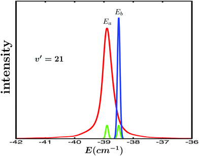
Specifically, the simulations focus on the excitation of the Ne–Br2(B,v′ = 21,n′ = 4) intermolecular resonance (n′ = 4 meaning the fourth excited resonance). The excitation spectrum associated with this resonance is shown in Fig. 1. This profile displays the Lorentzian shape characteristic of an isolated resonance state. The peak of the spectrum is located at the resonance energy E = −38.90 cm−1, and its full width at half maximum is about FWHM = 0.4 cm−1.The goal is to modify the decay behaviour of the Ne–Br2(B,v′ = 21,n′ = 4) resonance, that is, its decay lifetime and the energy-resolved (at the energy E = −38.90 cm−1) asymptotic Br2(B,vf < v′) fragment vibrational state distribution (vf = v′ − 1, v′ − 2, v′ − 3,…) produced upon resonance decay. To this purpose, the control strategy adopted is similar to that used with overlapping resonances,15,35–37 namely to excite two different energies Ea and Eb of the spectrum of Fig. 1 in order to induce interference between them. These two energies are excited by two pulses delayed in time. As previously shown, by varying the delay time between the pulses the interference is controlled, and the enhancement of the resonance lifetime can be optimized.15,35,36 Modification of the asymptotic fragment distribution only requires a sufficiently long delay time between the pulses, without optimization.
The two energies chosen to induce interference are the resonance energy Ea = −38.90 cm−1 and Eb = −38.50 cm−1, both indicated in Fig. 1. The control scheme applies a pump laser field that combines three Gaussian-shaped pulses with the form
ε3(t) = A1e−(t−t1)2/2σ2![[thin space (1/6-em)]](https://www.rsc.org/images/entities/char_2009.gif) cos[ω1(t − t1) + ϕ1] + A2e−(t−t2)2/2σ2 cos[ω1(t − t1) + ϕ1] + A2e−(t−t2)2/2σ2![[thin space (1/6-em)]](https://www.rsc.org/images/entities/char_2009.gif) cos[ω2(t − t2) + ϕ2] + A3e−(t−t3)2/2σ3 cos[ω2(t − t2) + ϕ2] + A3e−(t−t3)2/2σ3![[thin space (1/6-em)]](https://www.rsc.org/images/entities/char_2009.gif) cos[ω2(t − t3) + ϕ3], cos[ω2(t − t3) + ϕ3], | (4) |
Regarding the specific parameters used in ε3(t) in the simulations, for simplicity it is assumed that ϕ1 = ϕ2 = ϕ3 = 0. The amplitudes of the pulses are A1 = A2 = 1.0 × 10⁻⁶ a.u., and A3 = 3A1, which correspond to a maximum pulse intensity of about 3.5 × 10⁴ W cm−2 and 3.2 × 10⁵ W cm−2, respectively, within the weak-field regime. In practice t1 is fixed at a value t1 = 0, and t2 and t3 are varied. Thus, the delay time between the pulses becomes Δt12 = t2 − t1 = t2 and Δt13 = t3 − t1 = t3. The temporal width of all the pulses (related to σ) is the same, and corresponds to a full width at half maximum of FWHM = 200 ps. The spectral profiles of these pulses are shown in Fig. 1 for the two energies Ea and Eb. They are rather narrow and do not overlap in the energy domain. In addition to the simulations applying the ε3(t) field, simulations using a single-pulse field ε1(t) = A1e−(t−t1)2/2σ2![[thin space (1/6-em)]](https://www.rsc.org/images/entities/char_2009.gif) cos[ω1(t − t1) + ϕ1] to excite only the Ea resonance energy were carried out in order to obtain the resonance lifetime and the Br2(B,vf < v′) distribution in the absence of interference. The same values given above were used for the parameters A1, t1, σ, ω1, and ϕ1.
cos[ω1(t − t1) + ϕ1] to excite only the Ea resonance energy were carried out in order to obtain the resonance lifetime and the Br2(B,vf < v′) distribution in the absence of interference. The same values given above were used for the parameters A1, t1, σ, ω1, and ϕ1.
Control of the resonance lifetime is achieved by applying the two first pulses of ε3(t) with different delay times Δt12 in the range −500 ps ≤ Δt12 ≤ 500 ps. For each value of Δt12 the resonance survival probability In′=4(t) = |〈ψn′=4(t)|Φ(t)〉|2 is computed, where ψn′=4(t) is the resonance wave function and Φ(t) is the wave packet created by the two first pulses of ε3(t). Now the corresponding lifetime, τ, is obtained by fitting In′=4(t) to the function38
 | (5) |
The In′=4(t) curves obtained for several values of Δt12 are displayed in Fig. 2(a), along with the survival probability computed when only the resonance energy Ea is excited with the single-pulse field ε1(t). In Fig. 2(b) a typical fit obtained using eqn (5) is also shown. As expected, the single-energy In′=4(t) curve displays no structure, since interference is not possible. The lifetime obtained for this curve with eqn (5) is τsing = 16.0 ps. The two-pulse curves, however, display a pronounced structure of peaks or undulations, which are the signature of quantum interference between the amplitudes excited to the energies Ea and Eb. Actually the different peaks of each curve are separated by the same constant amount of time, which is proportional to the inverse of the energy separation Eb − Ea, as expected from an interference event.
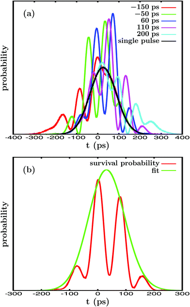 | ||
| Fig. 2 (a) Resonance survival probability In′=4(t) computed when ε3(t) is applied with different delay times Δt12, from Δt12 = −150 ps to Δt12 = 200 ps, between the pulses exciting the Ea and Eb energies. The corresponding In′=4(t) curve obtained when the single-pulse field ε1(t) is applied to excite only the Ea energy is also displayed. (b) In′=4(t) curve calculated for the delay time Δt12 = 40 ps (red line), along with the corresponding fit (green line) obtained by using eqn (5). | ||
Interference between the amplitudes at Ea and Eb requires their simultaneous excitation, and therefore some temporal overlap between the two first pulses of ε3(t).15,36 Thus, the basis of the control scheme applied is the variation of Δt12, because it modifies the temporal overlap between the two first pulses of ε3(t). Varying this overlap implies the variation of the relative amplitudes that are excited to both Ea and Eb, and therefore their mechanism of interference. When interference between the amplitudes at Ea and Eb is modified, the shape of the In′=4(t) curve changes as well, as shown in Fig. 2(a), which leads to the variation of the associated resonance lifetime.
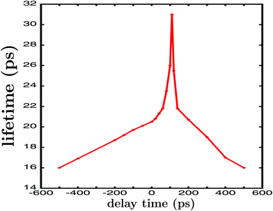
By applying eqn (5) the resonance lifetime is calculated for the different values of Δt12, and the results are plotted in Fig. 3. The figure shows that for very large delay times |Δt12| = 500 ps the lifetime found is τ = 16.0 ps, the same value obtained when the single-pulse field ε1(t) is applied. For large |Δt12| there is no temporal overlap between the two first pulses of ε3(t), and thus no interference between Ea and Eb is possible, leading to the same τ obtained with ε1(t). However, when |Δt12| decreases, the overlap between the pulses becomes nonzero and interference between the amplitudes at Ea and Eb takes place. The result is a gradual enhancement of the resonance lifetime, which increases from τ = 16.0 ps to τ = 31.0 ps at Δt12 = 110 ps, nearly twice the value obtained in the absence of interference.
In a previous study35 the variation of the resonance lifetime was analyzed by changing both the laser fields and the delay times between the pulses, in a framework of overlapping resonances, and such analysis provided very useful insight about how the interference mechanism works. The shape of the curve of Fig. 3 is similar to those found for overlapping resonances,15,35 indicating that the mechanism of interference operates similarly in the lifetime enhancement. In this sense, the value of Δt12 at which maximum lifetime enhancement is achieved is determined by the maximization of the intensity of interference between the amplitudes of Ea and Eb.35 And the achievement of maximum interference intensity depends on reaching enough temporal overlap between the two pulses (albeit not necessarily the maximum overlap, occurring at Δt12 = 0), but such that the mechanism of interference between the amplitudes excited at Ea and Eb is optimized. Such optimization of the interference is what determines the maximum enhancement of the resonance lifetime achieved (τ = 31.0 ps) and the value of Δt12 at which it takes place (Δt12 = 110 ps in this case).35,36 It is noted, however, that complete optimization of the laser field (involving going beyond just varying Δt12, and changing the Gaussian shape of the pulses) in order to fully maximize the resonance lifetime enhancement has not been pursued, and thus the enhancement currently achieved could be increased further.
The next goal is to modify the other resonance properties that determine the outcome of a resonance-mediated molecular process, namely the energy-resolved asymptotic fragment distribution. In the present case it corresponds to the Br2(B,vf < v′) fragment distribution produced upon predissociation at the resonance energy Ea = −38.9 cm−1. To this end, the third pulse of ε3(t) is used to excite the Eb energy, similar to that performed previously with the second pulse. The difference now is that the first and the third pulse will not overlap in time, and the delay time Δt13 between them will be much longer than Δt12. The reason for a longer Δt13 is to allow enough time for the first amplitude excited at Ea to decay completely and to reach the asymptotic regime of the fragment distribution produced. Thus, by exciting amplitude to Eb, quantum interference is induced between this and the asymptotic decayed amplitude initially excited to Ea by the first pulse of ε3(t).36,37 In the present simulations a long enough delay time Δt13 = 1500 ps has been chosen, and in Fig. 4(a) the temporal profile of the ε3(t) field applied is displayed, with Δt12 = 110 ps, A1 = A2, and A3 = 3A1.
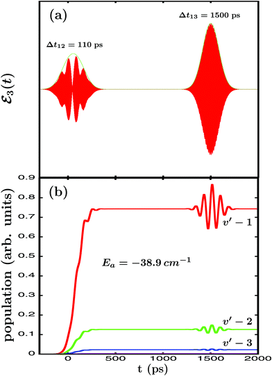 | ||
| Fig. 4 (a) Temporal profile (red line) along with its envelope (green line) of the ε3(t) laser field applied to excite the Ne–Br2(B,v′ = 21, n′ = 4) resonance, with Δt12 = 110 ps in this case, and Δt13 = 1500 ps. (b) Energy-resolved Br2(B,vf) fragment vibrational populations in the vf = v′ − 1,…, v′ − 4 final vibrational state produced upon predissociation of Ne–Br2(B,v′ = 21, n′ = 4), associated with the resonance energy Ea = −38.9 cm−1, when the ε3(t) field of Fig. 4(a) is applied. All the vibrational vf populations are labeled in the figure except vf = v′ − 4, which is very small. | ||
In Fig. 4(b) the energy-resolved Br2(B,vf) fragment vibrational populations in the vf = v′ − 1,…,v′ − 4 final vibrational state associated with the Ea resonance energy are shown. The different populations display a clear modification in the asymptotic time regime when the third pulse of ε3(t) is applied to excite the Eb energy. Such a modification manifests itself in the form of undulations that reflect the interference taking place between the amplitudes excited at both energies. This interference occurs between the asymptotic amplitude at the Ea energy and the amplitude excited at the Eb energy, which temporarily populates the continuum fragment states at Ea.36,37 The interference effect is increasingly more intense as the vf population is larger in magnitude, because the larger is the asymptotic amplitude the more intense will be the interference terms. In this sense it is noted that the second pulse of ε3(t) also causes an interference effect on the vibrational populations of Fig. 4(b) around Δt12 = 110 ps, although being much weaker since A2 = A3/3. Once the third pulse is over and the amplitude excited at Eb has decayed completely, the asymptotic populations converge back to the values previous to the application of the third pulse. The implication is that the modifications caused by interference in the fragment distribution cannot be observed asymptotically in the same vibronic state (Br2(B,vf) in our case) where they are produced. This, however, does not prevent an effective control of the fragment distribution and its observation, if the fragments are detected or moved to other vibronic states of interest (applying a further laser pulse) while the interference effect takes place.
The above results demonstrate numerically that by inducing quantum interference between amplitudes at two different energies by applying a simple laser field like ε3(t) of eqn (4), extensive control over the decay lifetime and the asymptotic fragment distribution produced upon decay of an isolated resonance can be achieved in the weak-field regime. In the following the formal theory underlying those results and the present control scheme is developed.
Let Ĥ be the total Hamiltonian of a general molecular system that supports isolated resonances (Ne–Br2(B,v′) would be an example of such a general system). Following the discussion on the decay of a resonance state of Cohen-Tannoudji et al.,43 we can write Ĥ as Ĥ = Ĥ0 + W, where Ĥ0 is a zeroth-order Hamiltonian and W is a coupling. The spectrum of Ĥ0 consists of a set of discrete bound states χi (located in the interaction region) with associated energies Ei, and a set of continuum states φE,m (associated with the product fragments in the asymptotic region) with associated energies E, and m being a global label for the fragment internal states. When W = 0 the χi states are true bound states, but when W ≠ 0, χi become resonances ψi that decay to the continuum of φE,m states. These states fulfill the orthogonality relationship
| 〈χi|χi〉 = δij,〈φE′,m′|φE,m〉 = δm′mδ(E′ − E),〈χi|φE,m〉 = 0, | (6) |
 | (7) |
Let us now focus on one of the isolated resonances of our general molecular system. By applying a single-pulse field like ε1(t) to excite the resonance energy Ea, a wave packet ξEa(t) is created
 | (8) |
 and
and  . Thus, when two pulses are applied to excite the Ea and Eb energies to induce interference between them, the following wave packet is created
| Φ(t) = ξEa(t) + ξEb(t), | (9) |
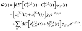 | (10) |
A resonance wave function ψi can also be expressed in terms of the stationary eigenstates ψE as
 | (11) |
Thus, the resonance survival probability Ii(t) is
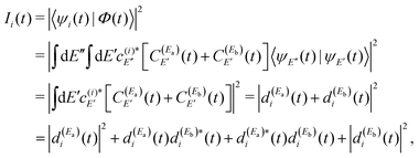 | (12) |
 , with α = a,b.
The term  of eqn (12) is the survival probability that would be obtained if a single resonance energy Ea was excited with the single-pulse field E1(t) (i.e., the plain curve of Fig. 2(a), with associated lifetime τsing = 16.0 ps). The three additional terms of eqn (12) arise from the excitation of amplitude at energy Eb by the second pulse of ε3(t), and its interference with the resonance amplitude excited at Ea. Such terms associated with the interference are the ones that cause the undulations of the In′=4(t) curves of Fig. 2(a). As mentioned above, the requirement for these terms to be nonzero is that the amplitudes
  and
and  must be generated simultaneously at Ea and Eb, respectively, which implies the temporal overlap to some extent of the two pulses exciting those energies. When the delay time Δt12 between the pulses is varied, the range of temporal overlap between them is modified, changing the relative
  and
and  amplitudes excited simultaneously. This causes a variation of the interference terms of eqn (12) in a controlled manner, which leads to a change in the shape of Ii(t) (see Fig. 2(a)), and thus also in the associated lifetime (as shown in Fig. 3). In brief, interference induces a new decay mechanism with a longer lifetime that replaces the intrinsic decay mechanism, in which a transfer of amplitude back and forth between the two energies takes place.44Eqn (11) reflects the fact that a resonance state ψi possesses a nonzero energy width. This finite width is what makes possible interference of the resonance with itself, when a wave packet Φ(t) containing different energies within this width (essentially Ea and Eb) is created with the two pulses of the field. This is the key aspect of the present weak-field control scheme of the isolated resonance behavior.
Regarding the fragment state distribution produced upon resonance decay, the asymptotic probability associated with the fragment state φE,m can be expressed as
 | (13) |
 | (14) |
 | (15) |
 amplitude, and its interference with the asymptotic amplitude
  previously excited to Ea. Such interference is what causes the long-time undulations displayed in the vibrational populations of Fig. 4(b). Indeed, the first term of eqn (15),
  , is generated when only the Ea energy is excited by the first pulse of ε3(t) (or by the single-pulse field ε1(t)). The three additional terms arising from the excitation to Eb “dress” the first term, producing the interference-induced modification of the fragment distribution in a similar way to the survival probability of eqn (12). The difference with the resonance lifetime control is that now the two pulses are not required to overlap in time, because the amplitude excited to Ea will remain all the time in the continuum fragment states after decay.
The mechanism of interference in this case is the following. After the amplitude excited to Ea has decayed to the continuum fragment states, becoming asymptotic, the third pulse of ε3(t) pumps amplitude to the Eb energy. When this latter amplitude decays, it spreads and redistributes temporarily among all the φE,m continuum states accessible by the resonance state within its energy width, including those associated with the Ea energy, φEa,m. This generates temporarily the amplitude  appearing in the last three terms of eqn (15) that produce the interference effect in the fragment distribution.36,37 The temporary dispersion of the amplitude excited by the third pulse among different φE,m asymptotic states within a range of energy that includes the φEa,m fragment states is due to the uncertainty principle. Once the third pulse of ε3(t) is over and all the amplitude excited to Eb has decayed completely to the appropriate φEb,m fragment states, producing a distribution at energy Eb, interference ceases and the asymptotic distribution at Ea converges again to
  . Since the interference terms of eqn (15) appear as long as the amplitude ξEb(t) (or equivalently
  ) is created by the third pulse of ε3(t), it becomes clear that this can be done at any asymptotic time as long as desired, and as many times as desired (using further successive pulses after the third one in the laser field).
The above general equations, and specifically eqn (12) and (15), which govern the resonance survival probability and product fragment distribution, respectively, provide the formal support to the results of the numerical simulations shown in Fig. 2–4. It is stressed that in the derivation of these equations no assumption is made on the nature or type of the molecular system that originates or supports the isolated resonance under control. Therefore these equations are valid for any isolated resonance, regardless of the origin of the system featuring the resonance. The consequence is that the application of the present control scheme behind these equations is general and universal to any molecular system featuring isolated resonance states, thus making possible the control of both the duration and the outcome of any resonance-mediated molecular process.
4 Conclusions
In conclusion, this study demonstrates both numerically and mathematically the possibility to control extensively the dynamical decay behavior of an isolated resonance state, which involves the resonance decay lifetime and the asymptotic fragment state distribution produced upon resonance decay. The weak-field control scheme applied is based on inducing quantum interference between amplitudes excited at two different energies of the resonance line shape, namely the resonance energy and an additional energy. Control is achieved by using a simple laser field consisting of a combination of three pulses with a delay time between them. The first pulse excites the resonance energy, the second pulse excites the second energy in order to control the decay lifetime, and finally the third pulse excites again the second energy at a much longer delay time in order to control the asymptotic fragment distribution. The key aspect of the control scheme is to exploit the property of the resonance state that involves possessing a nonzero energy width, which makes it possible that the resonance state may interfere with itself, and thus allows interference between the amplitudes excited at the two energies of the resonance width used in the scheme. The formal equations developed demonstrate that the application of the scheme is universal to any resonance-mediated molecular process, in order to control both its duration and decay outcome.Conflicts of interest
There are no conflicts of interest to declare.Acknowledgements
This work was funded by the Ministerio de Economía y Competitividad (MINECO, Spain), Grants No. CTQ2015-65033-P and PGC2018-096444-B-100. The Centro de Supercomputación de Galicia (CESGA, Spain) is acknowledged for the use of its resources.References
- D. Tannor and S. Rice, J. Chem. Phys., 1985, 83, 5013–5018 CrossRef CAS.
- P. Brumer and M. Shapiro, Chem. Phys. Lett., 1986, 126, 541–546 CrossRef CAS.
- A. Assion, T. Baumert, M. Bergt, T. Brixner, B. Kiefer, V. Seyfried, M. Strehle and G. Gerber, Science, 1998, 282, 919–922 CrossRef CAS PubMed.
- P. Anfinrud, R. de Vivie-Riedle and V. Engel, Proc. Natl. Acad. Sci. U. S. A., 1999, 96, 8328–8329 CrossRef CAS PubMed.
- S. A. Rice and M. Zhao, Optical Control of Molecular Dynamics, Wiley-Interscience, 2000 Search PubMed.
- R. J. Levis, G. M. Menkir and H. Rabitz, Science, 2001, 292, 709–713 CrossRef CAS PubMed.
- E. Skovsen, M. Machholm, T. Ejdrup, J. Thϕgersen and H. Stapelfeldt, Phys. Rev. Lett., 2002, 89, 133004 CrossRef PubMed.
- C. Daniel, J. Full, L. González, C. Lupulescu, J. Manz, A. Merli, S. Vajda and L. Wöste, Science, 2003, 299, 536–539 CrossRef CAS PubMed.
- M. Shapiro and P. Brumer, Principles of the Quantum Control of Molecular Processes, Wiley-Interscience, 2003 Search PubMed.
- B. J. Sussman, D. Townsend, M. I. Ivanov and A. Stolow, Science, 2006, 314, 278–281 CrossRef CAS PubMed.
- G. Katz, M. A. Ratner and R. Kosloff, Phys. Rev. Lett., 2007, 98, 203006 CrossRef PubMed.
- M. P. A. Branderhorst, P. Londero, P. Wasytcyk, C. Brif, R. L. Kosut, H. Rabitz and I. A. Walmsley, Science, 2008, 320, 638–643 CrossRef CAS PubMed.
- A. B. Henson, S. Gersten, Y. Shagam, J. Narevicius and E. Narevicius, Science, 2012, 338, 234–238 CrossRef CAS PubMed.
- A. García-Vela, J. Chem. Phys., 2012, 136, 134304 CrossRef PubMed.
- A. García-Vela, J. Phys. Chem. Lett., 2012, 3, 1941–1945 CrossRef.
- F. Calegari, et al. , Science, 2014, 346, 336–339 CrossRef CAS PubMed.
- M. E. Corrales, J. González-Vázquez, G. Balerdi, I. R. Solá, R. de Nalda and L. Bañares, Nat. Chem., 2014, 6, 785–790 CrossRef CAS PubMed.
- R. Cireasa, et al. , Nat. Phys., 2015, 11, 654–658 Search PubMed.
- A. Serrano-Jiménez, L. Bañares and A. García-Vela, Phys. Chem. Chem. Phys., 2019, 21, 7885–7893 RSC.
- R. T. Skodje, D. Skouteris, D. E. Manolopoulos, S. H. Lee, F. Dong and K. Liu, Phys. Rev. Lett., 2000, 85, 1206–1209 CrossRef CAS PubMed.
- P. S. Chistopher, M. Shapiro and P. Brumer, J. Chem. Phys., 2005, 123, 064313 CrossRef PubMed.
- M. Qiu, et al. , Science, 2006, 311, 1440–1443 CrossRef CAS PubMed.
- D. Gerbasi, A. S. Sanz, P. S. Chistopher, M. Shapiro and P. Brumer, J. Chem. Phys., 2007, 126, 124307 CrossRef CAS PubMed.
- J. B. Kim, et al. , Science, 2015, 349, 510–513 CrossRef CAS PubMed.
- W. Shiu, J. J. Lin and K. Liu, Phys. Rev. Lett., 2004, 92, 103201–1-4 CrossRef PubMed.
- O. Atabek, R. Lefebvre, M. Lepers, A. Jaouadi, O. Dulieu and V. Kokoouline, Phys. Rev. Lett., 2011, 106, 173002 CrossRef CAS PubMed.
- S. Chefdeville, et al. , Phys. Rev. Lett., 2012, 109, 023201 CrossRef PubMed.
- T. Westermann, et al. , Angew. Chem., Int. Ed., 2014, 53, 1122–1126 CrossRef CAS PubMed.
- S. N. Vogels, et al. , Science, 2015, 350, 787–790 CrossRef CAS PubMed.
- A. García-Vela and N. E. Henriksen, J. Phys. Chem. Lett., 2015, 6, 824–829 CrossRef PubMed.
- A. Bergeat, J. Onvlee, C. Naulin, A. van der Avoird and M. Costes, Nat. Chem., 2015, 7, 349–353 CrossRef CAS PubMed.
- C. Naulin and M. Costes, Chem. Sci., 2016, 7, 2462–2469 RSC.
- A. García-Vela, Chem. Sci., 2017, 8, 4804–4810 RSC.
- S. Bhattacharyya, S. Mondal and K. Liu, J. Phys. Chem. Lett., 2018, 9, 5502–5507 CrossRef CAS PubMed.
- A. García-Vela, Phys. Chem. Chem. Phys., 2018, 20, 3882–3887 RSC.
- A. García-Vela, Phys. Chem. Chem. Phys., 2019, 21, 7491–7501 RSC.
- A. García-Vela, Phys. Rev. Lett., 2018, 121, 153204–1-6 CrossRef PubMed.
- J. A. Cabrera, C. R. Bieler, B. C. Olbricht, W. E. van der Veer and K. C. Janda, J. Chem. Phys., 2005, 123, 054311–1-8 CrossRef PubMed.
- M. A. Taylor, J. M. Pio, W. E. van der Veer and K. C. Janda, J. Chem. Phys., 2010, 132, 104309 CrossRef PubMed.
- A. García-Vela and K. C. Janda, J. Chem. Phys., 2006, 124, 034305 CrossRef PubMed.
- A. García-Vela, J. Chem. Phys., 2008, 129, 094307 CrossRef PubMed.
- A. García-Vela, Phys. Chem. Chem. Phys., 2015, 17, 29072–29078 RSC.
- C. Cohen-Tannoudji, B. Diu and F. Laloë, Quantum Mechanics, John Wiley and Sons, 1977 Search PubMed.
- A. García-Vela, J. Phys. Chem. A, 2019, 123, 7394–7400 CrossRef PubMed.
| This journal is © the Owner Societies 2020 |

