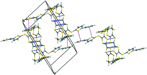
 Open Access Article
Synthesis and structures of polyiodide radical cation salts of donors combining tetrathiafulvalene with multiple thiophene or oligo-thiophene substituents†
Jonathan
Short
,
Toby J.
Blundell
 ,
Songjie
Yang
,
Onur
Sahin
,
Yiana
Shakespeare
,
Emma L.
Smith
,
Songjie
Yang
,
Onur
Sahin
,
Yiana
Shakespeare
,
Emma L.
Smith
 ,
John D.
Wallis
 * and
Lee
Martin
 *
*
School of Science and Technology, Nottingham Trent University, Clifton Lane, Nottingham, NG11 8NS, UK. E-mail: lee.martin@ntu.ac.uk; john.wallis@ntu.ac.uk
First published on 16th September 2020
Abstract
A series of TTF and EDT-TTF derived donors bearing thiophene, bithiophene and terthiophene side chains is described, from which a group of six radical cation salts with polyiodide ions were formed and structurally characterised. Typically, they contain complex networks of pentaiodide or triiodide anions or both, in some cases including further iodine, with networks of eight, ten, twelve or sixteen iodine atoms. Donor monocations form face-to-face pairs, but tetrakis-substituted donors are slipped along their main axis so the donor side chains can wrap around each other.
Introduction
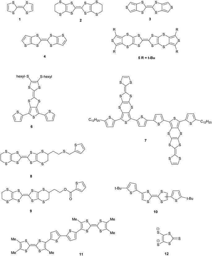
Derivatives of both the organosulfur donor tetrathiafulvalene (TTF) 1, and also thiophene-based materials, especially oligomers and polymers, are well known for exhibiting electrical conductivity, often after partial oxidation.1,2 The TTF system has been extended to give BEDT-TTF 2 whose radical cation salts have provided conductors, semi-conductors and superconductors.3 New materials with conductive properties have been prepared by combining either TTF or the BEDT-TTF system with thiophene or oligothiophenes in a number of ways. Ring fusion leads to compounds such as 3–5 (Scheme 1). Spin ladders have been prepared from 3 and 4, and donor 3 has shown promising properties for organic transistors, while 5 has been oxidized up to its tetracation.4–6 Skabara et al. have built molecules such as 6 and 7 which combine terthiophene and sexithiophene with one or two TTF-based units fused along the backbone,7 as well as derivatives of dithiopheneTTF 3 with four oligothiophene chains.8 Several BEDT-TTF derivatives containing an isolated thiophene in a side chain have been reported, e.g.8 and 9, and the latter investigated for its suitability for use in transistors.9 To maintain the possibility of conjugation between TTF and thiophene, the two systems have been linked with a single bond as in 10 and 11.10 The former is particularly interesting as it shows a large phototransistor response to light (λ = 525 nm) attributed to charge transfer from TTF to the thiophene. We are interested in molecules where these two systems are linked with a sulfur atom. New chemistry developed by Shao et al. for installation of a wide variety of aryl groups on to the thiolate groups of 1,3-dithiole-dithiolate 12 has opened up the route to prepare such compounds.11 Here we report the synthesis of TTF materials 15A–15E, 17A, 19A and 19C–19E containing thiophene, 2,2′-bithiophene or 2,2′:5′,2′′-terthiophene side chains linked to the TTF through sulfur (Scheme 2), along with their first charge transfer salts. Most compounds involve links to the position adjacent to heterocyclic sulfur, except for 15B where the substitution is to the 3-position of thiophene. Compound 15A, with four thiophen-2-yl groups, was reported by Shao,11 along with the formation of a supramolecular framework by its radical cation salt with a Keggin-type phosphonomolybdate anion.12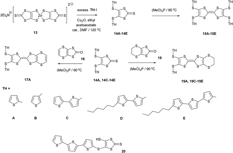 | ||
| Scheme 2 Synthetic routes to new donor molecules. Side chains (TH) are designated by letters A to E. | ||
Discussion
Synthesis of donors
1,3-Dithiole-2-thiones 14A–14C, bearing two thiophen-2-yl, thiophen-3-yl or bithiophen-2-yl groups, were prepared in high yield (74–80%) by reaction of 13, the zinc complex of the dithiolate 12, with the appropriate iodo-thiophene or -bithiophene. The reaction is catalysed by copper(I) oxide and ethyl acetoacetate following the methodology of Shao (Scheme 2). However, reaction of 13 with 2-iodo-(5,2′;5′2′′)-terthiophene led to the precipitation of the thione 20 with just one terthiophene group attached. This suggests that this is the limiting point in extending the synthesis to higher unsubstituted polythiophenes. To increase the solubility of the monosubstituted thione and the subsequent donors, the thiones 14D–14E with hexyl side chains on the bi- or terthiophene residue were prepared in 61 and 89% yields. This followed the same methodology using zinc complex 13 and the appropriate iodoaromatic.13,14The disubstituted thiones 14A–14E were converted to tetrasubstituted TTF donors 15A–15E by self-coupling of each thione in trimethyl phosphite in good yields (58–90%). Disubstituted derivatives of the EDT-TTF system, with an ethylenedithio bridge at one end of the TTF system, 19A and 19C–19E, were prepared by cross-coupling of the particular thione with oxo compound 18, in 39–49% yields. Donor 17A, with an vinylenedithio bridge on the TTF system, was prepared by cross-coupling of thione 14A with the vinyl bridged oxo compound 1615 in 23% yield.
Cyclic voltammetry studies on the donors confirmed their ready oxidation with a pair of reversible redox peaks (Table 1 and Fig. S2 in ESI†). For the tetrasubstituted TTF donors 15A–15D the mid-point redox peaks were in the ranges 0.57–0.62 V and 0.94–1.02 V. For the disubstituted donor with the conjugated vinylenedithio bridge 17A these mid-point potentials are at similar positions of 0.63 and 1.02 V, but for the disubstituted donors with the –CH2CH2– bridge, 19A and 19C–19E, these two potentials are a little lower at ca. 0.54 and 0.94 V. The donors which carry bithiophene units also show an irreversible oxidation peak in the range 1.45–1.50 V, while donor 19E with terthiophene units show a lower irreversible oxidation peak at 1.15 V. This extra oxidation in 15C and 19C which contain bithiophenes may relate to the bithiophenes of two separate donors adding to one another as in the polymerisation of polythiophenes. For 15D and 19D, the bithiophenes are end-capped with hexyl groups so this is not possible. A bond may have formed between the two bithiophenes of a single donor. A full electrochemical investigation will need to be made on these and similar compounds.
| Donor | E 1 (V) | E 2 (V) | E 3 (V) |
|---|---|---|---|
| a Measured in 0.1 M tetrabutylammonium hexafluorophosphate in DCM at 20 °C, substrate concentrations ca. 0.01 mM, and scan rate of 0.1 V s−1. b Full scans shown in the ESI.† c 15E too insoluble to get a response. d Not reversible. If potential window set 0–1.1 V the E1 and E2 peaks remain reversible. | |||
| 15A | 0.59 | 0.97 | |
| 15B | 0.60 | 0.94 | |
| 15C | 0.62 | 1.02 | 1.50d |
| 15D | 0.57 | 0.99 | 1.45d |
| 17A | 0.63 | 1.02 | |
| 19A | 0.54 | 0.94 | |
| 19C | 0.54 | 0.95 | 1.46d |
| 19D | 0.55 | 0.96 | 1.44d |
| 19E | 0.54 | 0.94 | 1.15 |
Preparation and properties of radical cation salts
Radical cation salts were prepared by slow diffusion of a solution of iodine in hexane into a solution of the donor in dichloromethane. Crystalline products were obtained with donors 15A and 15B carrying four thiophene groups, and the disubstituted donors 17A, 19A (two polymorphs) and 19C. The latter was the only complex obtained with a donor bearing bithiophene groups. Donor 15E with four 5′′-hexyl-terthiophene groups did not appear to react with iodine, but donor 19E with two such groups gave a black amorphous deposit. Six crystalline products were characterised by X-ray crystallography (Table 2).| 15A.I5 | 15B.I5 | 17A.I3.1.5I2 | |
|---|---|---|---|
| Formula | C22H12S12I5 | C22H12S12I5 | C16H8S10I6 |
| M r/g mol−1 | 1295.54 | 1295.4 | 1282.22 |
| Temp/K | 150 | 150 | 150 |
| Crystal system | Monoclinic | Monoclinic | Monoclinic |
| Space group | P21/n | P21/n | C2/c |
| a/Å | 13.5430(2) | 13.6653(3) | 11.5148(3) |
| b/Å | 16.3848(3) | 16.1342(4) | 18.1689(5) |
| c/Å | 16.6552(3) | 17.0452(4) | 29.3477(12) |
| α/° | 90 | 90 | 90 |
| β/° | 102.5943(19) | 105.183(2) | 91.157(3) |
| γ/° | 90 | 90 | 90 |
| V/Å3 | 3606.86(12) | 3626.92(15) | 6138.6(3) |
| Z | 4 | 4 | 8 |
| ρ/g cm−3 | 2.386 | 2.371 | 2.775 |
| R 1 [I > 2σ(I)] | 0.0354 | 0.0492 | 0.0979 |
| wR [all data] | 0.0695 | 0.1181 | 0.1835 |
| CCDC No. | 2011618 | 2011619 | 2011620 |
| (19A)2.I5.I3 | 19A.I3 | 19C.I5.0.5I2 | |
|---|---|---|---|
| Formula | C32H20S20I8 | C16H10S10I3 | C24H14S12I6 |
| M r/g mol−1 | 1024.39 | 903.54 | 1448.47 |
| Temp/K | 150 | 293 | 150 |
| Crystal system | Monoclinic | Triclinic | Triclinic |
| Space group | P21 |
P![[1 with combining macron]](https://www.rsc.org/images/entities/char_0031_0304.gif) |
P![[1 with combining macron]](https://www.rsc.org/images/entities/char_0031_0304.gif) |
| a/Å | 9.0576(10) | 11.8075(2) | 10.2097(6) |
| b/Å | 28.632(2) | 14.6651(3) | 10.9057(6) |
| c/Å | 10.5799(10) | 16.9675(3) | 17.3954(12) |
| α/° | 90 | 92.604(2) | 90.663(5) |
| β/° | 100.212(10) | 106.484(2) | 102.294(6) |
| γ/° | 90 | 107.727(2) | 93.878(5) |
| V/Å3 | 2700.3(5) | 2655.43(9) | 1887.5(2) |
| Z | 2 | 4 | 2 |
| ρ/g cm−3 | 2.520 | 2.260 | 2.549 |
| R 1 [I > 2σ(I)] | 0.0718 | 0.0399 | 0.0620 |
| wR [all data] | 0.1608 | 0.0887 | 0.1011 |
| CCDC No. | 2011621 | 2011622 | 2011623 |
Complexes of donors 15A and 15B
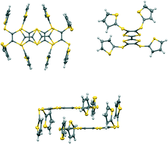
Donors 15A and 15B are very similar in structure and differ only in the point of attachment of the four thiophenes to the TTF-tetrathiol unit, alpha or beta to the thiophene sulfur. They form very similar complexes of formula: donor+.I5− with comparable unit cells in the monoclinic space group P21/n with one donor monocation and one I5− anion crystallographically unique (Table 2).In the crystal structure of 15A.I5 the donors form centrosymmetric face-to-face radical cation pairs. At one end of the donor monocation the two thiophene groups are directed out to the side of the TTF (torsion angles, S(TTF)–C(TTF)–S–C(thiophene): 0.1 and 9.0°), while at the other end they are directed out of the donor plane but to different degrees (torsion angles, S(TTF)–C(TTF)–S–C(thiophene): 47.9 and 75.4°) (Fig. 1). Within the radical cation pair one TTF unit is slipped along the main axis by ca. 3.7 Å relative to the other. This allows the two thiophene groups projected up from the TTF to wrap around the end of the other donor which has the thiophene rings projected to either side (Fig. 1). This paired motif was also observed in the radical cation salt of 15A with a phosphonomolybate ion.12 This isolates the TTF sulfur atoms from contacts with other TTF units. The six S⋯S contacts between the tetrathio-TTF moieties of the radical cation pair lie in range 3.3727(15)–3.5531(16) Å (Table 3). The overlapping thiophene groups are tightly packed together, each linker sulfur atom makes a short contact to a thiophene ring of the other donor (S⋯S(thiophene): 3.439(4), S⋯C(thiophene): 3.472(7) and 3.48(6) Å) and there are further contacts between overlapping thiophene rings: S⋯C: 3.36(7)–3.521(16) and C⋯C: 3.47(8)–3.585(18) Å (Table 3). There is rotational disorder about the S–C(thiophene) bond for the two thiophene groups which are projected out to the side of the TTF, in ratios 3![[thin space (1/6-em)]](https://www.rsc.org/images/entities/char_2009.gif) :
:![[thin space (1/6-em)]](https://www.rsc.org/images/entities/char_2009.gif) 2 and 2
2 and 2![[thin space (1/6-em)]](https://www.rsc.org/images/entities/char_2009.gif) :
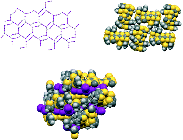
:![[thin space (1/6-em)]](https://www.rsc.org/images/entities/char_2009.gif) 1 for the two rings. Such disorder, in which a thiophene ring is rotated by 180° about the S–C(thiophene) bond is quite common for thiophene and polythiophene derivatives, since both orientations of the ring have similar steric demands. This mode of disorder occurs in the polyiodide salts of 15B, 19A (monoclinic phase) and 19C discussed here. The radical cation pairs are packed in layers positioned between networks of pentaiodide ions, which contain rings composed of eight iodine atoms and sixteen iodine atoms (Fig. 2, Table 4). Thiophene rings penetrate the pentaiodide layers. There are S⋯I contacts involving the TTFs in the range 3.70–3.80 Å, and involving the two sulfur positions of a disordered thiophene ring of ca. 3.67 Å. The conformations and mode of packing of cation pairs and the separation between layers means there is no good pathway for electrical conduction. Indeed measurement of resistivity for all six crystalline radical-cation salts discussed here showed that all of them have a room temperature resistance too high to be measured by the multimeter.
1 for the two rings. Such disorder, in which a thiophene ring is rotated by 180° about the S–C(thiophene) bond is quite common for thiophene and polythiophene derivatives, since both orientations of the ring have similar steric demands. This mode of disorder occurs in the polyiodide salts of 15B, 19A (monoclinic phase) and 19C discussed here. The radical cation pairs are packed in layers positioned between networks of pentaiodide ions, which contain rings composed of eight iodine atoms and sixteen iodine atoms (Fig. 2, Table 4). Thiophene rings penetrate the pentaiodide layers. There are S⋯I contacts involving the TTFs in the range 3.70–3.80 Å, and involving the two sulfur positions of a disordered thiophene ring of ca. 3.67 Å. The conformations and mode of packing of cation pairs and the separation between layers means there is no good pathway for electrical conduction. Indeed measurement of resistivity for all six crystalline radical-cation salts discussed here showed that all of them have a room temperature resistance too high to be measured by the multimeter.
| Contact type | 15A | 15B |
|---|---|---|
| S⋯S, between TTFs | 3.3727(0.0015) | 3.4311(16) |
| S⋯S, TTF to linker –S– | 3.4108(15), 3.5531(16) | 3.3783(16) 3.5450(18) |
| Thiophene to linker –S– | 3.439(4) S⋯S | 3.539(12), 3.77(5), 3.36(6), 3.53(2) S⋯C |
| 3.472(7), 3.48(6) S···C | ||
| Inter-thiophene in donor pair | 3.67(5) S⋯S | 3.636(11) S⋯C |
| 3.36(7) S⋯C | 3.567(6) S⋯C | |
| 3.36(7) S⋯C | 3.54(3) S⋯C | |
| 3.521(16) S⋯C | 3.38(3) C⋯C | |
| 3.47(8) C⋯C | 3.43(6) C⋯C | |
| 3.554(9) C⋯C | 3.48(9) C⋯C | |
| 3.585(18) C⋯C | ||
| Shortest S⋯I from TTF | 3.7026(12) | 3.7201(12) |
| 3.7204(11) | 3.7775(11) | |
| 3.7511(11) | 3.7456(12) | |
| 3.7920(11) | ||
| Shortest S⋯I from linker S | 3.8776(13) | 3.8573(12) |
| 3.7934(11) | 3.8279(13) | |
| S⋯I from thiophene S | 3.672(8) | 3.8087(17) |
| 3.671(4) | 3.851(2) | |
| 3.78(2) | 3.870(17) | |
| 3.8690(19) | 3.888(3) |
| I5−⋯I5− end/end/Å | I5−⋯I5− end/middle/Å | I5−⋯I3− end/end/Å | I5−⋯I2 middle to I2/Å | ||
|---|---|---|---|---|---|
| 15A.I5 | 3.8655(6) | 3.4084(6) | — | — | |
| 15B.I5 | 3.9327(5) | 3.5541(6) | — | — | |
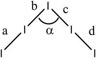
| (19A)2.I3.I5 | — | — | 3.531(2)/3.904(2) | — | |
| 19C.I5.0.5I2 | 3.5713(10) | — | — | 3.4236(11) | |
The corresponding complex from donor 15B adopts a very similar crystal structure (Fig. 3) with the main differences being that all four thiophene rings have a degree of rotational disorder (range: 73![[thin space (1/6-em)]](https://www.rsc.org/images/entities/char_2009.gif) :
:![[thin space (1/6-em)]](https://www.rsc.org/images/entities/char_2009.gif) 27 to 88
27 to 88![[thin space (1/6-em)]](https://www.rsc.org/images/entities/char_2009.gif) :
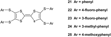
:![[thin space (1/6-em)]](https://www.rsc.org/images/entities/char_2009.gif) 12), and there are some small changes to the pentaiodide network (Table 4). Indeed, the structure of the pentaiodide ion can be considered as an iodine molecule forming a halogen bond to a triiodide ion (Table 4).16 For these two salts this halogen bond would be 3.2565(6) Å long, with an I–I–Î⋯I–I angle of 95.6°, in 15A, and 3.1808(6) Å long, with an angle of 97.3°, in 15B. Some comparisons of contacts in 15A.I5 and 15B.I5 are shown in Table 4. A wide range of polyiodide networks have been reported, in particular, though not exclusively, with nitrogen containing cations.16,17 Shao has reported a very similar polyiodide complex 22.I5 where the thiophenes in 15A and 15B are replaced by 4-fluorophenyl groups (Scheme 3) (vide infra) and the radical cation pair adopts a similar structure.18 The tetraphenyl analogue 21 also forms a pentaiodide salt, containing the same structural motif for the radical cation pair but the pentaiodide anions are organised “end-to-end” to form a chain.19
12), and there are some small changes to the pentaiodide network (Table 4). Indeed, the structure of the pentaiodide ion can be considered as an iodine molecule forming a halogen bond to a triiodide ion (Table 4).16 For these two salts this halogen bond would be 3.2565(6) Å long, with an I–I–Î⋯I–I angle of 95.6°, in 15A, and 3.1808(6) Å long, with an angle of 97.3°, in 15B. Some comparisons of contacts in 15A.I5 and 15B.I5 are shown in Table 4. A wide range of polyiodide networks have been reported, in particular, though not exclusively, with nitrogen containing cations.16,17 Shao has reported a very similar polyiodide complex 22.I5 where the thiophenes in 15A and 15B are replaced by 4-fluorophenyl groups (Scheme 3) (vide infra) and the radical cation pair adopts a similar structure.18 The tetraphenyl analogue 21 also forms a pentaiodide salt, containing the same structural motif for the radical cation pair but the pentaiodide anions are organised “end-to-end” to form a chain.19
Complexes of unsymmetrical donors 17A, 19A and 19C
Donors 17A, 19A and 19C are closely related and have just two side chains: 17A and 19A with two thiophenes and 19C with two bithiophenes. The latter two donors have an ethylene bridge at one end, but donor 17A differs from donor 19A by having a C(H)![[double bond, length as m-dash]](https://www.rsc.org/images/entities/char_e001.gif) C(H)– bridge rather than and a –CH2CH2– bridge. All three formed complexes on reaction with iodine, with 19A forming two complexes of different stoichiometries, (19A)2.I5.I3 and 19A.I3, from the same experiment.
C(H)– bridge rather than and a –CH2CH2– bridge. All three formed complexes on reaction with iodine, with 19A forming two complexes of different stoichiometries, (19A)2.I5.I3 and 19A.I3, from the same experiment.
The monoclinic phase from 19A and iodine, in space group P21, contains a face-to-face pair of donor monocations, a triiodide and a pentaiodide anion in the asymmetric unit (Fig. 4). There is a short I⋯I contact between the two ion types (3.531(2) Å), while between different I5−/I3− motifs there is a much longer separation (3.904(2) Å). The TTF parts of the donor cations are almost directly opposed with four S⋯S contacts between them in the range 3.241(8)–3.547(8) Å and two more short S⋯S contacts between linker S atoms and dithiin S atoms (3.500(8) and 3.564(9) Å). The cation pairs lie with their main axis at ca. 60° to the a axis, and there are two short S⋯S contacts between adjacent pairs (3.442(8) and 3.586(8) Å). All four thiophenes show some rotational disorder. On both donor cations, one thiophene is oriented to the side (torsion angles, S(TTF)–C(TTF)–S–C(thiophene): 0.2 and 11.7°) and the other directed up and away from the donor cation partner, though to different degrees (torsion angles, S(TTF)–C(TTF)–S–C(thiophene): 68.0 and 95.2°). The stacks are separated by the polyiodide ions, and the only close inter-stack contacts are sulfur–carbon interactions between thiophenes (Fig. 5 and 6). There is also an interaction between one of the thiophenes and a terminal ethylene group (Table 5 and Fig. 6). Three iodine atoms of the pentaiodide and all the triiodide atoms make one or more short contacts to sulfur in the range 3.587(6)–3.773(6) Å.
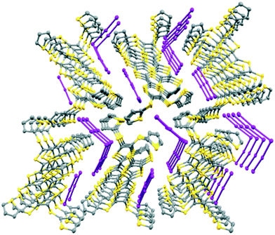 | ||
| Fig. 5 View down the a axis for (19A)2.I5.I3 showing the stacks of donor cation pairs separated by the pentaiodide and triiodide ions. Closest inter-stack contacts are between thiophenes. | ||
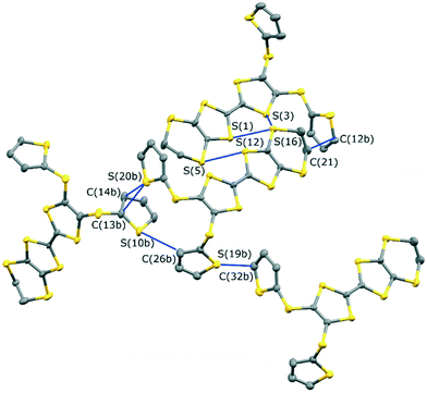 | ||
| Fig. 6 The network of intermolecular sulfur–carbon short contacts in (19A)2.I5.I3. Minor disordered components and hydrogen atoms are omitted for clarity. | ||
| Thiophene⋯thiophene | Thiophene⋯thiophene | ||
|---|---|---|---|
| S(19B)⋯C(31) | 3.29(6) | S(20B)⋯C(13) | 3.46(5) |
| S(19B)⋯(C32) | 3.26(7) | S(20B)⋯C(13B) | 3.38(6) |
| S(19B)⋯C(31B) | 3.50(9) | S(20B)⋯C(14B) | 3.43(6) |
| S(19B)⋯(C32B) | 3.34(6) | S(20B)⋯S(10) | 3.552(19) |
| Thiophene⋯ethylene bridge | |||
|---|---|---|---|
| C(11)⋯C(21) | 3.27(5) | ||
| C(12B)⋯C(21) | 3.51(5) | ||
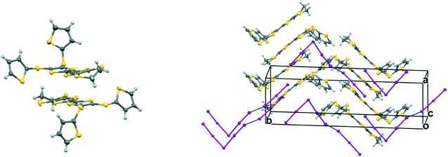
The second phase, 19A.I3, crystallises in the triclinic crystal system in space group P![[1 with combining macron]](https://www.rsc.org/images/entities/char_0031_0304.gif) with two donor radical cations and two triiodide anions in the asymmetric unit. Each of the radical cations is part of a centrosymmetric face-to-face pair. In one of these the centre of symmetry lies directly between the central double bonds of the two EDT-TTF systems, and there are close S⋯S contacts of 3.3038(15) and 3.4397(16) Å between the TTF units. In the second one the donor is slipped along its long axis by ca. 1.40 Å relative to the other and the centre lies between carbons at the termini of the central bonds (Fig. 7). The shortest contact between the TTF moieties is between these two carbon atoms (3.356(8) Å), while S⋯S contacts are longer since the TTF units are not opposite each other. The disposition of the thiophenes follows the pattern of one directed out to the side of the donor pair, and one up and away from it (torsion angles, S(TTF)–C(TTF)–S–C(thiophene): 7.6 and 67.0°, and 19.5 and 62.7°). The triiodide ions are isolated from one another and do not form a network, but both make two short contacts to sulfur atoms of a donor cation's dithiin ring (3.7130(12)–3.7628(12) Å), as has been observed in salts of other donors.20 The triiodide anions sandwich the donor cation pair both above and below and on either side with the long molecular axes for the donor and triiodide aligned, as shown in Fig. 7, and thus this complex has no promising pathways for electrical conduction.
with two donor radical cations and two triiodide anions in the asymmetric unit. Each of the radical cations is part of a centrosymmetric face-to-face pair. In one of these the centre of symmetry lies directly between the central double bonds of the two EDT-TTF systems, and there are close S⋯S contacts of 3.3038(15) and 3.4397(16) Å between the TTF units. In the second one the donor is slipped along its long axis by ca. 1.40 Å relative to the other and the centre lies between carbons at the termini of the central bonds (Fig. 7). The shortest contact between the TTF moieties is between these two carbon atoms (3.356(8) Å), while S⋯S contacts are longer since the TTF units are not opposite each other. The disposition of the thiophenes follows the pattern of one directed out to the side of the donor pair, and one up and away from it (torsion angles, S(TTF)–C(TTF)–S–C(thiophene): 7.6 and 67.0°, and 19.5 and 62.7°). The triiodide ions are isolated from one another and do not form a network, but both make two short contacts to sulfur atoms of a donor cation's dithiin ring (3.7130(12)–3.7628(12) Å), as has been observed in salts of other donors.20 The triiodide anions sandwich the donor cation pair both above and below and on either side with the long molecular axes for the donor and triiodide aligned, as shown in Fig. 7, and thus this complex has no promising pathways for electrical conduction.
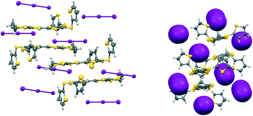 | ||
| Fig. 7 Crystal structure of 19A.I3 showing the orientations of the isolated triiodide ions (left) and how they isolate the radical cation donor pairs (right). | ||
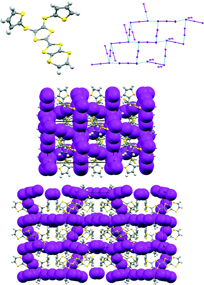
The iodine complex of donor 17A crystallises in the monoclinic space group C2/c with one donor monocation accompanied by two triiodides and three iodine molecules, all five of which lie on centres of symmetry. The crystal structure is composed of alternate layers perpendicular to the b axis, one of face-to-face donor radical cation pairs with their main axes lying at just 11° to the c axis, and the other a network of triiodide and iodine molecules (Fig. 8). The network is formed by lines of end-to-end triiodides which are bridged with iodine molecules to form rings containing twelve iodine atoms. However, there are also “crosslinks” between the I3−/I2 layers formed by further iodine molecules which cross the donor cation layers. As observed in other cases, one thiophene is displaced to the side of the door cation pair, and one directed up and away (torsion angles, S(TTF)–C(TTF)–S–C(thiophene): 7.5 and 72.8°). The former set of thiophene groups protrude through holes in the I3−/I2 layers. The iodine network contains lines of the two unique triiodides organised alternately, with I3−⋯I3− separations of 3.5560(19) Å, which are connected within the layer by two unique iodine molecules with I3−⋯I2 contacts of 3.394(2) or 3.5390(18) Å. The links between layers via a third iodine molecule have I3−⋯I2 contacts of 3.4010(19) Å. Within the radical cation pair one donor cation is displaced by ca. 1.35 Å along the main axis relative to the other with S⋯S contacts between TTF units of 3.351(7) and 3.486(7) Å. The layer structure precludes S⋯S contacts between different donor cation pairs.
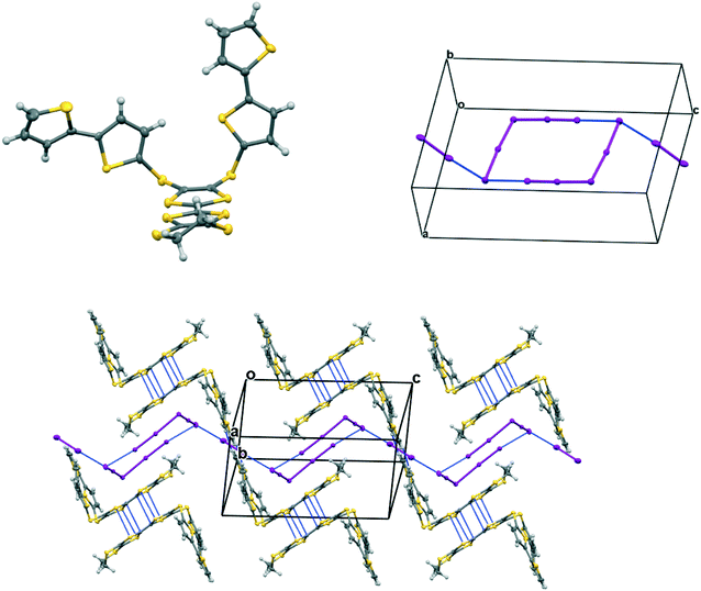
The complex formed by donor 19C, which contains two bithiophene side chains, by reaction with iodine has formula 19C.I5.0.5(I2) and crystallises in the triclinic space group P![[1 with combining macron]](https://www.rsc.org/images/entities/char_0031_0304.gif) . Donor cations are located in centrosymmetric face-to-face pairs with four S⋯S contacts between the TTF units of 3.369(4) and 3.394(4) Å. The donor cation pairs stack alternately with a (I5−)2 unit along the a + b direction, where the two pentaiodide anions form a centrosymmetric approximately oblong motif with two I5−⋯I5− contacts of 3.5713(9) Å, and angles of 87.66(2) and 88.29(3)° at the corners of the motif (Fig. 9). These dimeric units are linked to those in neighbouring stacks by iodine molecules located on centres of symmetry, with I5−⋯I2 contacts of 3.4236(11) Å. Some similar cyclic “I102−” units have been reported before but are closer to assemblies of triiodide and iodine.21 In contrast, tetramethylammonium pentaiodide form a network containing “squares” with twelve iodine atoms.22 Within the bithiophene units the thiophene rings are organised predominantly in trans mode with angles of 25.2 and 26.9° between the planes of the two rings, though one terminal ring has 72
. Donor cations are located in centrosymmetric face-to-face pairs with four S⋯S contacts between the TTF units of 3.369(4) and 3.394(4) Å. The donor cation pairs stack alternately with a (I5−)2 unit along the a + b direction, where the two pentaiodide anions form a centrosymmetric approximately oblong motif with two I5−⋯I5− contacts of 3.5713(9) Å, and angles of 87.66(2) and 88.29(3)° at the corners of the motif (Fig. 9). These dimeric units are linked to those in neighbouring stacks by iodine molecules located on centres of symmetry, with I5−⋯I2 contacts of 3.4236(11) Å. Some similar cyclic “I102−” units have been reported before but are closer to assemblies of triiodide and iodine.21 In contrast, tetramethylammonium pentaiodide form a network containing “squares” with twelve iodine atoms.22 Within the bithiophene units the thiophene rings are organised predominantly in trans mode with angles of 25.2 and 26.9° between the planes of the two rings, though one terminal ring has 72![[thin space (1/6-em)]](https://www.rsc.org/images/entities/char_2009.gif) :
:![[thin space (1/6-em)]](https://www.rsc.org/images/entities/char_2009.gif) 28 trans
28 trans![[thin space (1/6-em)]](https://www.rsc.org/images/entities/char_2009.gif) :
:![[thin space (1/6-em)]](https://www.rsc.org/images/entities/char_2009.gif) cis rotational disorder. Donor cation pairs are aligned side-by-side along the b axis but there are no short S⋯S contacts between the EDT-TTF donor edges (shortest 3.994(4) Å). However, there is a short S⋯C contact (3.47(3) and 3.48(7) Å for major and minor disordered components respectively) between thiophene rings of bithiophene groups attached to donors related by a translation along the a axis (Fig. 10). In common with the other five salts, this material was also an insulator at room temperature.
cis rotational disorder. Donor cation pairs are aligned side-by-side along the b axis but there are no short S⋯S contacts between the EDT-TTF donor edges (shortest 3.994(4) Å). However, there is a short S⋯C contact (3.47(3) and 3.48(7) Å for major and minor disordered components respectively) between thiophene rings of bithiophene groups attached to donors related by a translation along the a axis (Fig. 10). In common with the other five salts, this material was also an insulator at room temperature.
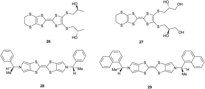
A considerable number of radical cation salts of organosulfur donors with polyiodide anions are known, prepared either by chemical oxidation with diffused iodine or by electrocrystallisation with tetrabutylammonium triiodide. However, design of salts is complicated because of the diversity of different polyiodide ions, I3−, I5−, I7− which can be formed, though I3− is most common. Further variables are inclusion of additional iodine molecules or solvents and the different valence states for the donors. BEDT-TTF 2, for example, forms at least seven different phases with iodine, usually several in the same experiment.23 Three of these contain layers of triiodides which lie between blocks of tightly packed donors, and interface with their ethylene bridges, with different electrical properties depending on the dispositions of the triiodides. In a further phase triiodides lie among the donors parallel to the donors' main axes, and additional iodine molecules are included in another phase. Two further phases have sheets of ET/triiodide separated by sheets of I5− or I82−. It is thus particularly difficult to control or predict the formation of radical cation salts prepared with iodine, even with a compact donor with limited conformational freedom like BEDT-TTF. For less symmetrical donors there appears to be a strong tendency for the triiodides to lie side by side with donors which breaks up the S⋯S contacts needed for conductivity as in the salts with chiral donors 26–27 (Scheme 4).20,24 In the former case, three different phases are formed, but only one is semiconducting. In the case of the chiral bis(pyrrolo)TTFs 28–29 (Scheme 4), the neutral donors form chiral stacks related by 43 or near 43 axes, but their triiodide salts forego this packing arrangement entirely, preferring to align triiodide ions side by side with donors.25 The shortest S⋯I contacts lie in the range 3.58–3.70 Å.
Shao has reported details of polyiodide complexes of donors 22–23 (Scheme 3), analogous to 15A and 15B, in which the four thiophenes are replaced by 4-fluorophenyl and 3-fluorophenyl groups respectively. The former forms a 22.I3.I2 complex and the latter forms a salt of the donor dication of 23 with a polymeric polyiodide chain crosslinked with iodine molecules.18 Related donors 24 and 25 with four 3-methylphenyl or 4-methoxyphenyl groups (Scheme 3) also form salts of their dications accompanied by networks composed of triiodide anions and iodine molecules.19 This illustrates how difficult it is to predict which polyiodide complex will form, especially bearing in mind, as Shao points out, that the dication 23 has formed from the least readily oxidized donor among compounds 21–25 according to cyclic voltammetry measurements. Crystal packing forces control the product formed, but there are numerous combinations to consider. The donor cations in 22.I3.I2 are paired just as in the pentaiodide salts of 15A and 15B with two 4-fluorophenyl groups wrapping around each end of the donor pair. The triiodide and iodine species form an almost identical network to those in 15A.I5 and 15B.I5 with fused six and sixteen membered rings, with closest I⋯I contacts between the I3− and I2 species of 3.33 and 3.36 Å, slightly longer than in the networks from 15A and 15B where we chose to consider these to be I5− anions. We assigned all our six salts to contain the monocations of donors, primarily to balance the charges on the polyiodide anions. The length of the central double bond in the TTF unit is sensitive to the charge, varying from 1.34 to 1.39 to 1.42 Å as the charge increase from zero to +1 to +2, though this is difficult to determine accurately in the presence of several iodine atoms, but they lie in range 1.35(2)–1.40(3) Å. The infra-red spectra of the salts also contain a common stretch in the range 1324–1331 cm−1. In summary, iodine may be an easy oxidant to use, but it is difficult to control the products produced. Furthermore, small changes in conditions may produce other phases. Design is much more feasible with larger organic-type acceptors, with only the stoichiometry and solvent inclusion as variables.
Conclusions
A series of TTF donors carrying two or four thiophene, bithiophene or terthiophene substituents have been synthesized, and their first crystalline radical cation salts prepared by reaction with iodine. These all contain face-to-face pairs of monocation donors. In the pentaiodide salts with donors containing four thiophenes, 15A and 15B, the thiophene side chains wrap around each other, enabled by a mutual shift along the main axis of the donors. Where there are just two substituents the TTF units are nearly directly opposed, and side chains are projected away from the donor pair, one to the side and one above. Solubility becomes an issue for those donors containing terthiophenes, and further substitutions will be needed to provide more applicable materials. Nevertheless, cyclic voltammetry shows that for donor 19E a third oxidation process associated with the terthiophene is observed just above the typical TTF processes. The polyiodide salt of donor 19C which contains bithiophenes shows contacts between bithiophene rings, and such interactions could become important in electroactive materials with this combination of TTF and polythiophene groups. Four of the crystal structures contain pentaiodide ions, which may also be considered as a I3⋯I2 unit, and they show some variability in their geometries with their I–I–Î⋯I–I angle lying between 80.8 and 97.3° and the longest I–I bond lying in the range 3.176–3.256 Å.Experimental
Full details of experimental procedures are given in the ESI.† Crystal structure data has been deposited at the Cambridge Crystallographic Data Centre, with numbers as in Table 2.Conflicts of interest
None to report.Acknowledgements
LM and TJB would like to thank the Royal Society and Leverhulme Trust for financial support (LT170022 and RPG-2019-242). OS thanks Tübitak for an International Postdoctoral Research Fellowship and Nottingham Trent University for further support.References
- D. Canevet, M. Sallé, G. Zhang, D. Zhang and D. Zhu, Chem. Commun., 2009, 2245–2269 Search PubMed; TTF Chemistry: Fundamentals and Applications of Tetrathiafulvalenes, ed. J.-I. Yamada and T. Sugimoto, Springer, Berlin, 2004 Search PubMed.
- T. P. Kaloni, P. K. Giesbrecht, G. Schreckenbach and M. S. Freund, Chem. Mater., 2017, 29, 10248–10283 Search PubMed.
- L. Martin, Coord. Chem. Rev., 2018, 376, 277–291 Search PubMed; J.-P. Griffiths and J. D. Wallis, J. Mater. Chem., 2005, 15, 347–365 Search PubMed.
- C. Rovira, J. Veciana, E. Ribera, J. Tarres, E. Canadell, R. Rousseau, M. Mas, E. Molins, M. Almeida, R. T. Henriques, J. Morgado, J.-P. Schoeffel and J.-P. Pourget, Angew. Chem., Int. Ed. Engl., 1997, 36, 2324–2326 Search PubMed; R. A. L. Silva, I. C. Santos, E. B. Lopes, S. Rabaca, J. Vial-Gancedo, C. Rovira, M. Almeida and D. Belo, Cryst. Growth Des., 2016, 16, 3924–3931 Search PubMed; R. Pfattner, M. Mas-Torrent, I. Billoti, A. Brilliante, S. Milita, F. Liscio, T. Marszalek, J. Ulanski, A. Nosal, M. Leufgen, G. Schmidt, L. W. Molenkamp, V. Laukhin, J. Veciana and C. Rovira, Adv. Mater., 2010, 22, 4198–4203 Search PubMed.
- R. A. L. Silva, I. C. Santos, J. Wright, J. T. Coutinho, L. C. Pereira, E. B. Lopes, S. Rabaca, J. Vial-Gancedo, C. Rovira and M. Almeida, Inorg. Chem., 2015, 54, 7000–7006 Search PubMed; R. A. L. Silva, A. I. Neves, M. L. Afonso, I. C. Santos, E. B. Lopes, F. Del Pozo, R. Pfattner, M. Mas-Torrent, C. Rovira, M. Almeida and D. Belo, Eur. J. Inorg. Chem., 2013, 2440–2446 Search PubMed.
- R. Berridge, I. M. Serebryakov, P. J. Skabara, E. Orti, R. Viruela, R. Pou-Amerigo, S. J. Coles and M. B. Hursthouse, J. Mater. Chem., 2004, 14, 2822–2830 Search PubMed.
- A. L. Kanibolotsky, N. J. Findlay and P. J. Skabara, Beilstein J. Org. Chem., 2015, 11, 1749–1766 Search PubMed; A. L. Kanibolotsky, L. Kanibolotskaya, S. Gordeyev, P. J. Skabara, I. McCulloch, R. Berridge, J. E. Lohr, F. Marchioni and F. Wudl, Org. Lett., 2007, 9, 1601–1604 Search PubMed; P. J. Skabara, D. M. Roberts, I. M. Serebyakov and C. Pozo-Gonzalo, Chem. Commun., 2000, 1005–1006 Search PubMed.
- I. A. Wright, N. J. Findlay, S. Arumugam, A. R. Inigo, A. L. Kanibolotsky, P. Zassowski, W. Domagala and P. J. Skabara, J. Mater. Chem. C, 2014, 2, 2674–2683 Search PubMed; I. A. Wright, P. J. Skabara, J. C. Forgie, A. L. Kanibolotsky, B. Gonzalez, S. J. Coles, S. Gambino and I. D. W. Samuel, J. Mater. Chem., 2011, 21, 1462–1469 Search PubMed.
- Q. Wang, J. D. Wallis, Y. Wu and M. Pilkington, CrystEngComm, 2014, 16, 10235–10244 Search PubMed; R. J. Brown, A. C. Brooks, J.-P. Griffiths, B. Vital, P. Day and J. D. Wallis, Org. Biomol. Chem., 2007, 5, 3172–3182 Search PubMed.
- T. Kakinuma, H. Kojima, T. Kawamoto and T. Mori, J. Mater. Chem. C, 2013, 1, 2900–2905 Search PubMed; T. Abbaz, A.-K. Gouasmia, H. Fujiwara, T. Hiraoka, T. Sugimoto, M. Taillefer and J.-M. Fabre, Synth. Met., 2007, 157, 508–516 Search PubMed.
- J. Sun, X. Lu, J. Shao, Z. Cui, Y. Shao, G. Jiang, W. Yu and X. Shao, RSC Adv., 2013, 3, 10193–10196 Search PubMed; J. Sun, X. Lu, J. Shao, Z. Cui, X. Li, S. Zhang, B. Wang, J. Zhao, B. Wang, J. Zhao, Y. Shao, R. Fang, Z. Wang, W. Yu and X. Shao, Chem. – Eur. J., 2013, 19, 12517–12525 Search PubMed.
- S. Zhang, X. Lu, J. Sun, Y. Zhao and X. Shao, CrystEngComm, 2015, 17, 4110–4116 Search PubMed.
- Q. Meng, J. Gao, R. Li, L. Jiang, C. Wang, H. Zhao, C. Liu, H. Li and W. Hu, J. Mater. Chem., 2009, 19, 1477–1482 Search PubMed.
- M. Funahashi and J.-I. Hanna, Adv. Mater., 2005, 17, 594–598 Search PubMed.
- T. Nakamura, S. Iwasaka, H. Nakano, K. Inoue, T. Nogami and H. Mikawa, Bull. Chem. Soc. Jpn., 1987, 60, 365–368 Search PubMed; J. Garin, R. Andreu, J. Orduna and J. Royo, Synth. Met., 2001, 120, 749–750 Search PubMed.
- M. Savastano, A. Martinez-Camerena, C. Bazzicalupi, E. Delgado-Pinar, J. M. Llinares, P. Mariani, B. Verdejo, E. Garcia-Espana and A. Bianchi, Inorganics, 2019, 7, 48 Search PubMed; M. Otsuka, H. Mori, H. Kikuchi and K. Takano, Comput. Theor. Chem., 2011, 973, 69–75 Search PubMed; P. H. Svensson and L. Kloo, Chem. Rev., 2003, 103, 1649–1684 Search PubMed; A. J. Blake, W.-S. Li, V. Lippolis, M. Schröder, F. A. Devillanova, R. O. Gould, S. Parsons and C. Radek, Chem. Soc. Rev., 1998, 27, 195–206 Search PubMed.
- M. Savastano, C. Bazzicalupi, C. Garcia, C. Gellini, M. D. Lopez de la Torre, P. Mariani, F. Pichierri, A. Bianchi and M. Melguizo, Dalton Trans., 2017, 46, 4518–4529 Search PubMed; M. Savastano, C. Bazzicalupi, C. Giorgi, C. Garcia-Gallarin, M. D. Lopez de la Torre, F. Pichierri, A. Bianchi and M. Melguizo, Inorg. Chem., 2016, 55, 8013–8024 Search PubMed.
- L. Ma, H. Peng, X. Lu, L. Liu and X. Shao, RSC Adv., 2018, 8, 17321–177324 Search PubMed.
- L. Ma, H. Peng, X. Lu, L. Liu and X. Shao, Chin. J. Chem., 2018, 36, 845–850 Search PubMed.
- L. Martin, J. D. Wallis, M. Guziak, P. Maksymiw, F. Konalian-Kempf, A. Christian, S.-I. Nakatsuji, J.-I. Yamada and H. Akutsu, Dalton Trans., 2017, 46, 4225–4234 Search PubMed.
- G. J. Reiss, Z. Kristallogr. - Cryst. Mater., 2019, 234, 737–739 Search PubMed; C. Wieczorrek, Acta Crystallogr., Sect. C: Struct. Chem., 2000, 56, 1082–1084 Search PubMed.
- C. A. L. Filgueiras, A. Horn Jr., J. M. S. Skakle and J. L. Wardell, Acta Crystallogr., Sect. E: Crystallogr. Commun., 2001, 57, o338–o340 Search PubMed.
- H. Kobayashi, K. Kawano, T. Naito and A. Kobayashi, J. Mater. Chem., 1995, 5, 1681–1687 Search PubMed; M. A. Beño, U. Geiser, K. L. Kostka, H. H. Wang, K. S. Webb, M. A. Firestone, K. D. Carlson, L. Nuñez, M.-H. Whangbo and J. M. Williams, Inorg. Chem., 1987, 26, 1912–1920 Search PubMed; V. F. Kaminskii, V. N. Laukhin, V. A. Merzhanov, O. Ya. Neiland, V. Yu. Khodorkovskii, R. P. Shibaeva and E. B. Yagubskii, Izv. Akad. Nauk SSSR, Ser. Khim., 1986, 342–347 Search PubMed; J. M. Williams, T. J. Emge, H. Wang, M. A. Beño, P. T. Copps, L. N. Hall, K. D. Carlson and G. W. Crabtree, Inorg. Chem., 1984, 23, 2558–2560 Search PubMed; P. C. W. Leung, T. J. Emge, M. A. Beno, H. H. Wang, J. M. Williams, V. Petricek and P. Coppens, J. Am. Chem. Soc., 1984, 106, 7644–7646 Search PubMed; V. F. Kaminskii, T. G. Prokorova, R. P. Shibaeva and E. B. Yagubskii, JETP Lett., 1984, 39, 17–19 Search PubMed.
- I. Awheda, S. J. Krivickas, S. Yang, L. Martin, M. A. Guziak, A. C. Brooks, F. Pelletier, M. Le Kerneau, P. Day, P. Horton, H. Akutsu and J. D. Wallis, Tetrahedron, 2013, 69, 8738–8750 Search PubMed.
- L. Martin, S. Yang, A. C. Brooks, P. N. Horton, L. Male, O. Moulfi, L. Harmand, P. Day, W. Clegg, R. W. Harrington and J. D. Wallis, CrystEngComm, 2015, 17, 7354–7362 Search PubMed.
Footnote |
| † Electronic supplementary information (ESI) available. CCDC 2011618–2011623. For ESI and crystallographic data in CIF or other electronic format see DOI: 10.1039/d0ce00954g |
| This journal is © The Royal Society of Chemistry 2020 |

