Synthesis of novel mesoporous sulfated zirconia nanosheets derived from Zr-based metal–organic frameworks†
Ningyue
Lu
a,
Xuelian
Zhang
a,
Xiaoliang
Yan
 a,
Dahai
Pan
a,
Binbin
Fan
a,
Dahai
Pan
a,
Binbin
Fan
 *a and
Ruifeng
Li
*ab
aCollege of Chemistry and Chemical Engineering, Taiyuan University of Technology, Taiyuan 030024, China. E-mail: fanbinbin@tyut.edu.cn; rfli@tyut.edu.cn; Fax: +86 351 6010121; Tel: +86 351 6018384
bKey Laboratory of Coal Science and Technology MOE, Taiyuan University of Technology, Taiyuan 030024, P.R. China
First published on 28th October 2019
Abstract
Flower-like mesoporous sulfated zirconia nanosheets (SZNs) were developed by thermal decomposition of in situ sulfated Zr-MOFs for the first time. The sulfated Zr-MOFs act as both a morphological template and zirconium and sulfate sources. The amounts of SO42− in the synthesis system of UiO-66 greatly affected the morphology of sulfated Zr-MOFs via a coordination modulation method. The flower-like sulfated Zr-MOF nanosheets were obtained as the S/Zr ratio increased to 0.5. The calcination temperature has a great influence on the structural properties and catalytic performances of sulfated zirconia nanosheets other than morphology. Sulfated zirconia nanosheets (SZN-500) obtained by calcination at 500 °C had a large surface area (186.1 m2 g−1) and strong bonding between sulfate and zirconia atoms and exhibited a good catalytic activity and reusability for the transesterification of tributyrin with methanol. This viable synthetic strategy can offer an alternative way to prepare functionalized metallic oxides with a specific morphology.
Introduction
Sulfated zirconia (SZ) with strong or superacidic characteristics is one of the most widely studied solid acid catalysts and exhibits excellent catalytic activity for many important reactions, such as alkylation, hydrocarbon isomerization, condensation, acylation, nitration, oligomerization, esterification, transesterification, etc.1–3 However, SZ materials prepared by the conventional method, that is, post-sulfonation of Zr hydroxide obtained by precipitation and calcination, usually suffer from poor porosity and low surface areas, which cause heavy diffusion limitation for reactants/products, especially in reactions involving bulky reactants, and thus decrease the catalytic activity of SZ materials. Therefore, a variety of methods for the preparation of SZ materials with mesoporous structures and high surface areas have been proposed.4,5 These methods can be mainly divided into two types. SZ materials with mesoporous structures can be synthesized via introducing various pore-forming agents into the synthesis system of Zr hydroxide or modifying the synthesis parameters in the sol–gel process.6–8 Although these methods can synthesize SZ materials with mesoporous structures, they cannot effectively synthesize SZ materials with high surface areas and tailored morphologies. For heterogeneous catalytic reactions, apart from the porosity, the morphology of the catalyst also is an important factor that influences their catalytic performances. For example, SAPO-34 catalysts with a plate-like morphology exhibited better catalytic activity, selectivity and lifetimes in MTO (methanol to olefins) reactions by enhancing the accessibility of acid sites and promoting the diffusion of the reactants/products.9 MFI zeolite nanosheets showed high propylene selectivity and long catalytic lifetimes in the MTP (methanol to propylene) reaction due to their excellent diffusivity.10,11 However, studies on the morphologies of SZ materials have rarely been reported. Hence, a novel synthesis strategy to prepare SZ materials with mesoporous structures, high surface areas and tailored morphologies is highly desired.Metal–organic frameworks (MOFs) are potentially microporous materials due to their ordered crystalline structures, high surface areas, various structural topologies and tunable chemical properties.12–23 Recently, MOFs have proved to be versatile templates and precursors for the preparation of nanoporous carbons (NPCs), metal oxides and other nanomaterials via thermal decomposition processes.24–27 There is no doubt that these derived-nanomaterials can inherit the morphology of their pristine parent and display multiple morphologies via controlling the morphology of MOFs.28,29 UiO-66, a class of Zr-MOFs, has been widely used as a sacrificial template to prepare zirconia. Zirconia with a mesoporous structure and large surface area can be formed by removing the organic species in the thermal decomposition of Zr-MOFs. Moreover, the morphology of the Zr-MOFs can be facilely tuned by a coordination modulation method; thus, the specific morphology of zirconia can be fabricated by deriving from the Zr-MOFs. Our previous studies have shown that mesoporous tetragonal zirconia (t-ZrO2) with a large surface area and octahedral morphology can be obtained with UiO-66 as both a zirconium source and a morphological template.30 Thus, the characteristics of metal oxides derived from MOFs give inspiration to design mesoporous SZ materials with high surface areas and tailored morphologies.
In this paper, we synthesized flower-like mesoporous sulfated zirconia nanosheets (SZNs) with high BET surface areas by thermal decomposition of in situ synthesized sulfated Zr-based MOFs (Zr-MOFs-S) for the first time. The textural structures and acidic properties of SZN materials were further investigated, and the corresponding catalytic performances in the transesterification of tributyrin with methanol were also studied.
Experimental
Sample preparation
Characterization
The XRD patterns were recorded on a Shimadzu XRD-6000 diffractometer with Cu Kα radiation. Morphologies, energy dispersive spectroscopy (EDS) and elemental mapping for crystals were performed using an S-4800 Hitachi scanning electron microscope. Transmission electron microscopy (TEM) and selected area electron diffraction (SAED) were conducted with a JEOL JEM-2100 microscope. The samples were dispersed in ethanol and deposited on a copper grid covered with holey carbon. Nitrogen adsorption/desorption isotherms were measured at −196 °C on a Quantachrome Autosorb analyzer. Before the analysis, the sample was evacuated at 300 °C for 3 h. The total surface area was obtained from the BET equation. Pore size distribution was calculated by using the density functional theory (DFT) method. The pore volume was estimated at a relative pressure of 0.99. The Fourier transform infrared (FT-IR) spectra of framework vibrations of samples in the form of KBr pellets were recorded at room temperature using a Shimadzu IRAffinity-1 spectrometer. Infrared spectra of pyridine-adsorbed samples were collected on the Shimadzu IRAffinity-1 spectrometer equipped with a vacuum cell. Prior to the test, the samples were activated in a vacuum line at 400 °C for 4 h. Temperature programmed desorption of ammonia (NH3-TPD) measurements were performed using an AutoChem 2720 instrument with He as a carrier gas (30 mL min−1). Before the measurements, the sample was activated at 300 °C for 3 h in a He atmosphere. Thermogravimetric analysis (TGA) was performed under an air atmosphere (50 mL min−1) using a NETZSCH STA 449 F3 instrument. Atomic force microscopy (AFM) was carried out on an SPA-300 HV atomic force microscope.Catalytic test
The transesterification of tributyrin with methanol was conducted in a Teflon-lined stainless steel autoclave. 0.1 g of catalyst, 52 mmol of methanol (1.67 g) and 1.3 mmol of tributyrin (0.4 g) were added into the reactor, and then the mixture was magnetically stirred at 800 rpm at the designated temperature for 6 h. After the reaction, the product was analyzed on an Agilent 7820B gas chromatograph equipped with an HP-1 capillary column and a FID, and chlorobenzene was used as the internal standard. In the cycle tests, the used catalyst was recovered by centrifugation, washed with methanol, dried and then used for the subsequent reaction.Results and discussion
Characterization of Zr-MOFs-S
Zr-MOFs-S was prepared on the basis of the synthesis of UiO-66. Fig. S1† shows the XRD patterns of the Zr-MOFs-S samples synthesized at different S/Zr molar ratios. As shown in Fig. S1,† the introduction of (NH4)2SO4 into the conventional synthesis system of UiO-66 greatly influenced the crystallization of the UiO-66 material. In comparison with the UiO-66 sample synthesized in the absence of (NH4)2SO4 (Fig. S2†), the intensities of the characteristic diffraction peaks of the Zr-MOFs-S samples decreased sharply with the increase of the S/Zr molar ratio. Moreover, a broad peak at 2θ = 29.4° appeared as the S/Zr molar ratio increased to 0.3, indicating partial amorphization. The results showed that the addition of (NH4)2SO4 in the UiO-66 synthesis system interferes with the nucleation and crystallization of UiO-66. As the S/Zr ratio increased to 0.5, the obtained Zr-MOFs-S-0.5 sample displayed a very weak and broad diffraction peak attributed to UiO-66 in the XRD pattern at around 2θ = 7.4°, demonstrating that the Zr-MOFs-S synthesized at a high S/Zr molar ratio was nearly amorphous. The amorphization of the Zr-MOFs-S samples may be due to the decrease of the organic linkers coordinated with Zr as the S/Zr ratio increases. The amount of organic linkers can be further estimated by thermogravimetric analysis measurements.The TGA curves of the different Zr-MOFs-S samples are presented in Fig. S3.† All the Zr-MOFs-S samples exhibited a nearly continuous weight loss up to 450 °C and complete framework decomposition at 450–600 °C. The first weight loss step before 450 °C is assigned to the evaporation of adsorbed water and the trapped solvent molecules inside the framework. The second step of weight loss represents the decomposition of organic linkers. The composition of the perfect UiO-66 is Zr6O6(C8H4O4)6, and the organic linker to Zr molar ratio should be equal to 1 theoretically. If the Zr/organic linker ratio is larger than 1, it shows that either the sample is defective or the organic linkers are replaced by other indecomposable molecules.32 The weight losses of Zr-MOFs-S-0.1, Zr-MOFs-S-0.3 and Zr-MOFs-S-0.5 were 30.6, 19.8, and 16.5%, respectively. Based on the calculating method and TGA results, the Zr/organic linker molar ratios for Zr-MOFs-S-0.1, Zr-MOFs-S-0.3 and Zr-MOFs-S-0.5 were 1.7, 3.7, and 4.8, respectively.33 These results further confirmed that the amount of organic linkers coordinated with Zr decreased in the Zr-MOFs-S samples as the S/Zr ratio increased.
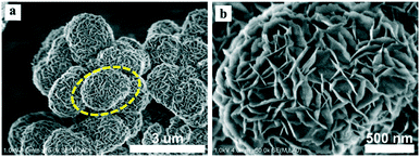
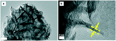
The morphologies of the different Zr-MOFs-S samples were examined with SEM. It can be seen that the Zr-MOFs-S samples synthesized at the different S/Zr ratios exhibited different morphologies (Fig. S4†). Different from the pristine octahedral UiO-66, Zr-MOFs-S-0.1 showed a glossy spherical morphology, indicating that a little amount of (NH4)2SO4 in the UiO-66 synthesis systems can greatly change the morphology of the synthesized Zr-MOFs. As the S/Zr molar ratio further increased, the surface of the synthesized Zr-MOFs-S spherical crystals became rough gradually. When the S/Zr molar ratio increased to 0.5, a flower-like morphology assembled from nanosheets was observed (Fig. 1). The thickness of the nanosheets is about 5 nm. This can be further confirmed by the TEM images of Zr-MOFs-S-0.5. As shown in Fig. 2, Zr-MOFs-S-0.5 clearly demonstrated the flower-like morphology assembled from nanosheets with a thickness of ca. 5 nm at a higher magnification. These results revealed that the morphologies of the Zr-MOFs-S samples can be facilely tailored as a function of (NH4)2SO4 amount, and nanosheet crystals were formed at high (NH4)2SO4 amounts.
In order to reveal the role of (NH4)2SO4 on the morphologies of the Zr-MOFs-S samples, an equivalent amount of H2SO4 as a SO42− source or NH4Cl and NH4NO3 as an NH4+ source was added to the synthesis system of UiO-66 instead of (NH4)2SO4. As shown in Fig. S5,† Zr-MOFs-NH formed octahedral agglomerates, which was analogous to the pristine UiO-66. However, Zr-MOFs-SH showed a flower-like morphology similar to Zr-MOFs-S-0.5. These results demonstrated that SO42− anions play a crucial role in the formation of nanosheets rather than the types of cations and pH value. Moreover, for the purpose of further demonstrating the unique role of SO42−, NH4NO3 containing O negative ions was used to replace (NH4)2SO4 in the synthesis system, and the synthesized Zr-MOFs-NO showed spherical agglomerates. It is well-known that the formation of UiO-66 is based on the coordination of Zr4+ ions with BDC linkers. The crystal size and morphology of UiO-66 can be deliberately controlled through a coordination modulation process, in which modulators, such as acetic acid, benzoic acid, hydrofluoric acid, etc., are utilized to directly affect the coordination equilibria.34–37 In the present work, the nanosheet crystal growth of Zr-MOFs-S is presumably explained by the oriented attachment mechanism.38 In the synthesis system in the absence of SO42−, the Zr4+/hydroxo clusters react with the deprotonated BDC2− organic ligands (Zr–BDC) to generate UiO-66 crystals with an octahedral morphology predominately. However, in the synthesis system in the presence of SO42−, the SO42− ions would compete with the BDC linkers to coordinate with the Zr clusters, thus, disturbing the Zr–BDC reaction and inhibiting the crystal growth in the direction of UiO-66 frameworks. With the increase of the SO42− ions, the competition between SO42− and BDC2− is further aggravated, which results in the lower crystallinity of the UiO-66 structure and flower-like aggregates with nanosheets.
Physical characterization of the sulfated zirconia nanosheets
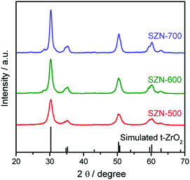
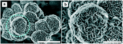
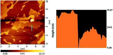
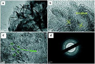
The sulfated zirconia (SZ) samples were prepared by the thermal decomposition of the Zr-MOFs-S-0.5 sample at different temperatures. It is well-known that the calcination temperature is one of the most crucial parameters affecting the structural properties of sulfated zirconia.1,39Fig. 3 shows the XRD patterns of the different SZ samples obtained at different calcination temperatures. As shown in Fig. 3, the characteristic diffraction peaks of Zr-MOFs-S disappeared completely and new diffraction peaks ascribed to the tetragonal phase of ZrO2 (t-ZrO2) were clearly observed in the XRD patterns of the SZ samples (JCPDS card No. 88-1007). With the increase of calcination temperature, the monoclinic phase was detected for SZ prepared at 700 °C.The SEM images of the different SZ samples are shown in Fig. 4 and S6.† All the samples inherited the morphology of the Zr-MOFs-S-0.5 precursor and showed flower-like nanosheet agglomerates regardless of the calcination temperature. The AFM images show that the thickness of the nanosheets was 4.81 nm (Fig. 5). Sulfated zirconia nanosheets (SZNs) can be further confirmed by the TEM images (Fig. 6). Fig. 6b shows the high-resolution TEM image of the nanoparticles. The lattice spacing was 0.295 nm corresponding to the (011) crystal face of t-ZrO2. For the SZN-500 sample, the existence of highly dispersed ZrO2 nanoparticles and the formation of channels between these nanoparticles could also be clearly observed from the enlarged TEM image shown in Fig. 6c. Moreover, SAED analysis of the nanoparticles in Fig. 6d showed a ring-like diffraction pattern with dispersed bright spots, which were attributed to the existence of the tetragonal phase of ZrO2.40,41 In order to give consideration to the dispersity of S species, elemental mapping was conducted for SZN-500 and is shown in Fig. 7. It can be clearly seen that the Zr, O and S elements were uniformly dispersed throughout the framework of the SZN-500 sample, showing that the S species were successfully introduced and highly dispersed on the skeleton of sulfated zirconia.
Fig. 8 shows the N2 adsorption–desorption isotherms and the corresponding pore size distribution curves of the different SZN samples. All the N2 adsorption–desorption isotherms of the SZN samples were typical type IV isotherms with hysteresis loops, due to the capillary condensation associated with mesopores, and the mesoporosity may be assigned to the aggregation of nanoparticles with each other. For SZN-500, its pore size distribution was narrow and gave a mean value at 5.2 nm (inset), whereas the pore size distributions of SZN-600 and SZN-700 became broader. This may be caused by the different aggregation extent of the SZ nanoparticles in the SZN samples obtained at the different calcination temperatures. Inspiringly, the BET surface area and external area of SZN-500 were 186.1 m2 g−1 and 135.9 m2 g−1, respectively, which was difficult to achieve by the conventional preparation method (Table 1). The BET surface areas and external areas of the SZN samples also were related to the calcination temperatures. With the increase of calcination temperature, the BET surface areas of the SZN samples decreased. These results indicated that it is feasible to prepare sulfated zirconia nanosheets (SZNs) with mesoporous structures and a higher surface area via thermal decomposition of in situ synthesized sulfated Zr-MOFs.
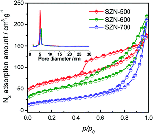 | ||
| Fig. 8 N2 adsorption–desorption isotherms and pore distribution plots (inset) of the different SZN samples. | ||
| Samples | Sulfur contenta (wt%) | S BET (m2 g−1) | S ext (m2 g−1) | S mic (m2 g−1) | V pore (cm3 g−1) | D pore (nm) |
|---|---|---|---|---|---|---|
| a Determined by EDS. b Determined by N2 adsorption. | ||||||
| SZN-500 | 3.8 | 186.2 | 135.9 | 50.3 | 0.25 | 5.3 |
| SZN-600 | 1.8 | 151.7 | 119.9 | 31.8 | 0.31 | 8.7 |
| SZN-700 | 1.0 | 79.3 | 71.2 | 8.1 | 0.33 | 16.5 |
| SZ-r | 3.6 | 126.7 | 82.3 | 44.4 | 0.12 | 3.9 |
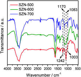
The states of the S species in the SZN samples were checked by FTIR measurements. As shown in Fig. 9, all the SZN samples displayed bands at 1242 cm−1, 1170 cm−1, 1083 cm−1 and 1003 cm−1, which are ascribed to asymmetric and symmetric stretching frequencies of S![[double bond, length as m-dash]](https://www.rsc.org/images/entities/char_e001.gif) O and S–O bonds. It is well acknowledged that, for SZ materials, the bands attributed to inorganic chelating bidentate sulfate ions coordinated to metal cations generally appear at about 1202 cm−1, 1123 cm−1, 1043 cm−1 and 983 cm−1.42 Thus, the sulfate vibration bands in the SZ samples shifted toward higher wavenumbers, indicative of the formation of strong bonding between sulfates and zirconia atoms in the SZN samples.43 With the increase of calcination temperature, the intensity of the bands at 1242 cm−1 and 1083 cm−1 decreased in the FTIR spectra of the SZN samples. This is due to the little amounts of SO42− species in these samples, which is consistent with the results of EDS analysis (Table 1).
O and S–O bonds. It is well acknowledged that, for SZ materials, the bands attributed to inorganic chelating bidentate sulfate ions coordinated to metal cations generally appear at about 1202 cm−1, 1123 cm−1, 1043 cm−1 and 983 cm−1.42 Thus, the sulfate vibration bands in the SZ samples shifted toward higher wavenumbers, indicative of the formation of strong bonding between sulfates and zirconia atoms in the SZN samples.43 With the increase of calcination temperature, the intensity of the bands at 1242 cm−1 and 1083 cm−1 decreased in the FTIR spectra of the SZN samples. This is due to the little amounts of SO42− species in these samples, which is consistent with the results of EDS analysis (Table 1).
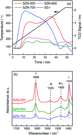
The acidic properties of the prepared SZN samples were investigated by NH3-TPD and pyridine-IR spectroscopy. The NH3-TPD profiles over the different SZN samples are illustrated in Fig. 10(a). The SZN-500 sample showed weak, medium and strong acidity at the temperature region of 170–550 °C, while SZN-600 and SZN-700 just possessed weak and medium acid sites, and the amount of total acid sites decreased with the increase of the calcination temperature, indicating that the calcination temperature is also an important factor influencing the acidic properties of the SZN samples. In addition, The SZ-r sample prepared by post-sulfonation of UiO-66 with (NH4)2SO4 and then calcination at 500 °C showed more weak acid sites, less strong acid sites and a similar total acid site amount in comparison to the SZN-500 sample. The Brønsted and Lewis acidic sites of the SZN samples were distinguished in the pyridine-IR spectra. From Fig. 10(b), the two bands at 1445 and 1606 cm−1, the diagnostic bands for the existence of Lewis acid sites, could be clearly observed in the pyridine-IR spectra of the SZN samples.44 In contrast, the band at 1535 cm−1, attributed to Brønsted acidic sites, was very weak. The results indicated that the acid sites on the SZN samples were mainly Lewis acidic sites, and a logical surface structural model was proposed (Scheme 1).
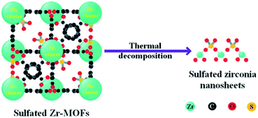 | ||
| Scheme 1 Proposed structural transformation model of sulfated Zr-MOFs into sulfated zirconia nanosheets. | ||
Catalytic studies
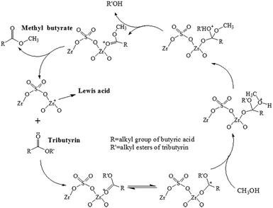
Transesterification is an important acid-catalyzed reaction in biodiesel production.45,46 In this work, transesterification of tributyrin with methanol was used as the probe reaction to test the catalytic performances of the prepared mesoporous sulfated zirconia nanosheets. Fig. S8† shows the tributyrin conversion over SZN-500 as a function of the reaction temperature from 100 °C to 140 °C, and the tributyrin conversion reached nearly 100% at 140 °C. For the SZN-500 catalyst, Lewis acidic sites act as the active sites to catalyze the reaction; thus, the reaction mechanism of transesterification on SZN catalysts was also suggested (Scheme 2). It is well known that transesterification of tributyrin with methanol is a sequential reaction. Tributyrin can be converted stepwise to di- and monobutyrin and finally glycerol. In this case, monobutyrin was taken as a representative of tributyrin to elucidate the transesterification mechanism. The reaction mechanism also can be extended to tributyrin. As depicted in Scheme 2, a carbocation was formed by the interaction of the Lewis acidic sites of the SZN catalyst with the carbonyl oxygen of monobutyrin. The nucleophilic attack of methanol on the carbocation produced a tetrahedral intermediate, which eliminated glycerol and gave one mole of methyl butyrate (RCOOCH3). The SZN catalyst was regenerated after the simultaneous transesterification reactions. The forward reaction occurred continuously through the use of excess methanol, resulting in maximum methyl butyrate yield.As expected, SZN-600 and SZN-700 gave lower tributyrin conversions than SZN-500 under identical reaction conditions due to their less acid sites (Fig. S9†). Moreover, SZN-500 exhibited a higher tributyrin conversion (71.3%) than the SZ-r catalyst (52.7%) (Fig. 11). The two samples have similar acid site amounts as revealed by NH3-TPD, with their differences in catalytic performance greatly related to their morphology and textural structures. Apart from the high catalytic activity, SZN-500 also displayed good reusability. As shown in Fig. 12, it can be seen that SZN-500 still retained 80% of its original activity after the third run. In contrast, SZ-r after the third run only gave 50% of its original activity. For SZ materials, the leaching of S species in the reaction process is the main reason for their activity loss.47 The sulfur content of SZN-500 was 3.2 wt% by EDS analysis after the third run, while that of SZ-r dropped to 1.8 wt%. These results indicated that the good reusability of SZN-500 was ascribed to the strong affinity between S and Zr species as revealed by FTIR results.
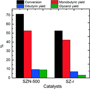 | ||
| Fig. 11 Catalytic performances of the different catalysts in transesterification of tributyrin (reaction conditions: 0.1 g catalyst, 1.3 mmol tributyrin, 52 mmol methanol, 120 °C, 6 h). | ||
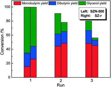 | ||
| Fig. 12 Reusability of the different catalysts for transesterification of tributyrin (reaction conditions: 0.1 g catalyst, 1.3 mmol tributyrin, 52 mmol methanol, 140 °C, 6 h). | ||
Application of the novel strategy
In order to verify the universality of the novel synthesis strategy, various sulphates (Al2(SO4)3, CoSO4, CuSO4, ZnSO4) as sulfate sources and modulators were added into the synthesis system of UiO-66 instead of (NH4)2SO4. The resulting Zr-MOFs-M (M = SAl, SCo, SCu, SZn) samples all showed a flower-like morphology assembled from nanosheets (Fig. S10†), which further confirmed that SO42− species play a vital role in controlling the morphology of Zr-MOFs. The bimetallic oxide nanosheets could be prepared by calcination of the as-synthesized Zr-MOFs-M at a high temperature. This novel synthesis strategy puts forward an alternative route for the preparation of bimetallic oxides with a specific morphology.Conclusions
In summary, a simple novel approach for the preparation of flower-like mesoporous sulfated zirconia nanosheets was developed by thermal decomposition of in situ synthesized sulfated Zr-MOFs for the first time. The SO42− ions in the synthesis system of Zr-MOFs played a crucial role in the manipulation of morphologies of sulfated Zr-MOFs. As the S/Zr molar ratio in the synthesis system reached 0.5, the obtained Zr-MOFs-S showed a flower-like morphology assembled from nanosheets. The sulfated zirconia nanosheets (SZNs) not only inherited the flower-like morphology of their Zr-MOFs-S parent, but also had mesoporous structures and a large surface area (186.1 m2 g−1), and strong bonding between sulfate and zirconia atoms was formed. The calcination temperature has a great influence on the structural properties of SZNs as well as the corresponding catalytic performances. SZN-500 obtained by calcination at 500 °C exhibited good catalytic activity and reusability for the transesterification of tributyrin with methanol due to its specific morphology and textural structures. This novel synthesis strategy is universal and provides an effective synthesis method for functionalized metallic oxides with a specific morphology.Conflicts of interest
There are no conflicts to declare.Acknowledgements
This work was supported by the Natural Science Foundation of China (No. 21576177, 21878203, and 21975174), the Shanxi Provincial Key Innovative Research Team in Science and Technology (No. 2014131006), the Shanxi International Cooperation Project (No. 201703D421037) and the Natural Science Foundation of Shanxi Province of China (No. 201801D121057).Notes and references
- G. D. Yadav and J. J. Nair, Microporous Mesoporous Mater., 1999, 33, 1–48 CrossRef CAS.
- B. M. Reddy and M. K. Patil, Chem. Rev., 2009, 109, 2185–2208 CrossRef CAS.
- K. Saravanan, B. Tyagi and H. C. Bajaj, Appl. Catal., B, 2016, 192, 161–170 CrossRef CAS.
- M. Risch and E. Wolf, Catal. Today, 2000, 62, 255–268 CrossRef CAS.
- M. Risch and E. Wolf, Appl. Catal., A, 1998, 172, L1–L5 CrossRef CAS.
- S. Melada, S. A. Ardizzone and C. L. Bianchi, Microporous Mesoporous Mater., 2004, 73, 203–209 CrossRef CAS.
- D. J. McIntosh and R. A. Kydd, Microporous Mesoporous Mater., 2000, 37, 281–289 CrossRef CAS.
- M. K. Mishra, B. Tyagi and R. V. Jasra, Ind. Eng. Chem. Res., 2003, 42, 5727–5736 CrossRef CAS.
- C. Y. Di, X. F. Li, P. Wang, Z. H. Li, B. B. Fan and T. Dou, Petrol. Sci., 2017, 14, 203–213 CrossRef CAS.
- S. Hu, J. Shan, Q. Zhang, Y. Wang, Y. Liu, Y. Gong, Z. Wu and T. Dou, Appl. Catal., A, 2012, 445-446, 215–220 CrossRef CAS.
- Y. Shang, W. Wang, Y. Zhai, Y. Song, X. Zhao, T. Ma, J. Wei and Y. Gong, Microporous Mesoporous Mater., 2019, 276, 173–182 CrossRef CAS.
- J. L. C. Rowsell and O. M. Yaghi, Microporous Mesoporous Mater., 2004, 73, 3–14 CrossRef CAS.
- O. K. Farha, I. Eryazici, N. C. Jeong, B. G. Hauser, C. E. Wilmer, A. A. Sarjeant, R. Q. Snurr, S. T. Nguyen, A. Ö. Yazaydın and J. T. Hupp, J. Am. Chem. Soc., 2012, 134, 15016–15021 CrossRef CAS.
- H. C. Zhou and S. Kitagawa, Chem. Soc. Rev., 2014, 43, 5415–5418 RSC.
- D. Liu, J. P. Lang and B. F. Abrahams, J. Am. Chem. Soc., 2011, 133, 11042–11045 CrossRef CAS.
- F. L. Hu, Y. Mi, C. Zhu, B. F. Abrahams, P. Braunstein and J. P. Lang, Angew. Chem., Int. Ed., 2018, 57, 12696–12701 CrossRef CAS.
- W. X. Li, J. H. Gu, H. X. Li, M. Dai, D. J. Young, H. Y. Li and J. P. Lang, Inorg. Chem., 2018, 57, 13453–13460 CrossRef CAS.
- W. H. Zhang, Z. G. Ren and J. P. Lang, Chem. Soc. Rev., 2016, 45, 4995–5019 RSC.
- F. L. Li, P. Wang, X. Huang, D. J. Young, H. F. Wang, P. Braunstein and J. P. Lang, Angew. Chem., Int. Ed., 2019, 58, 7051–7056 CrossRef CAS.
- P. Q. Liao, J. Q. Shen and J. P. Zhang, Coord. Chem. Rev., 2018, 373, 22–28 CrossRef CAS.
- F. L. Li, Q. Shao, X. Huang and J. P. Lang, Angew. Chem., Int. Ed., 2018, 57, 1888–1892 CrossRef CAS.
- X. Han, H. G. W. Godfrey, L. Briggs, A. J. Davies, Y. Cheng, L. L. Daemen, A. M. Sheveleva, F. Tuna, E. J. L. Mclnnes, J. Sun, C. Drathen, M. W. George, A. J. Ramirez-Cuesta, K. M. Thomas, S. Yang and M. Schröder, Nat. Mater., 2018, 17, 691–696 CrossRef CAS.
- J. Liu, L. Chen, H. Cui, J. Zhang, L. Zhang and C. Y. Su, Chem. Soc. Rev., 2014, 43, 6011–6061 RSC.
- Z. Hasan, D.-W. Cho, I.-H. Nam, C.-M. Chon and H. Song, Materials, 2016, 9, 261 CrossRef.
- Y. Su, C. Chen, X. Zhu, Y. Zhang, W. Gong, H. Zhang, H. Zhao and G. Wang, Dalton Trans., 2017, 46, 6358–6365 RSC.
- J. Meng, C. Niu, L. Xu, J. Li and L. Mai, J. Am. Chem. Soc., 2017, 139, 8212–8221 CrossRef CAS.
- L. Oar-Arteta, T. Wezendonk, X. Sun, F. Kapteijn and J. Gascon, Mater. Chem. Front., 2017, 1, 1709–1745 RSC.
- N. Stock and S. Biswas, Chem. Rev., 2012, 112, 933–969 CrossRef CAS.
- W. Cho, H. J. Lee and M. Oh, J. Am. Chem. Soc., 2008, 130, 16943–16946 CrossRef CAS.
- X. Yan, N. Lu, B. Fan, J. Bao, D. Pan, M. Wang and R. Li, CrystEngComm, 2015, 17, 6426–6433 RSC.
- C. Zlotea, D. Phanon, M. Mazaj, D. Heurtaux, V. Guillerm, C. Serre, P. Horcajada, T. Devic, E. Magnier, F. Cuevas, G. Férey, P. L. Llewellyn and M. Latroche, Dalton Trans., 2011, 40, 4879–4881 RSC.
- G. C. Shearer, S. Chavan, J. Ethiraj, J. G. Vitillo, S. Svelle, U. Olsbye, C. Lamberti, S. Bordiga and K. P. Lillerud, Chem. Mater., 2014, 26, 4068–4071 CrossRef CAS.
- N. Lu, F. Zhou, H. Jia, H. Wang, B. Fan and R. Li, Ind. Eng. Chem. Res., 2017, 56, 14155–14163 CrossRef CAS.
- Y. Han, M. Liu, K. Li, Y. Zuo, Y. Wei, S. Xu, G. Zhang, C. Song, Z. Zhang and X. Guo, CrystEngComm, 2015, 17, 6434–6440 RSC.
- C. Atzori, G. C. Shearer, L. Maschio, B. Civalleri, F. Bonino, C. Lamberti, S. Svelle, K. P. Lillerud and S. Bordiga, J. Phys. Chem. C, 2017, 121, 9312–9324 CrossRef CAS.
- L. Zhou, X. Zhang and Y. Chen, Mater. Lett., 2017, 197, 167–170 CrossRef CAS.
- W. Morris, S. Wang, D. Cho, E. Auyeung, P. Li, O. K. Farha and C. A. Mirkin, ACS Appl. Mater. Interfaces, 2017, 9, 33413–33418 CrossRef CAS.
- T. Tsuruoka, S. Furukawa, Y. Takashima, K. Yoshida, S. Isoda and S. Kitagawa, Angew. Chem., Int. Ed., 2009, 48, 4739–4743 CrossRef CAS PubMed.
- M. Ejtemaei, A. Tavakoli, N. Charchi, B. Bayati, A. A. Babaluo and Y. Bayat, Adv. Powder Technol., 2014, 25, 840–846 CrossRef CAS.
- E. Silva Junior, S. G. Antonio and E. Longo, Ceram. Int., 2018, 44, 3517–3522 CrossRef CAS.
- M. Verma, V. Kumar and A. Katoch, Mater. Chem. Phys., 2018, 212, 268–273 CrossRef CAS.
- T. Yamaguchi, T. Jin and K. Tanabe, J. Phys. Chem., 1986, 90, 3148–3152 CrossRef CAS.
- V. G. Deshmane and Y. G. Adewuyi, Appl. Catal., A, 2013, 462-463, 196–206 CrossRef CAS.
- Z. Miao, J. Zhou, J. Zhao, D. Liu, X. Bi, L. Chou and S. Zhuo, Appl. Surf. Sci., 2017, 411, 419–430 CrossRef CAS.
- E. G. Taques Filho, E. L. Dall'Oglio, P. T. de Sousa Jr, L. Gomes de Vasconcelos and C. A. Kuhnen, Energy Fuels, 2016, 30, 4806–4819 CrossRef.
- N. Narkhede and A. Patel, Ind. Eng. Chem. Res., 2013, 52, 13637–13644 CrossRef CAS.
- K. Saravanan, B. Tyagi, R. S. Shukla and H. C. Bajaj, Fuel, 2016, 165, 298–305 CrossRef CAS.
Footnote |
| † Electronic supplementary information (ESI) available. See DOI: 10.1039/c9ce01456j |
| This journal is © The Royal Society of Chemistry 2020 |

