A NiRhS fuel cell catalyst – lessons from hydrogenase†
Seiji
Ogo
 *ab,
Tatsuya
Ando
ab,
Le Tu Thi
Minh
a,
Yuki
Mori
a,
Takahiro
Matsumoto
ab,
Takeshi
Yatabe
ab,
Ki-Seok
Yoon
ab,
Yukio
Sato
c,
Takashi
Hibino
 bd and
Kenji
Kaneko
 bc
bc
aDepartment of Chemistry and Biochemistry, Graduate School of Engineering, Kyushu University, International Institute for Carbon-Neutral Energy Research (WPI-I2CNER), Kyushu University, 744 Moto-oka, Nishi-ku, Fukuoka 819-0395, Japan. E-mail: ogo.seiji.872@m.kyushu-u.ac.jp
bCenter for Small Molecule Energy, Kyushu University, 744 Moto-oka, Nishi-ku, Fukuoka 819-0395, Japan
cDepartment of Materials Science and Engineering, Faculty of Engineering, Kyushu University, 744 Moto-oka, Nishi-ku, Fukuoka 819-0395, Japan
dGraduate School of Environmental Studies, Nagoya University, Furo-cho, Chikusa-ku, Nagoya 464-8601, Japan
First published on 3rd September 2020
Abstract
We present a novel fuel cell heterogeneous catalyst based on rhodium, nickel and sulfur with power densities 5–28% that of platinum. The NiRhS heterogeneous catalyst was developed via a homogeneous model complex of the [NiFe]hydrogenases (H2ases) and can act as both the cathode and anode of a fuel cell.
We have previously reported a NiRu model complex, [NiII(X)(H2O)(μ-H)RuII(η6-C6Me6)](NO3) {[3](NO3), X = N,N′-dimethyl-3,7-diazanonane-1,9-dithiolato}, which can mimic the chemical functions of O2-tolerant [NiFe]H2ases.1–3 This complex is based on a central NiRu bimetallic core with flexible μ-S bridges, which allow the close approach of the two metal centres. This complex can perform both H2-oxidation and O2-reduction, in a similar manner to O2-tolerant [NiFe]H2ases,1,3,4 and thus acts as both an anode and a cathode catalyst for H2–O2 fuel cells.5 However, the successful functioning of the compound did not extend as far as producing an efficient fuel cell.5 Since organometallic catalysts are not as robust as their solid-state, heterogeneous counterparts, we investigated the possibility of using dry distillation (pyrolysis) to remove the volatile elements and leave behind the active μ-S bimetallic core. We investigated three bimetallic complexes, where nickel was partnered with ruthenium, rhodium and iridium and the NiRh complex gave the best results.
Herein, we describe the synthesis, characteristics and catalytic properties of the NiRh organometallic complex before detailing its conversion into NiRhS dry-distilled catalysts (DDCs). We then demonstrate the catalytic properties of these dry-distilled compounds and their application as the first DDCs containing two different metals and sulfur that function as both the anode and cathode of functioning fuel cells (Fig. S1 and Table S1, ESI†).6
A NiIIRhIII dichloride complex [NiIICl(X)RhIIICl(η5-C5Me5)] (1) was prepared from the reaction of [NiII(X)] with [RhIII(η5-C5Me5)Cl2]2. This water-soluble complex was then characterized by X-ray analysis (Fig. S2 and Table S2, ESI†), electrospray ionization-mass spectrometry (ESI-MS, Fig. S3, ESI†) and 1H NMR (Fig. S4, ESI†) and IR spectroscopies (Fig. S5, ESI†). Its structure is based around a Ni(μ-S)2Rh butterfly core, which is similar to our previously-reported [NiFe]H2ase mimics.1,7
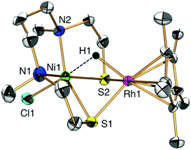
Having synthesized 1, we proceeded to investigate its catalytic properties. Complex 1 activated H2 (0.1 MPa) heterolytically in water to afford a NiIIRhIII hydride complex [NiIICl(X)(μ-H)RhIII(η5-C5Me5)] (2) in a similar manner to H2ases (Fig. 1 and 2a).1,3,7,8 The structure was determined by X-ray analysis (Fig. 1), UV-vis spectroscopy (Fig. S6 and Tables S2 and S3, ESI†), ESI-MS (Fig. S7, ESI†) and IR spectroscopy (Fig. S8, ESI†). The X-ray analysis showed that the Ni1⋯Rh1 interatomic distance had been shortened to 2.7454(16) Å, with a bridging hydride ligand between the two metal centres (Fig. 1). This structural change upon the activation of H2 and complexation of the hydride is similar to that found in our other [NiFe]H2ase models and the natural [NiFe]H2ases themselves.1,7,9 The origin of the bridging hydride was derived from dihydrogen gas, as confirmed by the formation of a deuteride complex [NiIICl(X)(μ-D)RhIII(η5-C5Me5)] (D-labelled 2) from the treatment of 1 with D2 (Fig. S7 and S8, ESI†).
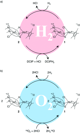 | ||
| Fig. 2 Proposed catalytic reaction mechanisms for (a) H2-oxidation and (b) O2-reduction with NiRh complexes in water. DCIP: 2,6-dichlorobenzeneindophenol. DCIPH2: reduced-form of DCIP. | ||
We then investigated the catalytic properties of 1 by using 2,6-dichlorobenzeneindophenol (DCIP) as an acceptor of 2e− and 2H+ under stoichiometric conditions with 2 and catalytic conditions with 1 (eqn (1)). Under stoichiometric conditions (2![[thin space (1/6-em)]](https://www.rsc.org/images/entities/char_2009.gif) :
:![[thin space (1/6-em)]](https://www.rsc.org/images/entities/char_2009.gif) DCIP = 1
DCIP = 1![[thin space (1/6-em)]](https://www.rsc.org/images/entities/char_2009.gif) :
:![[thin space (1/6-em)]](https://www.rsc.org/images/entities/char_2009.gif) 1) in the absence of H2 in water, 2 is capable of reducing DCIP to DCIPH2 (Fig. S9, S10 and Table S3, ESI†). Under catalytic conditions (1
1) in the absence of H2 in water, 2 is capable of reducing DCIP to DCIPH2 (Fig. S9, S10 and Table S3, ESI†). Under catalytic conditions (1![[thin space (1/6-em)]](https://www.rsc.org/images/entities/char_2009.gif) :
:![[thin space (1/6-em)]](https://www.rsc.org/images/entities/char_2009.gif) DCIP = 1
DCIP = 1![[thin space (1/6-em)]](https://www.rsc.org/images/entities/char_2009.gif) :
:![[thin space (1/6-em)]](https://www.rsc.org/images/entities/char_2009.gif) 27) in the presence of H2 in water (buffer solution), H2 reduces DCIP to DCIPH2 with the assistance of 1 (Fig. 2a). The catalytic reaction is pH-dependent (Fig. S11 and Table S4, ESI†) and it shows a maximum turnover number (TON) value of 14.3–15.2 at pH 4.0–5.0 (TON, mol of DCIPH2/mol of 1), similar to our previously reported system.4
27) in the presence of H2 in water (buffer solution), H2 reduces DCIP to DCIPH2 with the assistance of 1 (Fig. 2a). The catalytic reaction is pH-dependent (Fig. S11 and Table S4, ESI†) and it shows a maximum turnover number (TON) value of 14.3–15.2 at pH 4.0–5.0 (TON, mol of DCIPH2/mol of 1), similar to our previously reported system.4
 | (1) |
The hydride complex 2 can also reduce O2 to H2O (Fig. 2b, Fig. S12 and Table S3, ESI†). The O2-reduction in water was confirmed by an 18O2-experiment wherein H218O was formed from the reaction of 2 with 18O2, as observed by gas chromatography-mass spectrometry (GC-MS). The TON value (TON, [(mol of H218O)/(mol of 1)]/2) was determined to be 0.48 in the reaction using 1 with H2 as an electron donor (Table S4, ESI†).10–12
Having satisfied ourselves that the NiRh catalyst was a successful analogue of our NiRu catalyst, we set about rendering it in a heterogeneous, solid-state form. To achieve this, we used dry distillation of 1 with carbon black, in pyrolysis experiments at 100–800 °C under vacuum (ca. 15–20 Pa).13 Following this process, the volatile elements were removed to mainly leave Ni, Rh and S atoms. The structural properties of the resulting solids were analysed by thermogravimetry–differential scanning calorimetry (TG–DSC), X-ray photoelectron spectroscopy (XPS), elemental analysis, X-ray powder diffraction (XRD) analysis, (scanning) transmission electron microscopy ((S)TEM) and energy-dispersive X-ray spectroscopy (EDS) mapping (Table S5, ESI†).
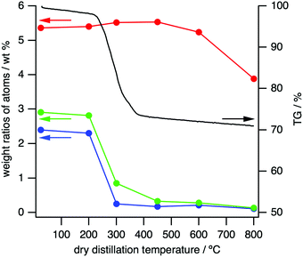
The thermal properties of 1 were investigated by TG–DSC under an N2 atmosphere (Fig. 3 and Fig. S13, ESI†). Weight loss began around 250 °C and was mostly completed by about 400–450 °C. Some endothermic peaks in the process suggest vaporization of the decomposed products that should mainly contain Cl, H and N atoms, as detailed below.
XPS measurements also show that the structural change of 1 depends on the temperature of dry distillation (Fig. S14, ESI†). Above 300 °C, the binding energies at 162.3–163.6 eV for S 2p3/2, 307.4–307.8 eV for Rh 3d5/2 and 853.0 eV for Ni 2p3/2 are observed in the XP spectra, which might be derived from metal sulfides coexisting with Rh0.6c,14,15
XRD analysis also indicates the transformation of 1 to DDCs depending on the dry distillation temperatures (Fig. S15, ESI†). Complex 1 should change to DDCs at 200–300 °C and then the DDCs could be structurally changed further at 700–800 °C. The XRD patterns of DDCs prepared at 300–700 °C seem to be similar to those of Rh17S15 and Rh3S4,15 but do not completely correspond to them. The DDC prepared at 800 °C might be attributed to the S-doped NiRh alloy.14b
Elemental analyses were performed to determine the ratios of C![[thin space (1/6-em)]](https://www.rsc.org/images/entities/char_2009.gif) :
:![[thin space (1/6-em)]](https://www.rsc.org/images/entities/char_2009.gif) H
H![[thin space (1/6-em)]](https://www.rsc.org/images/entities/char_2009.gif) :
:![[thin space (1/6-em)]](https://www.rsc.org/images/entities/char_2009.gif) N
N![[thin space (1/6-em)]](https://www.rsc.org/images/entities/char_2009.gif) :
:![[thin space (1/6-em)]](https://www.rsc.org/images/entities/char_2009.gif) S, according to the heating temperatures (Fig. 3 and Table S6, ESI†). The ratio of N decreased from 2.30% to only 0.25% upon raising the heating temperature from 200 °C to 300 °C, with a similar trend for H (Table S6, ESI†). These profiles are almost the same as the TG curve shown in Fig. 3 and strongly indicate that the weight loss at 200–300 °C is caused by vaporization of N- and H-containing fragments. S, however, only deceased from 5.36% to 3.88%, even after heating to 800 °C, indicating that the DDCs bear significant amounts of this element.
S, according to the heating temperatures (Fig. 3 and Table S6, ESI†). The ratio of N decreased from 2.30% to only 0.25% upon raising the heating temperature from 200 °C to 300 °C, with a similar trend for H (Table S6, ESI†). These profiles are almost the same as the TG curve shown in Fig. 3 and strongly indicate that the weight loss at 200–300 °C is caused by vaporization of N- and H-containing fragments. S, however, only deceased from 5.36% to 3.88%, even after heating to 800 °C, indicating that the DDCs bear significant amounts of this element.
Bright-field (BF-)TEM, annular dark field (ADF-)STEM and STEM-EDS analyses were conducted to analyse the particle form and elemental distribution in the DDCs (Fig. 4 and Fig. S16, ESI†). At heating temperatures above 200 °C, nanoparticles with a particle size of 50 nm or less were formed. Elemental mapping reveals that Ni, Rh and S atoms are distributed homogeneously under 280 °C but inhomogeneously above 300 °C.
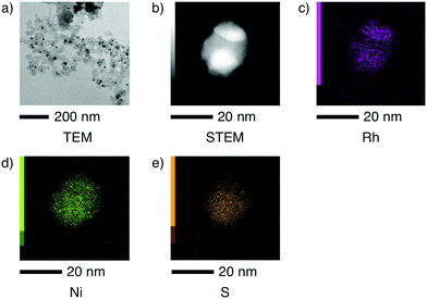 | ||
| Fig. 4 (a) BF-TEM image, (b) ADF-STEM image and STEM-EDS elemental mappings of (c) Rh, (d) Ni and (e) S of the dry-distilled catalyst (DDC) prepared at 600 °C. | ||
Based on these results, we conclude that the homogeneous NiII(μ-S)2RhIII catalyst is converted into heterogeneous NiRhS-based catalysts by loss of N, H and Cl atoms at 300–600 °C, with a slight loss of S atoms at 800 °C.15
To examine the catalytic activities of DDCs, H2-oxidation and 18O2-reduction are investigated in flask experiments. The DDCs are able to remember the reactivity of 1 to catalytically oxidize H2 and reduce 18O2. The composition of NiRhS should remind us of [NiFe]H2ases. The TON values of H2-oxidation and 18O2-reduction are increased to 4.3 and 3.5 times higher than those of 1, respectively, by dry distillation (Tables S4 and S7, ESI†).
Following the successful enhancement of the catalytic activities by dry distillation, we assembled polymer electrolyte fuel cells (PEFCs) with 1 or DDCs as anode and/or cathode catalysts (Fig. S17, ESI†). A membrane electrode assembly (MEA) with Nafion membrane was made in the same way as molecular fuel cells.5,16
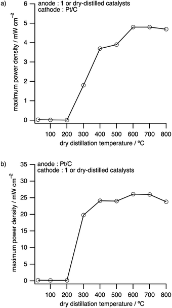
The dependence of the maximum power densities on the dry distillation temperatures was investigated with DDCs as electrode catalysts for either the anode or the cathode (Fig. 5, Fig. S18, S19 and Tables S4 and S8, ESI†). The maximum power densities and open circuit voltages (OCVs) obtained, where DDCs were employed as the anode and Pt/C as the cathode, were significantly enhanced above 300 °C (Fig. 5a). The highest maximum power density of 4.85 mW cm−2 and OCV of 1.00 V were obtained by using the DDC prepared at 600 °C (Fig. 5a, Fig. S18 and Table S8, ESI†). This maximum power density is 164 times higher than that of the precursor 1 and nearly 5% of that of Pt. Thereafter, the same catalysts were applied as the cathode to fabricate and evaluate PEFCs. As before, the performance was drastically enhanced above the dry distillation temperature of 300 °C, with the DDC prepared at 600 °C exhibiting the best performance with an OCV of 0.78 V and a maximum power density of 26.1 mW cm−2, which is 28% of that of Pt (Fig. 5b, Fig. S19 and Table S8, ESI†). This power density is 139 times higher than that of 1.17
Electrochemical aspects for H2-oxidation and O2-reduction with 1 and the DDC prepared at 600 °C were investigated by means of Tafel plots and impedance spectra (Fig. S20, S21 and Table S9, ESI†). Exchange current densities of 0.0286 mA cm−2 and 0.0161 mA cm−2 were estimated for H2-oxidation and O2-reduction with 1, respectively, by Tafel plots (Fig. S20 and Table S9, ESI†), which are slightly lower than those of our previously reported NiIIRuII complex.18 The exchange current densities can drastically increase by dry distillation, as determined to be 13.9 mA cm−2 for H2-oxidation and 10.5 mA cm−2 for O2-reduction, respectively, by using the DDC prepared at 600 °C (Fig. S20, ESI†). This means that the DDC has higher charge-transfer ability on the electrode. In impedance spectra, no Warburg impedances were observed for the DDC, which indicates fast gas diffusion and rapid dissociative adsorption, different from 1 (Fig. S21, ESI†).
Finally, we investigated the characteristics of a fuel cell using the DDCs prepared at 600 °C as both the anode and the cathode (Fig. S22b and Tables S4, S8, ESI†). The fuel cell generated an OCV of 0.78 V and a maximum power density of 4.53 mW cm−2, a 449-fold improvement in maximum power density over 1 as a catalyst for both electrodes (Fig. S22, ESI†).
In this paper, we have shown that a Rh analogue of our previous [NiFe]H2ase models successfully functions in a similar manner. Crucially, however, we have been able to transform it by dry distillation into heterogeneous catalysts with maximum power densities 5–28% that of platinum. While these new catalysts fall short of the performance of platinum, they point the way towards linking the stepwise development of new, heterogeneous, fuel cell catalysts with the development of homogeneous organometallic catalysts.
This work was supported by JST CREST Grant Number JPMJCR18R2, Japan, JSPS KAKENHI Grant Numbers JP26000008 (Specially Promoted Research), JP18H02091, and JP19K05503 and the World Premier International Research Center Initiative (WPI), Japan.
Conflicts of interest
There are no conflicts to declare.Notes and references
- (a) S. Ogo, R. Kabe, K. Uehara, B. Kure, T. Nishimura, S. C. Menon, R. Harada, S. Fukuzumi, Y. Higuchi, T. Ohhara, T. Tamada and R. Kuroki, Science, 2007, 316, 585 CrossRef CAS; (b) S. Ogo, Coord. Chem. Rev., 2017, 334, 43 CrossRef CAS.
- (a) X. Yang, L. C. Elrod, J. H. Reibenspies, M. B. Hall and M. Y. Darensbourg, Chem. Sci., 2019, 10, 1368 RSC; (b) C. Wombwell, C. A. Caputo and E. Reisner, Acc. Chem. Res., 2015, 48, 2858 CrossRef CAS.
- W. Lubitz, H. Ogata, O. Rüdiger and E. Reijerse, Chem. Rev., 2014, 114, 4081 CrossRef CAS.
- (a) T. Matsumoto, B. Kure and S. Ogo, Chem. Lett., 2008, 37, 970 CrossRef CAS; (b) T. Matsumoto, T. Ando, Y. Mori, T. Yatabe, H. Nakai and S. Ogo, J. Organomet. Chem., 2015, 796, 73 CrossRef CAS.
- T. Matsumoto, K. Kim and S. Ogo, Angew. Chem., Int. Ed., 2011, 50, 11202 CrossRef CAS.
- (a) N. Singh, M. Gordon, H. Metiu and E. McFarland, J. Appl. Electrochem., 2016, 46, 497 CrossRef CAS; (b) Y. Shimizu, S. Yamamoto and M. Ono, Jpn. Kokai Tokkyo Koho, 2007, JP 200787827 Search PubMed; (c) B. Chen, G. Ma, Y. Zhu, J. Wang, W. Xiong and Y. Xia, J. Power Sources, 2016, 334, 112 CrossRef CAS; (d) Y. Li and T. V. Nguyen, J. Power Sources, 2018, 382, 152 CrossRef CAS; (e) R. W. Reeve, P. A. Christensen, A. J. Dickinson, A. Hamnett and K. Scott, Electrochim. Acta, 2000, 45, 4237 CrossRef CAS; (f) M. Shen, C. Ruan, Y. Chen, C. Jiang, K. Ai and L. Lu, ACS Appl. Mater. Interfaces, 2015, 7, 1207 CrossRef CAS; (g) F. Wang, P. Zhang, S. You, J. Du, B. Jiang, X. Li, Z. Cai, N. Ren and J. Zou, J. Colloid Interface Sci., 2020, 567, 65 CrossRef CAS; (h) Y. Sun, Y. Dai, Y. Duan, X. Xu, Y. Lv, L. Yang and J. Zou, Carbon, 2017, 119, 394 CrossRef CAS; (i) D. Guo, S. Han, R. Ma, Y. Zhou, Q. Liu, J. Wang and Y. Zhu, Microporous Mesoporous Mater., 2018, 270, 1 CrossRef CAS; (j) P. Chandran, A. Ghosh and S. Ramaprabhu, Sci. Rep., 2018, 8, 3591 CrossRef; (k) F. Möller, S. Piontek, R. G. Miller and U.-P. Apfel, Chem. – Eur. J., 2018, 24, 1471 CrossRef.
- S. Ogo, K. Ichikawa, T. Kishima, T. Matsumoto, H. Nakai, K. Kusaka and T. Ohhara, Science, 2013, 339, 682 CrossRef CAS.
- (a) R. M. Bullock and M. L. Helm, Acc. Chem. Res., 2015, 48, 2017 CrossRef CAS; (b) B. C. Manor and T. B. Rauchfuss, J. Am. Chem. Soc., 2013, 135, 11895 CrossRef CAS.
- H. Ogata, K. Nishikawa and W. Lubitz, Nature, 2015, 520, 571 CrossRef.
- T. Kishima, T. Matsumoto, H. Nakai, S. Hayami, T. Ohta and S. Ogo, Angew. Chem., Int. Ed., 2016, 55, 724 CrossRef CAS.
- P. Wulff, C. C. Day, F. Sargent and F. A. Armstrong, Proc. Natl. Acad. Sci. U. S. A., 2014, 111, 6606 CrossRef CAS.
- J. Fritsch, O. Lenz and B. Friedrich, Nat. Rev. Microbiol., 2013, 11, 106 CrossRef CAS.
- F. A. Westerhaus, R. V. Jagadeesh, G. Wienhöfer, M.-M. Pohl, J. Radnik, A.-E. Surkus, J. Rabeah, K. Junge, H. Junge, M. Nielsen, A. Brückner and M. Beller, Nat. Chem., 2013, 5, 537 CrossRef CAS.
- (a) J. F. Moulder, W. F. Stickle, P. E. Sobol and K. D. Bomben, Handbook of X-ray Photoelectron Spectroscopy, Physical Electronics Inc., Minnesota, 1995 Search PubMed; (b) J. Lu, Z. Tang, L. Luo, S. Yin, P. K. Shen and P. Tsiakaras, Appl. Catal., B, 2019, 255, 117737 CrossRef CAS.
- J. Masud, T. V. Nguyen, N. Singh, E. McFarland, M. Ikenberry, K. Hohn, C.-J. Pan and B.-J. Hwang, J. Electrochem. Soc., 2015, 162, F455 CrossRef CAS.
- S. P. Annen, V. Bambagioni, M. Bevilacqua, J. Filippi, A. Marchionni, W. Oberhauser, H. Schönberg, F. Vizza, C. Bianchini and H. Grützmacher, Angew. Chem., Int. Ed., 2010, 49, 7229 CrossRef CAS.
- M. Lefèvre, J. P. Dodelet and P. Bertrand, J. Phys. Chem. B, 2002, 106, 8705 CrossRef.
- T. Matsumoto, K. Kim, H. Nakai, T. Hibino and S. Ogo, ChemCatChem, 2013, 5, 1368 CrossRef CAS.
Footnote |
| † Electronic supplementary information (ESI) available: Experimental details, Tables S1–S9 and Fig. S1–S22. CCDC 1996959 and 1996960. For ESI and crystallographic data in CIF or other electronic format see DOI: 10.1039/d0cc04789a |
| This journal is © The Royal Society of Chemistry 2020 |

