 Open Access Article
Creative Commons Attribution 3.0 Unported Licence
Low-gap zinc porphyrin as an efficient dopant for photomultiplication type photodetectors†
Mariza
Mone
a,
Kaixuan
Yang
b,
Petri
Murto
 c,
Fujun
Zhang
 *b and
Ergang
Wang
 *ad
*ad
aDepartment of Chemistry and Chemical Engineering/Applied Chemistry, Chalmers University of Technology, Gothenburg, SE-412 96, Sweden. E-mail: ergang@chalmers.se
bSchool of Science, Beijing Jiaotong University, Beijing 100044, China. E-mail: fjzhang@bjtu.edu.cn
cDepartment of Chemistry, University of Cambridge, Cambridge CB2 1EW, UK
dSchool of Materials Science and Engineering, Zhengzhou University, Zhengzhou 450001, China
First published on 11th September 2020
Abstract
A new zinc porphyrin, named as Por4IC, was synthesized, which through extension of conjugation and an enhancement of planarity and donor–acceptor interactions exhibits a very low band gap. The molecule was able to efficiently facilitate a photomultiplication effect in blend with P3HT which was assisted by electron trapping followed by hole tunneling injection from the Al electrode giving rise to a high external quantum efficiency of 22![[thin space (1/6-em)]](https://www.rsc.org/images/entities/char_2009.gif) 182% and a specific detectivity of 4.4 × 10¹² Jones at 355 nm and at −15 V bias. This work introduces porphyrin derivatives as promising dopants for photomultiplication type photodetectors.
182% and a specific detectivity of 4.4 × 10¹² Jones at 355 nm and at −15 V bias. This work introduces porphyrin derivatives as promising dopants for photomultiplication type photodetectors.
Organic photodetectors (OPDs) are devices that can sense and convert an incident photon into an electrical signal, finding applications in fields like image sensing, light communication and biomedical sensing.1,2 Organic semiconducting materials benefit from high absorption coefficients, adjustable frontier orbital energy levels, the ease of solution-based fabrication and low production cost.3,4 Typical OPDs are of photodiode types,5 which show the advantages of low background noise and fast photoresponse. However, their efficiency is normally less than 100% since the operational mechanism follows a photovoltaic effect, limiting their practical applications under poor flux light conditions.6 In many cases, the light that needs to be detected is weak, and there is a demand to enhance the photoresponse of the detectors under such conditions.7 In order to intensify the output current signal of photodiode type photodetectors, a common approach is to integrate a number of transistors as amplifier circuits in the device.8 Another approach that can be implemented to improve the EQE is to construct photodetectors that can multiply the photocurrent and thus be able to achieve efficiencies of carrier generation exceeding unity.4,5 The latter types of photodetectors are known as photomultiplication (PM) type photodetectors.
After the first PM type OPD was reported in 1994,9 studies on PM type OPDs were done with a focus on understanding the mechanism of photomultiplication in organic materials,6 developing more efficient devices7,8 and making devices with specific spectral responses (broadband or narrowband).9,10 The mechanism of photomultiplication is based on trapping of the photogenerated electrons, and the molecules that can act as traps have been developed and employed either for the interfacial layer or the active layer of the devices. The most commonly utilized traps in the photoactive layer are fullerene derivatives PC61BM and PC71BM in blend with poly(3-hexylthiophene) (P3HT). Such PM type OPDs have shown external quantum efficiencies (EQEs) surpassing 100% and detectivities ranging from 1010 to 1013 Jones.11–13 However, fullerene derivatives possess well-known drawbacks of low absorption coefficients, fixed energy levels and poor stability of the blend morphology.14,15
A number of fullerene-free devices have been fabricated showing excellent results. The reported EQEs were intriguingly high, in some cases surpassing 20![[thin space (1/6-em)]](https://www.rsc.org/images/entities/char_2009.gif) 000%, while the detectivities were also promising, with the record value being 1.43 × 10¹⁴ Jones and the dark current density (JD) ranging from 10−2 to 10−1 mA cm−2. However, the best reported values are obtained in rather high applied voltages in the range of −20 V.5,16,17 There are only few non-fullerene materials evaluated as dopants for PM type OPDs, offering further potential for the improvement in regard to maintaining high efficiencies in a broader optical spectrum and with lower applied voltages.
000%, while the detectivities were also promising, with the record value being 1.43 × 10¹⁴ Jones and the dark current density (JD) ranging from 10−2 to 10−1 mA cm−2. However, the best reported values are obtained in rather high applied voltages in the range of −20 V.5,16,17 There are only few non-fullerene materials evaluated as dopants for PM type OPDs, offering further potential for the improvement in regard to maintaining high efficiencies in a broader optical spectrum and with lower applied voltages.
Porphyrins often show high absorption coefficients in a long wavelength range,8 while their energy levels can be easily tuned with appropriate molecular design to match those of donor materials,18 to form efficient charge traps in blend films. It is known that in order to form efficient electron or hole traps, the LUMO or HOMO offsets, respectively, between the host and dopant molecules should be large enough. Therefore, for a porphyrin to effectively trap electrons in blend with P3HT the LUMO energy level should be downshifted to achieve a sufficient LUMO–LUMO offset.
In this work, a new porphyrin molecule Por4IC was synthesized and used as an optical sensitizer in PM type OPDs. The low-gap Por4IC featured two strong absorption peaks spanning from the visible to the near-infrared spectral region and a very high absorption coefficient. The molecule possessed a downshifted LUMO energy level, making it a favorable acceptor in blend with P3HT. Upon fabrication of OPD devices, the low concentration of Por4IC in the active layer – in combination with its designed energy levels – gave rise to a successful PM effect. As a result, exceptional device characteristics were observed with an EQE as high as 22![[thin space (1/6-em)]](https://www.rsc.org/images/entities/char_2009.gif) 182% and the detectivity reaching 4.4 × 10¹² Jones at 355 nm and at −15 V bias.
182% and the detectivity reaching 4.4 × 10¹² Jones at 355 nm and at −15 V bias.
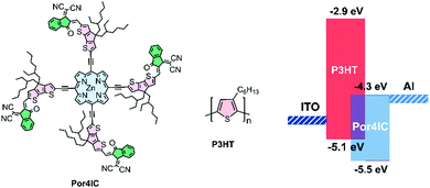
The chemical structures of Por4IC and P3HT are shown in Scheme 1, while the synthetic procedures are detailed in the ESI.† The Zn containing porphyrin core structure, initially synthesized by the Lindsey method,19 was connected through acetylenic bridges in the meso positions with the fused-ring 4,4-bis(2-ethylhexyl)-4H-cyclopenta[2,1-b:3,4-b′]dithiophene (CPDT) via a Sonogashira coupling reaction. The CPDT groups (coloured pink in Scheme 1) were added to extend the conjugation of the porphyrin and to ensure sufficient solubility. The fused-ring derivatives tend to extend the conjugation by enhancing the planarity and rigidity of the structures, effectively reducing the HOMO–LUMO energy separation and facilitating close intermolecular interactions.20 Moreover, the molecule was functionalized with electron-withdrawing 2-(3-oxo-2,3-dihydro-1H-inden-1-ylidene)malononitrile (IC) end groups (coloured green in Scheme 1). IC and its derivatives are commonly used end-capping groups in the synthesis of well-functioning small molecule acceptors for organic photovoltaic applications,21 and in this work IC groups were accordingly added to down-shift the LUMO energy of Por4IC making it an ideal acceptor material in blend with P3HT. The synthesized porphyrin structure was confirmed using NMR spectroscopy and MALDI-TOF mass spectrometry.
 | ||
| Scheme 1 (a) Chemical structures of Por4IC and P3HT and (b) Energy level diagram of Por4IC and P3HT. | ||
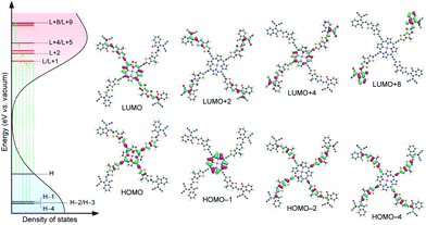
Density functional theory (DFT) calculations were employed to gain an insight into the conformation, electronic transitions and vacant electronic states of Por4IC. The molecule features a co-planar ground-state conformation which is only slightly distorted in toluene solution, as compared to the structure in the gas phase (Fig. S5, ESI†). This translates to ca. 0.05 eV difference between the lowest-energy excited state (S1) calculated in toluene and the gas phase, suggesting only a minor change in the optical absorption in different polarity environments. The left side of Fig. 1 shows the optically accessible density of states (DOS) of Por4IC in toluene solution, including the most relevant electronic transitions (green arrows). The corresponding frontier orbitals are depicted on the right side of Fig. 1. Note that only one of the degenerate orbital pairs is shown here; the calculated transition energies and the contributing orbitals are included in detail in Fig. S5 and Table S1 (ESI†). The optical absorption is dominated by degenerate low-energy HOMO → LUMO and HOMO → LUMO+1 transitions and other degenerate higher energy HOMO−1 → LUMO and HOMO−1 → LUMO+1 transitions. However, the overall absorption originates from a mixture of various energetically overlapping localized and delocalized orbitals, as illustrated in Fig. 1. It can be observed that the energetically overlapping vacant states are effectively stabilized by delocalization over the conjugated system, resulting in a broad and intense DOS accessible to electronic transitions. This is further manifested by time-dependent DFT (TD-DFT) calculations for a P3HT:Por4IC complex; the lowest-energy transitions illustrate the electron depletion at P3HT and gain selectively at Por4IC with significant oscillator strengths (see Fig. S6 and S7, ESI†).
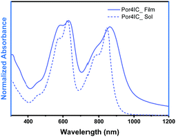
The absorption properties of Por4IC are shown in Fig. 2. Two distinct bands are observed both in solution and thin film with the peak maxima in the former case being located at 626 and 844 nm, while in the latter case at 632 and 862 nm. When going from solution to thin film, the difference between the absorption maxima in the Q band region of Por4IC is only 18 nm. This observation originates from our DFT calculations, as the planar conformation is expected to be minimally distorted by the surrounding environment. However, broadening of the thin-film absorption band (as compared to the well-structured absorption in solution) is indicative of close intermolecular π–π stacking in the solid state. The extinction coefficient in solution was estimated to be an impressive value of 1.1 × 10⁶ M−1 cm−1 at both of the absorption bands (Fig. S8b, ESI†), clearly highlighting the benefit of using Por4IC as a strongly absorbing electron-acceptor material.
 | ||
| Fig. 2 Absorption spectra of Por4IC in solution and as spin-coated thin film. The solution measurements were performed in toluene +1% pyridine. | ||
The frontier orbital energy levels of Por4IC were estimated through cyclic voltammetry. Scheme 1 shows that the LUMO energy level of Por4IC is calculated to be −4.3 eV, while the HOMO and LUMO energy levels of P3HT are −5.1 eV and −2.9 eV, respectively, resulting in a large LUMO–LUMO offset of 1.4 eV between P3HT and Por4IC, which suggests that Por4IC is a promising candidate for trapping electrons. In order to justify this hypothesis, the fabrication of photodetectors followed. As shown previously regarding donor–acceptor interactions in bulk heterojunction blends, when the acceptor is used in a very small amount in a donor–acceptor blend the electron mobility decreases significantly indicating electron trapping.22 However, in higher concentrations the acceptor molecules start to aggregate forming percolation paths for the electrons to travel, and a more balanced charge carrier transport is observed. Hence, for the aspect of this work, and based on the previously published results,7 the concentration of Por4IC is kept as low as 1 wt% in blend with P3HT.
The low Por4IC concentration is justified by the resulting absence of electron transport channels in the active layer and the isolated electron traps formed with Por4IC surrounded by P3HT, while limiting the contact area between Por4IC and the electrodes. In the dark, at reverse bias, the large injection barriers limit the hole injection; the work function of Al is −4.3 eV and the hole injection barriers from the Al electrode onto the HOMOs of P3HT and Por4IC are ca. 0.8 eV and 1.2 eV, respectively. Under light illumination conditions at reverse bias, the channels formed by P3HT will assist in hole transporting in the active layers. The photogenerated electrons will be trapped in the isolated electron traps which are formed by Por4IC surrounded by P3HT. The trapped electrons build up a Coulomb field leading to interfacial bending of the energy levels, especially by those electrons trapped near the Al cathode. This interfacial energy level bending narrows the hole injection barrier for efficient hole tunneling injection from the Al electrode onto the HOMO of P3HT under reverse bias.7 The tunneling injected holes will be transported efficiently along the continuous channels formed by P3HT and collected by the ITO electrode.
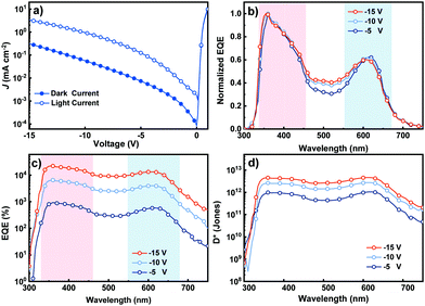
Fig. 3a shows the current density–voltage (J–V) characteristics of the OPDs measured in the dark and under white light illumination conditions at 2 mW cm−2. The current density under light, JL, is at least an order of magnitude higher than the current in the dark, JD, at the same applied reverse bias (see Table 1 for details). This is attributed to the hole tunneling injection assisted by the trapped electrons under light illumination conditions.11 The JL increases with the elevated reverse bias, originating from the enhanced hole tunneling injection from the external circuit and escalated hole transport in the active layer. The JD also increases with the increased reverse bias, as a result of the more injected hole and improved hole transport in the active layer. Devices containing only P3HT in the active layer were also fabricated and characterized in the dark and under 2 mW cm−2 white light illumination conditions, and the J–V curves are shown in Fig. S10, ESI.† The JL of the host only device nearly overlaps with the corresponding JD, indicating no photoresponse. This observation supports that hole tunneling injection has to be assisted by the trapped electrons in Por4IC rather than the intrinsic traps or defects in the P3HT layers.
 | ||
| Fig. 3 (a) J–V curves of the OPDs measured from −5 to −15 V. (b and c) EQE spectra of the OPDs at increasing reverse bias. (d) Detectivity of the PM type OPDs at increasing reverse bias. | ||
| Bias (V) | J L (mA m−2) | J D (mA m−2) | EQE (%) (355 nm) | EQE (%) (610 nm) | D* (Jones) (355 nm) | D* (Jones) (610 nm) |
|---|---|---|---|---|---|---|
| −5 | 1.2 × 10⁻¹ | 7.3 × 10⁻³ | 857 | 578 | 8.8 × 10¹¹ | 1.0 × 10¹² |
| −10 | 9.4 × 10⁻¹ | 5.6 × 10⁻² | 6360 | 4025 | 2.5 × 10¹² | 2.7 × 10¹² |
| −15 | 3.3 | 3.1 × 10⁻¹ | 22![[thin space (1/6-em)]](https://www.rsc.org/images/entities/char_2009.gif) 182 182 |
13![[thin space (1/6-em)]](https://www.rsc.org/images/entities/char_2009.gif) 338 338 |
4.4 × 10¹² | 4.6 × 10¹² |
The EQE spectra of the devices were recorded at different reverse bias values, with the EQE exceeding 100% in all cases indicating the presence of a PM effect induced by trap-assisted hole tunneling injection from the Al electrode to the HOMO level of P3HT.7,23Fig. 3b and c shows the two distinct high-response regions of a well-functioning PM type OPD peaking at about 355 and 610 nm with a dip from 460 to 550 nm. It has been shown previously that the dip originates from a weaker optical field intensity due to the strong absorption of P3HT in this wavelength region leading to less trapped electrons in the dopant close to the Al electrode.7 As seen from Fig. 3b and c, the EQE increased systematically with the increasing reverse bias, and the highest EQE of 22![[thin space (1/6-em)]](https://www.rsc.org/images/entities/char_2009.gif) 182% at 355 nm was achieved at −15 V. The high EQE should be attributed to (i) the enhanced hole tunneling injection from the external circuit due to the energy level tilting and (ii) the enhanced hole transport ability under increased reverse bias. The poor response in a long wavelength range of PM type OPDs is due to the rather low content of Por4IC in blend films.
182% at 355 nm was achieved at −15 V. The high EQE should be attributed to (i) the enhanced hole tunneling injection from the external circuit due to the energy level tilting and (ii) the enhanced hole transport ability under increased reverse bias. The poor response in a long wavelength range of PM type OPDs is due to the rather low content of Por4IC in blend films.
We now move our attention to specific detectivity (D*), a characteristic of the photodetector that is a depiction of its sensitivity and is unaffected by the device area.13 The D* plots of the PM type OPDs were calculated at reverse bias varying from −5 to −15 V as shown in Fig. 3d. The performance systematically improved upon increasing the reverse bias, as calculated using eqn (1):
 | (1) |
The linear dynamic range (LDR) is used to describe the operational light intensity of PM type OPDs and is a very important parameter since it can quantify the ability of photodetectors to capture light at various light intensities.28 The LDR of the PM type OPDs was measured by recording the steady-state photocurrent under 650 nm light illumination conditions at different light intensities varying from 0.05 to 1.52 × 10⁻⁸ W cm−2 at −15 V, as shown in Fig. S11, see the ESI.† The slope of the fitted line was estimated to be 1.01, showing indeed a linearity. The LDR was calculated based on eqn (2):
 | (2) |
In summary, we report the synthesis and characterization of porphyrin molecule Por4IC, which acts as an effective electron trap in blend with P3HT as an active layer in PM type OPDs. The resulting OPDs presented a clear PM effect with an EQE reaching 22![[thin space (1/6-em)]](https://www.rsc.org/images/entities/char_2009.gif) 182% at 355 nm and at −15 V bias. These encouraging results indicate that porphyrin derivatives are promising dopants for PM type OPDs.
182% at 355 nm and at −15 V bias. These encouraging results indicate that porphyrin derivatives are promising dopants for PM type OPDs.
We thank the Swedish Research Council (2016-06146 and 2019-04683), the Swedish Research Council Formas, the Wallenberg Foundation (2017.0186 and 2016.0059) and the Emil Aaltonen Foundation for financial support.
Conflicts of interest
There are no conflicts to declare.Notes and references
- D. Yang and D. Ma, Adv. Opt. Mater., 2019, 7, 1800522 Search PubMed.
- Z. Guo, S. Park, J. Yoon and I. Shin, Chem. Soc. Rev., 2014, 43, 16–29 Search PubMed.
- M. Kielar, O. Dhez, G. Pecastaings, A. Curutchet and L. Hirsch, Sci. Rep., 2016, 6, 39201 Search PubMed.
- M. Hiramoto, T. Imahigashi and M. Yokoyama, Appl. Phys. Lett., 1994, 64, 187–189 Search PubMed.
- J. Miao, F. Zhang, Y. Lin, W. Wang, M. Gao, L. Li, J. Zhang and X. Zhan, Adv. Opt. Mater., 2016, 4, 1711–1717 Search PubMed.
- J. Huang and Y. Yang, Appl. Phys. Lett., 2007, 91, 203505 Search PubMed.
- L. Li, F. Zhang, J. Wang, Q. An, Q. Sun, W. Wang, J. Zhang and F. Teng, Sci. Rep., 2015, 5, 9181 Search PubMed.
- D. K. Neethipathi, H. S. Ryu, M. S. Jang, S. Yoon, K. M. Sim, H. Y. Woo and D. S. Chung, ACS Appl. Mater. Interfaces, 2019, 11, 21211–21217 Search PubMed.
- W. Wang, F. Zhang, M. Du, L. Li, M. Zhang, K. Wang, Y. Wang, B. Hu, Y. Fang and J. Huang, Nano Lett., 2017, 17, 1995–2002 Search PubMed.
- Z. Zhao, J. Wang, J. Miao and F. Zhang, Org. Electron., 2019, 69, 354–360 Search PubMed.
- J. Miao, F. Zhang, M. Du, W. Wang and Y. Fang, Phys. Chem. Chem. Phys., 2017, 19, 14424–14430 Search PubMed.
- L. Li, F. Zhang, J. Wang, Q. An, Q. Sun, W. Wang, J. Zhang and F. Teng, Sci. Rep., 2015, 5, 9181 Search PubMed.
- J. Miao and F. Zhang, Laser Photonics Rev., 2019, 13, 1800204 Search PubMed.
- P. Josse, C. Dalinot, Y. Jiang, S. Dabos-Seignon, J. Roncali, P. Blanchard and C. Cabanetos, J. Mater. Chem. A, 2016, 4, 250–256 Search PubMed.
- S. Li, Z. Zhang, M. Shi, C.-Z. Li and H. Chen, Phys. Chem. Chem. Phys., 2017, 19, 3440–3458 Search PubMed.
- F. Tang, C. Wang, Q. Chen, J. Lai, W. Wang, F. Zhang and L. Chen, Appl. Phys. Lett., 2018, 113, 043303 Search PubMed.
- J. Wang and Q. Zheng, J. Mater. Chem. C, 2019, 7, 1544–1550 Search PubMed.
- M. Mone, S. Tang, P. Murto, B. A. Abdulahi, C. Larsen, J. Wang, W. Mammo, L. Edman and E. Wang, Chem. Mater., 2019, 31, 9721–9728 Search PubMed.
- J. S. Lindsey, in Metalloporphyrins Catalyzed Oxidations, ed. F. Montanari and L. Casella, Springer, Netherlands, Dordrecht, 1994, pp. 49–86, DOI:10.1007/978-94-017-2247-6_2.
- P. Coppo and M. L. Turner, J. Mater. Chem., 2005, 15, 1123–1133 Search PubMed.
- H. Hang, X. Wu, Q. Xu, Y. Chen, H. Li, W. Wang, H. Tong and L. Wang, Dyes Pigm., 2019, 160, 243–251 Search PubMed.
- C. H. Y. Ho, S. H. Cheung, H.-W. Li, K. L. Chiu, Y. Cheng, H. Yin, M. H. Chan, F. So, S.-W. Tsang and S. K. So, Adv. Energy Mater., 2017, 7, 1602360 Search PubMed.
- L. Li, F. Zhang, W. Wang, Y. Fang and J. Huang, Phys. Chem. Chem. Phys., 2015, 17, 30712–30720 Search PubMed.
Footnote |
| † Electronic supplementary information (ESI) available. See DOI: 10.1039/d0cc03933k |
| This journal is © The Royal Society of Chemistry 2020 |

