Pore space partition of a fragile Ag(I)-carboxylate framework via post-synthetic linker insertion†
Dongwook
Kim
 ,
Junmo
Seong
,
Seungwan
Han
,
Seung Bin
Baek
,
Junmo
Seong
,
Seungwan
Han
,
Seung Bin
Baek
 * and
Myoung Soo
Lah
 *
*
Department of Chemistry, Ulsan National Institute of Science and Technology (UNIST), Ulsan 44919, Korea. E-mail: sbbaek@unist.ac.kr; mslah@unist.ac.kr
First published on 19th June 2020
Abstract
The pore space partition approach via post-synthetic linker insertion was used to modulate the porosity of a fragile Ag(I)-carboxylate framework with potentially large pore space. The resulting Ag(I)–MOFs with partitioned pores showed enhanced permanent porosity compared with a nonpartitioned Ag(I)–carboxylate framework.
Metal–organic frameworks (MOFs) are porous crystalline networks primarily composed of coordination bonds between metal ions and organic ligands.1 Their structural diversity represents a significant advantage for many applications based on the intrinsic properties of the constituent metals and functionalized ligands.2 After surveying metal ions for novel porous architectures, silver(I) has become a promising candidate due to its tolerance for a multitude of coordination numbers and geometries.3 Over the past decades, significant efforts have been devoted to preparing porous Ag(I)-based MOFs, but only a few have been investigated for their gas sorption properties4 because of the relatively weak Ag(I)-ligand bonds. These weak bonds often result in framework collapse during the activation process. Therefore, the synthesis of Ag(I)-based MOFs with permanent porosity remains a challenge in the expansion of MOF diversity and the utilization of silver. Recently, a pore space partition (PSP) strategy5 has been developed as a tool for improving the structural stability6 and gas separation abilities of MOFs.7 PSP utilizes the division of large pore spaces into smaller segments by using secondary metal8 or ligand insertion.9 However, most MOFs with partitioned pore space are obtained via one-pot synthesis using all framework building blocks including pore partitioning agents.
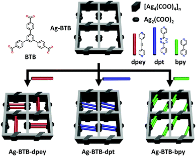
Herein, a rare example of permanently microporous Ag(I)–MOFs achieved by the PSP approach via post-synthetic insertion10 of auxiliary linkers is reported. The parent Ag(I)-carboxylate framework (AgBTB) contains a large one-dimensional (1D) solvent channel. However, AgBTB is fragile and practically nonporous for gas sorption. After partitioning the 1D channel via post-synthetic insertion of dipyridyl linkers, the resulting Ag(I)–MOFs showed improved structural stability upon guest molecule removal. In addition, the framework porosity could be adjusted by the amount and type of linkers added (Scheme 1).
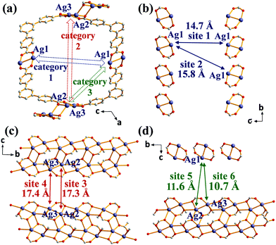
The solvothermal reaction of AgNO3 with 4,4′,4′′-benzene-1,3,5-triyl-tri-benzoic acid (H3BTB) afforded AgBTB crystals. A three-dimensional (3D) coordination network was formed based on a finite [Ag2(COO)2] dinuclear cluster and an infinite [Ag4(COO)4]n 1D ribbon with inorganic nodes and BTB as an organic linker (Fig. 1 and Fig. S1, ESI†). Ag1 of the finite [Ag2(COO)2] secondary building unit (SBU) adopted a square planar geometry with two syn–syn bridging bidentate carboxylate oxygen atoms in a trans-configuration, an Ag atom of an inter-silver bond, and a ligated water molecule. Ag2 and Ag3 of the infinite [Ag4(COO)4]n structure adopted distorted square pyramidal geometries and were interconnected via two carboxylates to form a 1D ribbon along the crystallographic b-axis. AgBTB contained large 1D solvent channels that were 10.4 × 13.0 Å2 in size along the crystallographic b-axis. The total pore volume of AgBTB calculated by PLATON11 was determined to be 3,508 Å3 per unit cell, corresponding to 45.4% of the total unit cell volume. Dye adsorption results show that the AgBTB can absorb dye molecules such as methylene blue and Nile red in ethanol solutions, which suggests the void space of the AgBTB is well preserved in liquid medium (Fig. S2, ESI†). However, the N2 adsorption experiment of activated AgBTB showed no N2 uptake at 77 K. This nonporous behavior is due to pore collapse upon solvent removal from the channel. Interestingly, at least six potential linkage sites of three different categories existed between the Ag atoms in the framework (Fig. 2). Moderate-length linkage sites 1 and 2 of the first category could interconnect in-plane Ag1–Ag1 (∼14.7 Å) and off-plane Ag1–Ag1 (∼15.8 Å), respectively, in the dinuclear Ag clusters facing each other across the 1D channel. However, the longer linkage sites 3 and 4 of the second category interconnect Ag2–Ag2 (∼17.3 Å) and Ag3–Ag3 (∼17.4 Å), respectively, in the tetranuclear Ag clusters. The short linkage sites 5 and 6 of the third category interconnect Ag1–Ag2 (∼11.6 Å) and Ag1–Ag3 (∼10.7 Å), respectively, in the AgBTB framework.
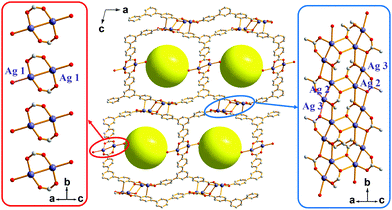 | ||
| Fig. 1 The framework structure of AgBTB with an array of finite [Ag2(COO)2] dinuclear clusters and an infinite [Ag4(COO)4]n 1D ribbon. | ||
Given the above information, the PSP strategy was used to rationally partition the original 1D channel into smaller channels, leading to improved porosity. The PSP was achieved via post-synthetic insertion of carefully selected dipyridyl linkers, 1,2-di(pyridin-4-yl)ethyne (dpey), 3,6-di(pyridin-4-yl)-1,2,4,5-tetrazine (dpt), and 4,4′-bipyridine (bpy), with lengths approximately matching those of the potential linkage sites (Fig. S3, ESI†). Powder X-ray diffraction (PXRD) patterns of the resulting crystals indicated that the dpey linker induced significant reorganization of the AgBTB framework (Fig. S4, ESI†). In contrast, dpt and bpy linkers resulted in only moderate structural changes. Single-crystal structural analyses revealed that the inserted dipyridyl linkers acted as pore-partition agents that interconnect the potential linkage sites in the AgBTB framework (Fig. 3 and Fig. S5–S7, ESI†). The insertion and partitioning modes of the dipyridyl linkers depend on their length. For AgBTB-dpey, since the length of dpey (∼14.6 Å, including two 2.4 Å Ag–N bonds) matches with the potential linkage site 1 (∼14.7 Å), the fit into linkage site 1 was expected. Interestingly, insertions of dpey occurred at the preferred linkage site 1 and at the long linkage site 3 (Ag2–Ag2 pair; Fig. 3b and Fig. S5, ESI†). The original 1D channels (10.4 × 13.0 Å2) along the crystallographic b axis in AgBTB were partitioned by the dpey with horizontal and vertical modes, affording two rectangular 1D solvent channels (types A and B; Fig. 3b). Channel A (3.7 × 11.6 Å2) was generated by the insertion of dpey into linkage site 1, resulting in horizontally partitioned channels. In contrast, the vertically partitioned channel B (3.8 × 9.8 Å2) was created by embedding dpey in linkage site 3. Notably, embedding of the length-mismatched dpey linker at linkage site 3 induced a significant contraction in the unit cell along the c-axis and a ∼5% reduction in AgBTB-dpey unit cell volume compared to that of AgBTB (Table S1, ESI†). It should be noted that the total amount of dpey inserted was ∼75% of the maximum amount. While linkage site 1 was almost fully occupied, only 55% of linkage site 3 was occupied in the single crystal structure. The inserted dpey linker content in the AgBTB-dpey framework was estimated to be ∼74% from the 1H NMR spectrum of the digested sample (Fig. S8, ESI†). This value is in good agreement with the average site occupancy of the dpey linkers in the single crystal structure.
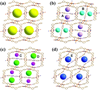 | ||
| Fig. 3 (a) 1D channels of AgBTB and the PSPs through the insertions of the dipyridyl linkers in (b) AgBTB-dpey. (c) AgBTB-dpt, and (d) AgBTB-bpy. | ||
The length of dpt is ∼16.0 Å (with two ∼2.4 Å Ag–N bonds); thus, it was expected that linkage site 2 would be the preferred insertion site. Structural analysis of AgBTB-dpt revealed that post-synthetic insertion of the dpt linker occurred exclusively at linkage site 2 with a site occupancy of 0.74 (Fig. 3c and Fig. S6, ESI†). In contrast to AgBTB-dpey, insertion of the dpt linker into linkage site 2 showed little effect on the unit cell parameters and volume of AgBTB-dpt (Table S1, ESI†). The inserted dpt linker partitioned the original 1D channel into two 1D rectangular channels—3.6 × 11.9 and 5.2 × 12.3 Å2 in size for channels C and D, respectively. The 1H NMR spectrum of digested AgBTB-dpt suggested that the inserted dpt linker content was as high as 63% of the theoretical maximum, slightly lower than the site occupancy of dpt linkers determined via single crystal structure refinement (Fig. S9, ESI†).
The length of bpy (∼12.0 Å, including two 2.4 Å Ag–N bonds) is well-matched with the short-length linkage site 5 (∼11.6 Å). As expected, the insertion of bpy was found to occur only at linkage site 5 with a site occupancy of ∼0.8 (Fig. 3d and Fig. S7, ESI†). The insertion of bpy linkers into all linkage site 5 locations within the 1D channel of AgBTB formed the 1D channel E with dimensions of 5.2 × 12.6 Å2. Similar to dpt insertion, bpy induced no significant rearrangement of the framework. Therefore, the unit cell parameters and volume of the AgBTB-bpy single crystal were very similar to those of AgBTB (Table S1, ESI†). The bpy content estimated from the 1H NMR spectrum of digested AgBTB-bpy was ∼1.06 (Fig. S10, ESI†), indicating that all the linkage sites were fully occupied by bpy linkers, as determined via crystal structure analysis.
It should be noted that the length of the inserted linker is essential for framework rearrangement during linker insertion. As demonstrated, only the dpey linker causes significant contraction of the 1D channel and subsequent reorganization of the framework due to insertion of the length-mismatched linker into linkage site 3 (Table S1 and Fig. S5b, ESI†). In contrast, both dpt and bpy linkers localized to length-matched linkage sites in the framework, exerting negligible effects on the structure reorganization.
AgBTB-dpey, AgBTB-dpt, and AgBTB-bpy prepared in N,N-dimethylformamide (DMF) released substantial amounts of dipyridyl linkers during solvent exchange with methylene chloride. Therefore, AgBTB-dpey(x), AgBTB-dpt(x), and AgBTB-bpy(x) crystals were obtained via immersing AgBTB crystals into x mL of either 1 or 2 mM methylene chloride solution containing the dipyridyl linkers, where x denotes the volume of methylene chloride solution. It should be noted that the amounts of inserted linkers were lower than those of crystals prepared in DMF (Fig. S11, ESI†). Interestingly, the PXRD pattern of AgBTB-dpey(40) differs from that of AgBTB-dpey prepared in DMF (Fig. S4, ESI†). This structural discrepancy may be attributed to the lower site occupancies of the linkage sites 1 and 3 in AgBTB-dpey(40). Because the total amount of the dpey inserted in AgBTB-dpey(40) is much smaller than that of AgBTB-dpey, both linkage sites 1 and 3 on AgBTB-dpey(40) are likely to have lower site occupancies. In particular, the low site occupancy of length-mismatched linkage site 3 did not cause the framework contraction, resulting in a PXRD pattern similar to that of the parent framework AgBTB. Meanwhile, the AgBTB-dpt(40) and AgBTB-bpy(40) PXRD patterns are similar to those prepared in DMF. For the gas sorption experiments, activated AgBTB-dpey(x)a, AgBTB-dpt(x)a, and AgBTB-bpy(x)a were prepared in vacuum at 298 K for 1 day to minimize pore collapse.
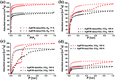
Activated AgBTB (AgBTB-a) showed no N2 uptake at 77 K and minor CO2 uptake (up to ∼10 cm3 g−1) at 195 K (Fig. S12, ESI†). Meanwhile, the N2 uptake of AgBTB-dpey(10)a with ∼25% site occupancy was ∼98 cm3 g−1 at relative pressure P/P0 = 1, reaching ∼137 cm3 g−1 for AgBTB-dpey(40)a with ∼48% site occupancy (Fig. 4a). The BET specific surface areas were calculated as 503 and 342 m2 g−1 for AgBTB-dpey(40)a and AgBTB-dpey(10)a, respectively. At 195 K, the CO2 isotherms exhibited stepwise adsorption and hysteresis during desorption, which becomes evident for AgBTB-dpey(40)a (Fig. 4b). The CO2 adsorption amounts at 1 bar increased from ∼118 cm3 g−1 for AgBTB-dpey(10)a to ∼160 cm3 g−1 for AgBTB-dpey(40)a. However, at 273 and 298 K the CO2 isotherms exhibited neither stepwise adsorption nor hysteresis (Fig. S13, ESI†). The stepwise adsorption is likely due to stability differences between partitioned channels A and B in the AgBTB-dpey framework. Highly populated dpey linkers in channel A effectively prevented pore collapse during activation to a larger extent than the less populated dpey linkers in channel B. The stepwise adsorption observed at ∼0.6 bar is likely a result of the recovery of the partially collapsed pore upon CO2 adsorption. The N2 and CO2 adsorption results demonstrated that the PSP approach accomplished via post-synthetic dpey insertion enhanced the structural stability of AgBTB-dpey(x)a over that of AgBTB.
For AgBTB-dpt(x)a, neither AgBTB-dpt(10)a nor AgBTB-dpt(40)a showed any N2 uptake at 77 K (Fig. S14, ESI†). Even though the site occupancies of the dpt linkers, ∼35% and ∼48% for AgBTB-dpt(10)a and AgBTB-dpt(40)a, respectively (Fig. S11, ESI†), are comparable to those of the corresponding AgBTB-dpey(x)a moieties, the frameworks were not sufficiently stable upon activation. The site 2 linkage between the off-plane Ag1–Ag1 pair across the 1D channel resulted in inefficient partitioning of the 1D channel, leading to pore collapse in AgBTB-dpt(x) during activation. However, at 195 K AgBTB-dpt(x) exhibited stepwise CO2 adsorption behavior with hysteresis, which is pronounced for AgBTB-dpt(40)a (Fig. 4c). The CO2 adsorption at 1 bar increased from ∼130 cm3 g−1 for AgBTB-dpt(10)a to ∼160 cm3 g−1 for AgBTB-dpt(40)a. This stepwise adsorption can be attributed to the degree of recovery of the collapsed channels. The smaller channel C (3.6 × 11.9 Å2) is likely restored at lower CO2 pressures, followed by the recovery of the larger channel D (5.2 × 12.3 Å2) at higher CO2 pressures. At 273 and 298 K, the recovery of both channels is ineffective, and CO2 uptakes were ∼35 and 17 cm3 g−1 at 273 and 298 K, respectively, for AgBTB-dpt(40)a (Fig. S15, ESI†).
Similarly, the bpy linkers in AgBTB-bpy(10)a and AgBTB-bpy(40)a occupied 22% to 36% of the potential linkage sites, showing no N2 uptake at 77 K (Fig. S16, ESI†). The CO2 adsorption of AgBTB-bpy(10)a measured at 195 K exhibited a type I isotherm curve, with total CO2 uptake of ∼40 cm3 g−1 (Fig. 4d). The total CO2 uptake for AgBTB-bpy(40)a reached ∼65 cm3 g−1 due to the increased linkage site occupancy of the bpy linkers. Stepwise adsorption was observed along with hysteresis, which can be rationalized using the same argument discussed earlier. The presence of the bpy linker in the framework of AgBTB-bpy(40)a allowed for initial CO2 adsorption up to ∼0.35 bar. At pressure of >0.35 bar, recovery of the collapsed solvent channels can occur. At 273 and 298 K, gradually increasing CO2 uptake is observed with increasing amounts of bpy linkers. The maximum CO2 uptakes for AgBTB-bpy(40)a were ∼15 and 10 cm3 g−1 at 273 and 298 K, respectively (Fig. S17, ESI†).
In summary, rare examples of permanently porous Ag(I)-based MOFs were prepared herein using the PSP approach via post-synthetic insertion of auxiliary dipyridyl linkers. The dipyridyl linkers determined the partitioning modes of the original 1D channel in the parent AgBTB framework and enhanced framework stability. Consequently, permanent porosities of the prepared MOFs (AgBTB-dpey, AgBTB-dpt, and AgBTB-bpy) were achieved. The stability and porosity of the frameworks could be adjusted by the amount and type of linkers added.
This work was supported by NRF (2016R1A5A1009405) through the National Research Foundation of Korea. The authors gratefully acknowledge the Pohang Accelerator Laboratory (PAL) for the use of the synchrotron 2D (SMC) beamline (2019-2nd-2D-013 and 2019-3rd-2D-044).
Conflicts of interest
There are no conflicts to declare.Notes and references
- (a) N. W. Ockwig, O. Delgado-Friedrichs, M. O’Keeffe and O. M. Yaghi, Acc. Chem. Res., 2005, 38, 176 CrossRef CAS PubMed; (b) S. R. Batten, N. R. Champness, X.-M. Chen, J. Garcia-Martinez, S. Kitagawa, L. Öhrström, M. O’Keeffe, M. Paik Suh and J. Reedijk, Pure Appl. Chem., 2013, 85, 1715 CAS.
- H. Furukawa, K. E. Cordova, M. O’Keeffe and O. M. Yaghi, Science, 2013, 341, 1230444 CrossRef PubMed.
- (a) L.-Y. Du, W.-J. Shi, L. Hou, Y.-Y. Wang, Q.-Z. Shi and Z. Zhu, Inorg. Chem., 2013, 52, 14018 CrossRef CAS; (b) M. A. Haja, C. B. Aakeröy and J. Desper, New J. Chem., 2013, 37, 204 RSC; (c) B. S. Fox, M. K. Beyer and V. E. Bondybey, J. Am. Chem. Soc., 2002, 124, 13613 CrossRef CAS PubMed.
- (a) C. R. Murdock and D. M. Jenkins, J. Am. Chem. Soc., 2014, 136, 10983 CrossRef CAS PubMed; (b) M. Handke, H. Weber, M. Lange, J. Möllmer, J. Lincke, R. Gläser, R. Staudt and K. Krautscheid, Inorg. Chem., 2014, 53, 7599 CrossRef CAS PubMed; (c) I. Bassanetti, F. Mezzadri, A. Comotti, P. Sozzani, M. Gennari, G. Calestani and L. Marchiò, J. Am. Chem. Soc., 2012, 134, 9142 CrossRef CAS PubMed.
- Q.-G. Zhai, X. Bu, X. Zhao, D.-S. Li and P. Feng, Acc. Chem. Res., 2017, 50, 407 CrossRef CAS PubMed.
- Y.-P. Wu, J.-W. Tian, S. Liu, B. Li, J. Zhao, L.-F. Ma, D.-S. Li, Y.-Q. Lan and X. Bu, Angew. Chem., Int. Ed., 2019, 58, 12185 CrossRef CAS PubMed.
- (a) S.-T. Zhang, J. T. Bu, Y. Li, T. Wu, F. Zuo, P. Feng and X. Bu, J. Am. Chem. Soc., 2010, 132, 17062 CrossRef PubMed; (b) Y.-X. Tan, Y.-P. He and J. Zhang, Chem. Commun., 2011, 47, 10647 RSC; (c) Y. Ling, M. Deng, Z. Chen, B. Xia, X. Liu, Y. Yang, Y. Zhou and L. Weng, Chem. Commun., 2013, 49, 78 RSC; (d) Y. Ye, Z. Ma, R.-B. Lin, R. Krishna, W. Zhou, Q. Lin, Z. Zhang, S. Xiang and B. Chen, J. Am. Chem. Soc., 2019, 141, 4130 CrossRef CAS; (e) H. Yang, Y. Wang, R. Krishna, X. Jia, Y. Wang, A. N. Hong, C. Dang, H. E. Castillo, X. Bu and P. Feng, J. Am. Chem. Soc., 2020, 142, 2222 CrossRef CAS.
- (a) Z. Lu, J. Zhang, J. Duan, L. Du and C. Hang, J. Mater. Chem. A, 2017, 5, 17287 RSC; (b) H.-X. Zhang, M. Liu, G. Xu, L. Liu and J. Zhang, Chem. Commun., 2016, 52, 3552 RSC; (c) X. Zhao, X. Bu, E. T. Nguyen, Q.-G. Zhai, C. Mao and P. Feng, J. Am. Chem. Soc., 2016, 138, 15102 CrossRef CAS.
- (a) X. Zhao, X. Bu, Q.-G. Zhai, H. Tran and P. Feng, J. Am. Chem. Soc., 2015, 137, 1396 CrossRef CAS; (b) S.-T. Zheng, J. J. Bu, T. Wu, C. Chou, P. Feng and X. Bu, Angew. Chem., Int. Ed., 2011, 50, 8858 CrossRef CAS PubMed; (c) X. Wang, W.-Y. Gao, J. Luan, L. Wojtas and S. Ma, Chem. Commun., 2016, 52, 1971 RSC.
- (a) S. M. Cohen, J. Am. Chem. Soc., 2017, 139, 2855 CrossRef CAS PubMed; (b) P. Müller, F. M. Wisser, V. Bon, R. Grünker, I. Senkovska and S. Kaskel, Chem. Mater., 2015, 27, 2460 CrossRef; (c) S. Yuan, Y.-P. Chen, J.-S. Qin, W. Lu, L. Zou, Q. Zhang, X. Wang, X. Sun and H.-C. Zhou, J. Am. Chem. Soc., 2016, 138, 8912 CrossRef CAS PubMed; (d) C.-X. Chen, Z. Wei, J.-J. Jiang, Y.-Z. Fan, S.-P. Zheng, C.-C. Cao, Y.-H. Li, D. Fenske and C.-Y. Su, Angew. Chem., Int. Ed., 2016, 55, 9932 CrossRef CAS PubMed; (e) H. Kim, D. Kim, D. Moon, Y. N. Choi, S. B. Baek and M. S. Lah, Chem. Sci., 2019, 10, 5801 RSC.
- A. L. Spek, Acta Crystallogr., Sect. C: Struct. Chem., 2015, 71, 9 CrossRef CAS PubMed.
Footnote |
| † Electronic supplementary information (ESI) available: Details of experimental procedures, crystallographic information, supplementary tables, additional experimental data and figures. CCDC 2000395–2000398. For ESI and crystallographic data in CIF or other electronic format see DOI: 10.1039/d0cc03472j |
| This journal is © The Royal Society of Chemistry 2020 |

