
 Open Access Article
 This Open Access Article is licensed under a
 Creative Commons Attribution 3.0 Unported Licence
Determination of membrane capacitance and cytoplasm conductivity by simultaneous electrorotation†
Shikiho
Kawai
ab,
Masato
Suzuki
 *a,
Satoshi
Arimoto
b,
Tsuguhiro
Korenaga
b and
Tomoyuki
Yasukawa
*a
*a,
Satoshi
Arimoto
b,
Tsuguhiro
Korenaga
b and
Tomoyuki
Yasukawa
*a
aDepartment of Material Science, University of Hyogo, 3-2-1, Kouto, Kamigori, Ako, Hyogo, 678-1297, Japan. E-mail: yasu@sci.u-hyogo.ac.jp; suzuki@sci.u-hyogo.ac.jp
bTechnology Innovation Division, Panasonic Corporation, 3-1-1, Yagumo-naka-machi, Moriguchi, Osaka, 570-8501, Japan
First published on 28th May 2020
Abstract
Membrane capacitances and cytoplasm conductivities of hematopoietic cells were investigated by simultaneous electrorotation (ROT) systems of multiple cells. Simultaneous ROT was achieved by the rotation of electric fields in grid arrays formed with three-dimensional interdigitated array (3D-IDA) electrodes that can be easily fabricated using two substrates with IDA electrodes. When AC signals were applied to four microband electrodes with a 90° phase difference to each electrode, cells dispersed randomly in the 3D-IDA device started to rotate and moved to the center of each grid. Multiple cells were simultaneously rotated at the center of grids without friction from contact with other cells and substrates. The averages and variance of ROT rates of cells at each frequency can be measured during a single operation of the device within 5 min, resulting in the acquisition of ROT spectra. Membrane capacitances and cytoplasm conductivities of hematopoietic cells (K562 cells, Jurkat cells, and THP-1 cells) were determined by fitting ROT spectra obtained experimentally to the curves calculated theoretically. The values determined by using the simultaneous ROT systems well coincided with the values reported previously. The membrane capacitances and cytoplasm conductivities of WEHI-231 cells were firstly determined to be 8.89 ± 0.25 mF m−2 and 0.28 ± 0.03 S m−1, respectively. Furthermore, the difference of the ROT rates based on the difference of the electric properties of cells was applied to discriminate the types of cells. The acquisition of rotation rates of multiple cells within a single operation makes the statistical analysis extremely profitable for determining the electrical properties of cells.
1. Introduction
The electrical properties of cells (i.e. membrane capacitance and cytoplasm conductivity) have been studied to understand the complex physiological states of cells1–3 and used as markers for determining types of leukemia,4 differentiated cells5–7 and cells infected by bacteria.8 The patch-clamp method has traditionally been applied to determine these properties,9,10 however it is invasive, laborious and time-consuming owing to the insertion of a sharpened glass capillary into a single cell. Impedance measurements have been developed to determine the electrical properties as a non-invasive technique. In microfluidic impedance cytometry, the impedance was measured by applying an AC voltage to microelectrodes arranged in parallel in a microfluidic channel, when cells passed over electrodes.11,12 However, a single cell must be positioned between microelectrodes to obtain the impedance spectra of single cells by applying different frequencies and the dynamic changes of electric properties for single cells. Recently, nanofluidic techniques have been applied to analyze single-cells without laborious and time-consuming procedures.13 Particularly, the extended nano-channel was expected to monitor the viability of single-cells by measuring the electrical resistance.14,15Electrorotation (ROT) has also been utilized to characterize the electrical properties of single cells.16,17 A torque is induced to cells by the electrostatic interaction between the constant rotating electric field generated by the configuration of multi-electrodes and the dipole moment formed by the difference in electrical polarizabilities of cells and media in the electric field. In the ROT techniques, quadrupole electrodes with the gaps patterned in a crisscross on the substrate were conventionally used to induce a rotating electric field at the center of the quadrupole electrodes by applying sine waves with a 90° phase difference to each other. The electrical properties of cells were identified by fitting the ROT spectra that are rotation rates obtained as a function of applied frequencies to the theoretically calculated spectra. So far, the ROT techniques have been applied to study eukaryotic parasite transmission stages.18 However, a relatively long experimental period was required because several single cells must be repeatedly arranged at a center of quadrupole electrodes.
In our group, a device consisting of two interdigitated microband array (IDA) electrodes with a three-dimensional (3D) arrangement was previously developed to be applied for the simultaneous ROT of silica microrods.19 When sine waves with a 90° phase difference were applied to four microband electrodes on upper and lower substrates, microrods moved to the grids surrounded by four microbands to form the array and started to rotate simultaneously. Most recently, the simultaneous rotation of multiple single cells was reported to characterize the electrical properties of cells.20,21 The quadrupole array of vertical electrodes arranged symmetrically was used to rotate single cells in parallel at the center of the cages surrounded by four electrodes. However, the fabrication processes of vertical electrodes is substantially complex compared to those of planar electrodes by conventional lithography. Furthermore, the individual connection of each electrode prevents the increase of the number of cages for simultaneous ROT of cells. The rotation of cells in the center of the rotating electric field is extremely important to obtain accurate ROT spectra. Thus, the assistance by laser tweezers,22 the combination of negative dielectrophoresis (n-DEP) and ROT,23–25 and the use of octopoles which consist of two quadrupole electrodes placed on the upper and lower substrates have been studied to arrange the cells at the centers.26 However, these methods have been limited to single cell rotation.
In this study, we applied a 3D-IDA device to rotate single cells simultaneously at the center of grids formed by four microband electrodes. The thousand cells dispersed randomly moved to the center of grids and rotated at each position due to the 3D symmetric arrangement of the quadrupole array. The device has the added advantages of simplicity and ease of use. The device can be fabricated by the opposed arrangement of two IDA electrodes which were prepared by conventional lithography. The connection of only four electrodes is required. The acquisition of rotation rates of multiple cells with a single operation of the device makes the statistical analysis extremely profitable for determining the electrical properties of cells.
2. Materials and methods
2.1 Theory of electrorotation and data analysis
ROT is a phenomenon associated with the rotation of dielectric particles under a uniform rotation of an electric field. The rotational torque is generated by the interaction of a rotating electric field with a dipole moment induced on particles. The rotating electric field is generally formed by applying four sinusoidal signals with phase quadrature to quadruple electrodes. Under a uniform rotating electric field of strength E, a rotation rate Ω of a cell is given by:27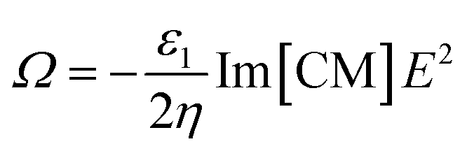 | (1) |
In eqn (1), ε1 and η are the absolute permittivity and the dynamic viscosity of the suspension medium, respectively, the operator Im […] is the imaginary part of the complex parameter inside brackets and CM is the Clausius–Mossotti factor. The CM factor is given by
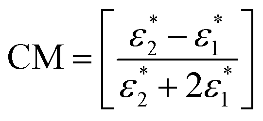 | (2) |
 and
and  represent the complex permittivities of a cell and a medium, respectively and are given by:
 | (3) |
 , ε and σ are the permittivity and conductivity, respectively, and ω is the angular frequency (ω = 2πf, f is the frequency) of the applied electric signal. A single-shell model has been extensively applied to estimate the dielectric properties of cells with complex elements such as conductivities and permittivities of the membrane and cytoplasm of cells (Fig. S1†). In this model, a cell with a single layer was replaced by an equivalent homogeneous particle. The CM factor of a cell with a radius R is expressed below by adapting a single-shell model (see Appendix A in the ESI†).
 | (4) |
Here, τm = CmR/σi, τi = εi/σi, τ1 = ε1/σ1, and τ′m = CmR/σ1, where Cm is the membrane capacitance. The membrane capacitance is defined as εm/δ, where, εm and δ are the permittivity of the medium and the membrane thickness.
The dielectric parameters of cells, which are membrane capacitance and cytoplasm conductivity, were determined by comparing ROT rates obtained experimentally at various frequencies with rates calculated theoretically from eqn (1) and (4). We adopted a least-squares fit by minimizing the sum of the squared deviations (the residual sum) between experimentally obtained rotation rates (Rexp) and calculated rates (Rest),

We assumed that the relative permittivity of the cytoplasm of different types of cells εi is 100 according to previous studies4,23 because of there being no effect on the rotation rate in the frequency range below 10 MHz.27 The relative permittivity ( , ε0 is the permittivity of the vacuum electric constant), conductivity and viscosity of the ROT solution used in this study were 80.0, 0.36 S m−1, and 1.00 mPa s, respectively.
2.2. Cell preparation
Chronic myelogenous leukemia (K562), human T cell leukemia (Jurkat) and a human cell line derived from monocytic leukemia (THP-1) were obtained from the cell bank of RIKEN BioResource Center. These cells were grown in RPMI 1640 medium (Sigma-Aldrich, St Louis, MO) supplemented with 10% fetal bovine serum (FBS; Life Technologies, Carlsbad, CA) and 1% penicillin–streptomycin (Wako Pure Chemical Industries, Osaka, Japan). Mouse B cell line (WEHI-231) obtained from The European Collection of Authenticated Cell Culture (ECACC). WEHI-231 was grown in DMEM medium (Sigma-Aldrich) supplemented with 10% fetal bovine serum, 1% penicillin–streptomycin and 50 μM 2-mercaptoethanol (Wako). These cells were cultured under standard cell culture conditions, with 5% CO2 at 37 °C.2.3. Experiments for the electrorotation
IDA electrodes with 40 microbands of indium-tin oxide (ITO) were purchased from ATSUGI MICRO CO., LTD (Fig. S2(A) and (B)†). Each microband electrode was 2.2 mm in length and 20 μm in width, with 30 μm gaps between microband electrodes. The area for ROT was defined as 2 × 2 mm2 by covering with a transparent insulator (2 μm thickness) except for the area for ROT. Fig. 1(A) illustrates the configuration of the 3D-IDA device. A substrate with IDA electrodes (Fig. S2(A)†) was overlaid on another substrate with IDA (Fig. S2(B)†) by an orthogonal arrangement via a double-sided adhesive film with 30 μm in thickness (Nitto Denko Co., Osaka, Japan) used as a spacer, resulting in the formation of the 3D-IDA configuration with 1521 grids. Moreover, an inlet and outlet (4 × 4 × 1 mm) were fabricated at both ends of the microfluidic channel, respectively (Fig. S2(C)†).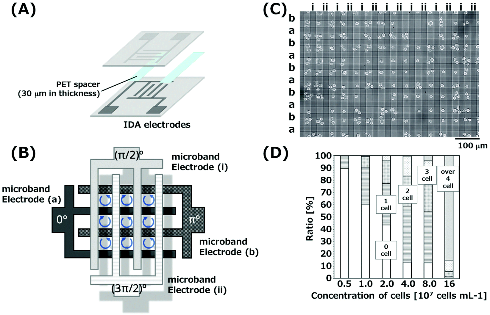 | ||
| Fig. 1 (A) Schematic illustration of the 3D-IDA device. Two substrates with IDA electrodes were orthogonally superimposed. The suspension of cells was introduced in spaces between the upper and lower substrates for the simultaneous ROT of cells. (B) Illustration of the array of grids surrounded by four microband electrodes. (C) K562 cells rotating at the center of grids. (D) Ratio of the number of cells trapped in single grids. | ||
The 3D-IDA device was treated with an oxygen plasma for 5 min at 100 W to enhance the hydrophilicity of the device for injecting cell suspensions. The solution containing 30 mg mL−1 bovine serum albumin (Wako Pure Chemical Industries) was added to the device for 2 hours at 4 °C to prevent nonspecific adsorption of cells. Cells were centrifuged at room temperature at 1000 rpm for 5 min and washed in a ROT solution with the conductivity of 360 mS m−1 (75% (v/v) of 300 mM mannitol and 25% (v/v) of RPMI 1640 medium). The final concentration was adjusted to 5.0 × 10⁶–1.6 × 10⁸ cells per mL for ROT measurements. After washing the device with the ROT solution, an aliquot of cell suspension was introduced to the device. An AC voltage (5Vpp, 100–1000 kHz) was then applied with a 90° phase difference to each microband electrode by using a function generator (Active Technologies, Ferrara, Italy) to generate rotating electric fields in the grids. The rotation of cells was observed using an inverted microscopy (Nikon Co., Tokyo, Japan) equipped with a CMOS camera (ARGO Co., Osaka, Japan). The rotation rates were manually calculated from trajectories of characteristic points on surfaces of rotating cells which were extracted from movies.
2.4. Immunocytochemistry
A CD7 antigen expressed on the membrane of Jurkat cells was immunohistologically stained by anti-CD7 antibody labeled with phycoerythrin (PE) (clone 8H8.1, Beckman Coulter, Inc. Brea CA). Cells (1.0 × 10⁶–1.0 × 10⁷ cells per mL) were incubated in a culture medium containing 715 ng mL−1 anti-CD7 antibody for 60 min in the dark at 4 °C, and then washed twice with ROT solution by centrifugation at 1000 rpm for 5 min.3. Results and discussion
3.1. Simultaneous electrorotation of cells by 3D-IDA devices
K562 cells were simultaneously electrorotated by 3D-IDA devices. Fig. 1(B) illustrates the grid array of the 3D-IDA device. We applied an AC signal to the microband electrode (a), while AC signals with a phase delay of π/2, π and 3π/2 were applied to electrodes (i), (b) and (ii), respectively, to exert rotational electric fields in each grid. When AC signals (700 kHz, 5Vpp) were applied, K562 cells dispersed randomly in the 3D-IDA device started to rotate and moved to the center of each grid (Fig. 1(C) and Movie S1†). Electric fields rotated to a clockwise direction in grids which were surrounded by microband electrodes (a), (i), (b) and (ii) in a counterclockwise direction. In contrast, the rotation direction of electric fields is opposite in the other half grids, because the direction of arranged electrodes is opposite. Thus, the rotation direction of cells trapped in the neighboring grids is opposite. It is noted that the rotation direction of cells in grids was opposite compared to that of electric fields. It may be due to the effective polarization of water molecules with higher permittivity at the cell surface under the present experimental conditions.K562 cells experience negative dielectrophoresis (n-DEP) in the electric field generated by applying AC voltages to microband electrodes at the frequency of 700 kHz in the medium with the conductivity of 360 mS m−1 (Fig. S3†). In n-DEP, cells move to the relatively weak electric field region by receiving the repulsive force from the relatively strong electric field.28 Relatively weak regions were formed at the center of grids due to the strong electric field generated vertically at the intersections formed by the upper and lower microband electrodes with the shortest distance, resulting in the cells moving to the center of grids and rotating at those positions. The formation of the relative weak electric field regions at the center of grids was also revealed by the simulation of the electric field reported from our group previously.19 Moreover, cells rotating in the grids could not contact the bottom substrates by n-DEP. This is significantly advantageous due to the removal of the effect of the friction between cells and bottom substrates. We reported the formation of cell aggregates by gathering cells with n-DEP using a similar device previously.29 Cell aggregations which were applied to an AC voltage of 20Vpp for 45 min maintained the esterase activity and grew to spheroids. In contrast, an AC voltage of 5Vpp for 5 min was only applied to cells to obtain ROT spectra in the present study. Thus, the cells used in the experiments would maintain viability.
We evaluated the ratio of grids occupied by a single cell. Fig. 1(C) shows the image of cells rotating in the grids, when the cell suspension with the concentration of 4.0 × 10⁷ cells per mL was injected. 45% of grids were occupied by single cells. Grids with two or three cells and without cells were also observed due to the stochastic movement of cells randomly arranged before applying AC signals. Images of the rotation cells with different initial concentrations of cell suspensions are shown in Fig. S4.† The concentration of the cell suspension corresponding to single cell occupation in all grids was theoretically calculated to be 1.3 × 10⁷ cells per mL. When the cell suspensions with a low concentration compared to that calculated theoretically were injected, grids were occupied by single cells, however, empty grids were prominent (Fig. S4†). Fig. 1(D) shows the ratio of the number of trapped cells in single grids. The number of grids occupied with cells increased with increasing initial concentration, while the number of grids occupied with multiple cells also increased. When the concentrations of cell suspensions were 2.0–8.0 × 10⁷ cells per mL, the ratio of grids with single cells was found to be 30–45%. However, the concentrations of cells calculated from the number of cells in images and the volume in the device were reduced to less than 30% of the initial concentration over 8.0 × 10⁷ cells per mL. In addition, the concentrations calculated from images for initial concentrations of 2.0 × 10⁷ and 4.0 × 10⁷ cells per mL corresponded to 50–60%. The decrease may be due to the clogging of cells at the inlets. These results suggested that the highest ratio of single cell rotation in single grids is obtained at the initial concentrations of 2.0–4.0 × 10⁷ cells per mL, which are slightly higher than the theoretical concentration. Thus, we could obtain the rotation rates of 450–680 cells (40–60 cells in single images) simultaneously.
We also investigated rotation manners of cells trapped in the grids. The single cells trapped in the grids rotated on their own axis at the center of grids. However, when multiple cells were trapped in the grids, cells moved around the center of grids, as they rotated on their own axis. Fig. 2(A) shows trajectories of x and y axes (dx and dy) of a characteristic point on the surface of a single cell trapped in a grid. The rotation rate of a K562 cell trapped in the grid containing only that single cell was estimated and found to be 8.03 radian per s. The amplitude of dx and dy was independent of the period. Thus, the result suggests that the cell rotates around the center of the cell. Fig. 2(B) shows the distribution of rotation rates of K562 cells. The average rotation rate of 51 cells which were trapped in grids with a single cell per grid and rotated with the frequency of 700 kHz was estimated to be 8.53 radian per s with the standard deviation of 1.58 radian per s. The average and variation of the rotation rate of single cells can be easily determined from a single operation of this device without the repeated arrangement of cells to the center and support by external forces. In contrast, rates of cells trapped in a grid containing multiple cells were significantly slow compared to those of a single cell in a grid. The decrease may result from the cell rotation around the center of grids such as revolution and the contact of rotating cells together in the grids. Therefore, the ROT rates of cells should be estimated by the cells trapped in the grids occupied by single cells.
 | ||
| Fig. 2 (A) Trajectories of x and y axes (dx and dy) of a characteristic point on the surface of a single cell trapped in a grid. (B) Distribution of rotation rates of K562 cells. | ||
3.2 Determination of dielectric properties of cells
ROT rates were plotted as a function of applied frequencies to obtain the ROT spectra. Fig. 3(A)–(D) show the spectra for four types of cells. AC signals with the frequencies from 100 kHz to 1 MHz were applied to the electrodes. All types of cells trapped in the grids in a single cell manner rotated at the center of grids, because they experienced n-DEP in this frequency region. The rotation rate of K562 cells increased with the increment of applied frequency up to 600 kHz, and then decreased (Fig. 3(A)). The dashed curves in Fig. 3(A)–(D) were theoretically calculated by a least-squares fit to experimental plots with eqn (1) and (4). The spectra experimentally obtained corresponded well with the curves obtained theoretically. The relationship of the determined membrane capacitance and cytoplasm conductivity, and cell radius is represented in Fig. 3(E) as a three-dimensional plot. The values determined from four different cells are plotted at different positions in Fig. 3(E). The result thus suggests that the four types of cells individually possess characteristic values. The values for four types of cells are listed in Table 1. The determined membrane capacitances and cytoplasm conductivities for K562, Jurkat and THP-1 cells were close to those reported previously, summarized in Table S1.† The dispersion of rotation rates of cells arose from the variability of the electrical properties of cells, because no significant difference was observed in the rotation rate of silica microrods (Polysciences, Inc., Warrington, PA) with the same length used as a standard sample. The measurement error in the system was evaluated by using the rate of microrods with the average length of 19.9 μm (Fig. S6(C)†). After microrods were introduced into the 3D-IDA device, the AC signal (600 kHz, 10Vpp) was applied to rotate microrods by ROT. The rotation rates of microrods trapped in grids with a single microrod per grid were similar (15.6 ± 0.23 (±S.E.) radian per s). Thus, the measurement error in the system is negligible. The present system is advantageous as repeated operations after exchanging cells in the area for the ROT are not needed. The time required to obtain the data for rotation rates of 50 cells with 10 different frequencies is only 5 min. Therefore, the simultaneous ROT of multiple single cells by using the 3D-IDA device allows for the determination of the electrical properties of cells simply and rapidly with a single operation.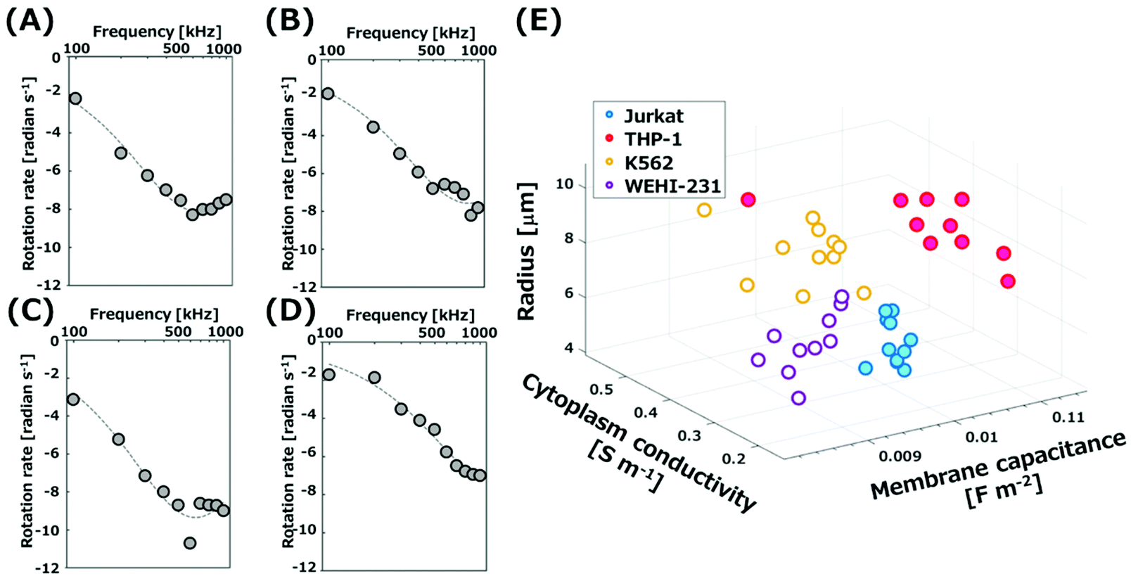 | ||
| Fig. 3 ROT spectra of (A) K562 cells, (B) Jurkat cells, (C) THP-1 cells, and (D) WEHI-231 cells. (E) A scattering plot of the dielectric parameters and cell radius of hematopoietic cells. | ||
| Cell types | Radius [μm] | Membrane capacitance | Conductivity of cytoplasm [S m−1] |
|---|---|---|---|
| Jurkat | 6.02 ± 0.15 | 9.82 ± 0.08 | 0.25 ± 0.01 |
| THP-1 | 8.22 ± 0.25 | 11.0 ± 0.14 | 0.37 ± 0.02 |
| K562 | 9.17 ± 0.29 | 9.16 ± 0.07 | 0.32 ± 0.02 |
| WEHI-231 | 6.08 ± 0.25 | 8.76 ± 0.34 | 0.29 ± 0.03 |
The WEHI-231 cell is a mouse immature B-cell widely used as a model to study the development and the activation of B-cells,30,31 while the dielectric properties have not been investigated. We determined, for the first time, the membrane capacitance and the cytoplasm conductivity of WEHI-231 cells in the present 3D-IDA system to be 8.89 ± 0.25 (±standard error; S.E.) mF m−2 and 0.28 ± 0.03 (±S.E.) S m−1, respectively. Both values are smaller than those for the other three types of cells. The spectrum for WEHI-231 cells (Fig. 3(D)) is shifted due to the decrease of the rotation rate and increase of the frequency compared to those of the other three (Fig. 3(A)–(C)). From eqn (1) and (4), we easily found the spectrum to shift to a higher frequency with decreasing membrane capacitance, and to show a lower rate with decreasing cytoplasm conductivity. The standard error of the rotation rate for WEHI-231 cells was larger than those of the other three. This may be due to the presence of two groups with the different expression patterns of surface antigens in the population of WEHI-231 cells.32–34 Moreover, the membrane capacitance of THP-1 (human monocytic cell line) is large compared to those of Jurkat cells (human T cell leukemia) and WEHI-231 cells (Mouse B cell line). The large membrane capacitance of monocytes could be attributed to the large surface area of membranes in the presence of a large number of well-developed and broad-based ruffles on the membrane of monocytes.4,35
3.3 Discrimination of types of cells by electrorotation
The difference of the ROT rates based on the difference of the electrical properties of cells was applied to discriminate the types of cells. It is difficult to discriminate Jurkat cells and THP-1 cells by an optical microscope because of the similarity of shapes that are spherical with about 15 μm in diameter (Fig. S5†). We performed a discrimination of Jurkat cells and THP-1 cells with simultaneous ROT by the 3D-IDA device. CD7 expressed on the membrane surface of Jurkat cells was labeled with anti-CD7 antibody conjugated with PE to identify Jurkat cells from the mixture. There was no cross-reaction to THP-1 cells for anti-CD 7 antibody (Fig. S5†). After the mixture of labeled Jurkat cells and THP-1 cells was injected into the 3D-IDA device, an AC signal (600 kHz, 5Vpp) was applied to rotate cells by ROT. Fig. 4(A) shows the optical, fluorescence and merged images of cells rotating at the center of grids. The red fluorescence and its position allow for the discrimination of types of cells. Jurkat cells and THP-1 cells rotating in grids containing a single cell were labeled with the alphabet “J” and “T” in the merged image, respectively. Fig. 4(B) shows the distribution of rotation rates of Jurkat cells with and without PE-label, and THP-1 cells. The average rotation rate of 61 Jurkat cells and 38 THP-1 rotated with the frequency of 600 kHz was estimated to be 6.46 ± 0.16 (±S.E.) radian per s and 9.92 ± 0.27 (±S.E.) radian per s, respectively. There was a statistical difference between the rotation rate of labeled Jurkat cells and THP-1 cells (p < 0.005). The rotation rate of unlabeled Jurkat cells was also investigated and found to be 6.45 ± 0.21 (±S.E.) radian per s (n = 19). No statistical difference between labeled and unlabeled Jurkat cells was observed. Consequently, this result suggests that the binding of antibody to the surface antigen expressed on the cell membrane does not affect the values of dielectric properties of cells. According to the results, the discrimination of cell types in cell populations could be possible by the simultaneous ROT of cells with a single and simple operation process without the labelling of cells.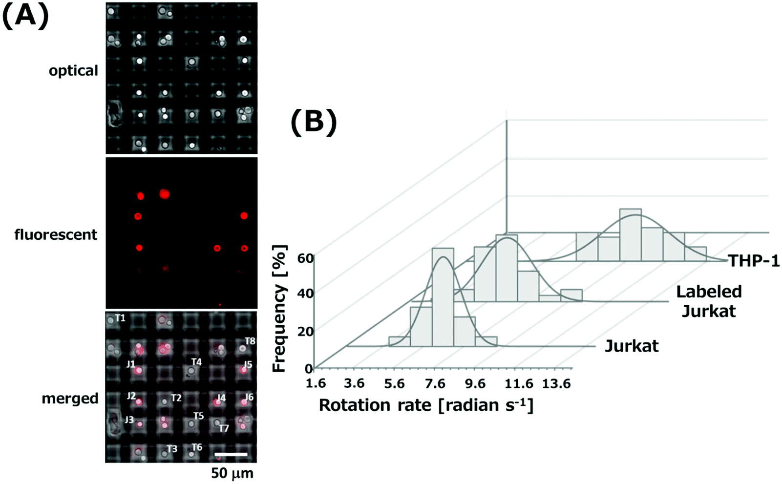 | ||
| Fig. 4 (A) Optical, fluorescence and merged images of the mixture of Jurkat cells and THP-1 cells which rotated in the grids by applying AC signals with the frequency of 600 kHz and the voltage of 5Vpp. (B) Distribution of rotation rates of THP-1 cells and labeled and unlabeled Jurkat cells. | ||
4. Conclusions
The simultaneous ROT of cells was done using 3D-IDA devices to determine the membrane capacitances and cytoplasm conductivities of four types of cells with a single operation of each device. Over 1500 grids surrounded by four microband electrodes for the ROT of cells can be easily fabricated by using two IDA electrodes as upper and lower substrates. The rotational electric fields can be formed by applying AC signals with a 90° phase difference between each microband electrode, resulting in the simultaneous rotation of 450–680 cells with a single cell in each grid. By fitting the rotation spectra obtained experimentally to the theoretical curves, we determined the membrane capacitances and cytoplasm conductivities of Jurkat cells, THP-1 cells and K562 cells which coincided with the values reported previously. Furthermore, the membrane capacitance and cytoplasm conductivity of WEHI-231 cells were firstly determined by this method and found to be 8.89 ± 0.25 (±S.E.) mF m−2 and 0.28 ± 0.03 (±S.E.) S m−1, respectively. The difference of the ROT rates based on the difference between the electrical properties of cells was applied to discriminate the types of cells. The acquisition of rotation rates of multiple cells in a single operation of the device makes the statistical analysis extremely profitable for determining the electrical properties of cells.Conflicts of interest
The authors declare no competing financial interest.Acknowledgements
S. K. and M. S. performed experiments and analyzed experimental data. T. Y., S. A., and T. K. conceived the project. S. K., M. S., and T. Y. wrote the paper. This work was supported by JSPS KAKENHI Grant Numbers 18H05993 and 19K05548 to MS and 18K19006 to TY.References
- M. Mansor and M. Ahmad, Int. J. Mol. Sci., 2015, 16, 12686–12712 CrossRef CAS PubMed.
- E. A. Henslee, P. Crosby, S. J. Kitcatt, J. S. W. Parry, A. Bernardini, R. G. Abdallat, G. Braun, H. O. Fatoyinbo, E. J. Harrison, R. S. Edgar, K. F. Hoettges, A. B. Reddy, R. I. Jabr, M. von Schantz, J. S. O'Neill and F. H. Labeed, Nat. Commun., 2017, 8, 1978 CrossRef PubMed.
- Q. Wang, A.-A. D. Jones, J. A. Gralnick, L. Lin and C. R. Buie, Sci. Adv., 2019, 5, eaat5664 CrossRef PubMed.
- J. Yang, Y. Huang, X. Wang, X.-B. Wang, F. F. Becker and P. R. C. Gascoyne, Biophys. J., 1999, 76, 3307–3314 CrossRef CAS PubMed.
- X. B. Wang, Y. Huang, P. R. C. Gascoyne, F. F. Becker, R. Hölzel and R. Pethig, Biochim. Biophys. Acta, Biomembr., 1994, 1193, 330–344 CrossRef CAS.
- M. Xavier, M. C. de Andrés, D. Spencer, R. O. C. Oreffo and H. Morgan, J. R. Soc., Interface, 2017, 14, 20170233 CrossRef PubMed.
- A. R. Yale, J. L. Nourse, K. R. Lee, S. N. Ahmed, J. Arulmoli, A. Y. L. Jiang, L. P. McDonnell, G. A. Botten, A. P. Lee, E. S. Monuki, M. Demetriou and L. A. Flanagan, Stem Cell Rep., 2018, 11, 869–882 CrossRef CAS PubMed.
- C. Honrado, L. Ciuffreda, D. Spencer, L. Ranford-Cartwright and H. Morgan, J. R. Soc., Interface, 2018, 15, 20180416 CrossRef PubMed.
- B. Rituper, A. Guček, J. Jorgačevski, A. Flašker, M. Kreft and R. Zorec, Nat. Protoc., 2013, 8, 1169–1183 CrossRef PubMed.
- V. Bandmann, A. S. Mirsanaye, J. Schäfer, G. Thiel, T. Holstein and M. Mikosch-Wersching, Sci. Rep., 2019, 9, 12999 CrossRef PubMed.
- J. Chen, C. Xue, Y. Zhao, D. Chen, M. H. Wu and J. Wang, Int. J. Mol. Sci., 2015, 16, 9804–9830 CrossRef CAS PubMed.
- C. Petchakup, K. Li and H. Hou, Micromachines, 2017, 8, 87 CrossRef.
- L. Lin, Q. Chen and J. Sun, TrAC, Trends Anal. Chem., 2018, 99, 66–74 CrossRef CAS.
- L. Lin, K. Mawatari, K. Morikawa and T. Kitamori, Anal. Sci., 2016, 32, 75–78 CrossRef CAS PubMed.
- L. Lin, K. Mawatari, K. Morikawa, Y. Pihosh, A. Yoshizaki and T. Kitamori, Analyst, 2017, 142, 1689–1696 RSC.
- J. Gimsa, P. Marszalek, U. Loewe and T. Y. Tsong, Biophys. J., 1991, 60, 749–760 CrossRef CAS PubMed.
- A. W. Griffith and J. M. Cooper, Anal. Chem., 1998, 70, 2607–2612 CrossRef CAS PubMed.
- C. Dalton, A. D. Goater, J. P. H. Burt and H. V. Smith, J. Appl. Microbiol., 2004, 96, 24–32 CrossRef CAS PubMed.
- K. Ino, A. Ishida, K. Y. Inoue, M. Suzuki, M. Koide, T. Yasukawa, H. Shiku and T. Matsue, Sens. Actuators, B, 2011, 153, 468–473 CrossRef CAS.
- K. Keim, M. Z. Rashed, S. C. Kilchenmann, A. Delattre, A. F. Gonçalves, P. Éry and C. Guiducci, Electrophoresis, 2019, 40, 1830–1838 CrossRef CAS PubMed.
- M. Eguchi, K. Horio, F. Kuroki, H. Imasato and T. Yamakawa, in World Automation Congress Proceedings, IEEE Computer Society, 2018, vol. 2018, pp. 136–139.
- C. Reichle, T. Schnelle, T. Müller, T. Leya and G. Fuhr, Biochim. Biophys. Acta, Bioenerg., 2000, 1459, 218–229 CrossRef CAS.
- S.-I. Han, Y.-D. Joo and K.-H. Han, Analyst, 2013, 138, 1529 RSC.
- Y. C. Kung, T. Man, K. W. Huang, W. Chong, J. King and P. Y. Chiou, in 2017 IEEE 12th International Conference on Nano/Micro Engineered and Molecular Systems, NEMS 2017, Institute of Electrical and Electronics Engineers Inc., 2017, pp. 355–359.
- Y. Okamoto, T. Tsuchiya, C. Moslonka, Y. S. Lin, S. Tsang, F. Marty, A. Mizushima, C. L. Sun, H. Y. Wang, A. Tixier-Mita, O. Francais, B. Le Pioufle and Y. Mita, in 2019 20th International Conference on Solid-State Sensors, Actuators and Microsystems and Eurosensors XXXIII, TRANSDUCERS 2019 and EUROSENSORS XXXIII, Institute of Electrical and Electronics Engineers Inc., 2019, pp. 213–216.
- C. Reichle, T. Müller, T. Schnelle and G. Fuhr, J. Phys. D: Appl. Phys., 1999, 32, 2128–2135 CrossRef CAS.
- L. Huang, P. Zhao and W. Wang, Lab Chip, 2018, 18, 2359–2368 RSC.
- M. Suzuki, T. Yasukawa, H. Shiku and T. Matsue, Biosens. Bioelectron., 2008, 24, 1043–1047 CrossRef CAS PubMed.
- T. Yasukawa, A. Morishima, M. Suzuki, J. Yoshioka, K. Yoshimoto and F. Mizutani, Anal. Sci., 2019, 35, 895–901 CrossRef CAS PubMed.
- T. Tsubata, J. Wu and T. Honjo, Nature, 1993, 364, 645–648 CrossRef CAS PubMed.
- S. Machtaler, M. Dang-Lawson, K. Choi, C. Jang, C. C. Naus and L. Matsuuchi, J. Cell Sci., 2011, 124, 2611–2621 CrossRef CAS PubMed.
- L. L. Lanier and N. L. Warner, J. Immunol., 1981, 126, 626–631 CAS.
- A. R. Gottschalk and J. Quintans, Immunol. Cell Biol., 1995, 73, 8–16 CrossRef CAS PubMed.
- F. J. X. Spillmann, G. Beck-Engeser, M. Wabl and J. G. Monroe, J. Immunol., 2007, 179, 6395–6402 CrossRef CAS PubMed.
- H. DeLeon III, A. Kuang, F. Rugama and T. Eubanks, J. Tumor Res., 2017, 3, 123 Search PubMed.
Footnote |
| † Electronic supplementary information (ESI) available. See DOI: 10.1039/d0an00100g |
| This journal is © The Royal Society of Chemistry 2020 |