 Open Access Article
Dynamic magnetic properties and spin pumping in polymer-assisted-deposited La0.92MnO3 thin films
Hailin
Wang
 ,
Alberto
Pomar
 *,
Sergi
Martín-Rio
 ,
Carlos
Frontera
 ,
Narcis
Mestres
 and
Benjamín
Martínez

Instituto de Ciencia de Materiales de Barcelona, ICMAB-CSIC, Campus de la UAB, 08193 Bellaterra, Spain. E-mail: apomar@icmab.es; Tel: +34 935801853
First published on 17th September 2019
Abstract
Complex oxide thin films grown by using chemical methods are of strong interest because of their low-cost, environment friendly fabrication and easy scalability. However, their introduction in spintronic applications or magnetic devices is still scarce mainly because of concerns regarding their interfacial quality. Here, we report on the preparation by polymer-assisted-deposition (PAD) of epitaxial La0.92MnO3 (LMO) thin films. We demonstrate that ferromagnetic conducting LMO thin films with smooth surfaces (rms ∼ 0.2 nm) can be prepared by PAD. By means of temperature-dependent broadband ferromagnetic resonance (FMR), we show that the LMO film exhibits a four-fold in-plane anisotropy, with [110] being the easy in-plane axis, compatible with strain release from the rhombohedral bulk phase. It has also been found that the isotropic Gilbert damping, α, determined from the broadening of the FMR linewidth, does not show a relevant extrinsic contribution and it exhibits an intraband-like temperature dependence, i.e. it increases as temperature decreases. By capping LMO thin films with a 10 nm thick Pt layer deposited ex situ, damping is substantially enhanced, from a value at 150 K of αLMO ∼ 1 × 10⁻² for the bare LMO film to αLMO+Pt ∼ 2.5 × 10⁻² for the Pt capped film. This strong increase of magnetic damping is indicative of the transfer of spin momentum from LMO to the Pt layer by spin pumping. Our results demostrate that LMO films grown by PAD may be used as efficient spin source systems in heterostructures for spintronic devices.
1 Introduction
The utilization of transition metal oxides in spintronic applications relies on the availability of high-quality thin films that may be helpful in the ever-increasing demands of miniaturization and reduced power consumption. Among the different promising technologies, devices based on the spin transfer torque effect are very appealing due to the possibility of manipulating spin configurations in an efficient way with low power consumption.1 Thus, a noticeable effort has been devoted to studying the magnetization switching processes, crucial to spin torque phenomena and, in particular, to understanding and controling magnetic damping.2,3 In general, low magnetic damping constants may be achieved in transition metal oxide films, either in insulating materials as yttrium iron garnet4 or in half-metallic compounds as La2/3Sr1/3MnO3.5 In the last case, the main drawback arises from the important extrinsic contribution to damping associated with the scattering of conduction electrons by the two magnon mechanism.6 This extrinsic damping is enhanced by the presence of surface/interface roughness or magnetic inhomogenity originating from the defect landscape of the film. Nevertheless, a tough tuning of the growth conditions allows obtaining intrinsic damping values in the order of 10−3 for films grown by using physical methods (pulsed laser deposition, sputtering or molecular beam epitaxy).2 These low Gilbert damping values open the possibility to use half-metallic manganite-based oxides to generate pure spin currents by, for example, spin pumping into a non magnetic metal. Although few investigations have been made, there are already several promising results proving this approach.7–10The strong activity in the field has boosted a fast improvement in the quality of grown thin films. Although high-vacuum methods, such as molecular beam epitaxy,11 RF sputtering12 and pulsed laser deposition,13–15 offer unquestionable advantages for the growth of metal oxide thin films like high crystal quality, precise control of composition and thickness at atomic-scale even for several unit cell thick films, more affordable alternatives are desirable. Generally speaking, chemical deposition techniques offer the ability to grow over large areas at low cost and the versatility to easily tune stoichiometry in complex oxides makes chemical deposition techniques very appealing. In particular, polymer assisted deposition (PAD) has appeared as a competitive route for environment friendly approaches as it is based on the deposition of cationic aqueous solutions.16 It is also worth noting that since the aqueous PAD precursor solutions are largely stable, they enable setting a metal library easily to be mixed afterwards to obtain finely compositionally controlled complex oxides. Moreover, although larger processing times may appear as a drawback, the slow growth conditions of PAD close to thermodynamic equilibrium conditions are adequate for the epitaxial growth of ternary and complex oxides as has already been demonstrated for a large variety of oxide films.17,18 Since the energy balance involved during the growth process is quite delicate, chemical growth methods may lead to a defect landscape different from that generated by using vacuum techniques, resulting in the modification of the physical properties of the films, as for example, magnetic anisotropy.19 In spite of their importance, the dynamic magnetic properties of chemically grown films remain an open and unexplored topic.
The main aim of this work is to study the magnetic anisotropy and damping of oxide thin films grown by PAD and to demonstrate that they are suitable for spintronic applications. For this, we have selected the ferromagnetic-metallic La0.92MnO3. LaMnO3, the parent compound of the colossal magnetoresistance family of manganite perovskites, has recently regained new attention as an oxide catalyst for fuel cells and metal–air batteries,20 and as an electrode material for supercapacitors,21 as well as due to its unexpected ferromagnetic behavior in thin films.22–24 Although bulk stoichiometric LaMnO3 is a Mott insulator and an A-type antiferromagnet (AF), in thin film form, its properties may be tuned into a ferromagnetic (FM) state due to the structural strain induced by the substrate25,26 or by introducing ion vacancies (both in La and Mn sites) in the material.27–29 However, LaMnO3 is a complex system where it is very difficult to disentangle the effects of strain, oxygenation and cation vacancies on the magnetic state. On one hand, theoretical studies indicated that the FM behavior in LaMnO3 thin films originates from the strain-induced orbital ordering26 and this mechanism was invoked to explain the tuning between AF and FM states in stoichiometric LaMnO3 thin films prepared under different growth oxygen pressures.25 On the other hand, the dependence of magnetic properties on film thickness is still puzzling as, while an increase of saturation magnetization and transition temperature with increasing thickness was reported for films grown on SrTiO3,30 the opposite seems to occur for films grown on LaAlO3 substrates.31 It is worth noting that, in the case of stoichiometric samples, the material exhibits an insulating character in both the AF and the FM states.25 However, in the presence of cationic vacancies, to preserve charge neutrality, a mixed Mn3+ and Mn4+ valence state appears. This mixed valence state promotes the appearance of double exchange interaction via oxygen atoms driving the system into a ferromagnetic and metallic state.28 As an example, 8% of La site vacancies in LaMnO3 creates 24% of holes at the Mn sites leading to a robust ferromagnetic ordering. This is the amount of holes present in La0.76Ca0.24MnO3, for example, although the smaller cationic disorder in La0.92MnO3 makes its electronic conductivity much larger, and its Curie temperature increases up to values close to Tc = 300 K making it interesting for spintronic applications. In this work, we have studied, by broadband ferromagnetic resonance, the magnetodynamic properties of ferromagnetic La0.92MnO3 thin films prepared by PAD. The interest of this research is twofold. First, from a materials point of view, it is crucial to investigate if the continuous progress in the quality of PAD films may overcome the challenging difficulties of roughness and homogeneity control even for properties highly dependent on defect structure as magnetic damping. Second, from a physics point of view, an attempt is made to clarify the mechanisms controlling the magnetodynamic behavior, which will be fundamental for future prospects.
2 Thin film growth and characterization
The La0.92MnO3 (LMO) thin films studied in this work were grown by polymer-assisted-deposition (PAD) on (001)-SrTiO3 (STO) single-crystal substrates. Individual solutions of the different metal ions were prepared by dissolving the corresponding La and Mn nitrates in water with ethylenediaminetetraacetic acid (EDTA, 1![[thin space (1/6-em)]](https://www.rsc.org/images/entities/char_2009.gif) :
:![[thin space (1/6-em)]](https://www.rsc.org/images/entities/char_2009.gif) 1 molar ratio) and polyethylenimine (PEI), Sigma Aldrich, Ref 408727, with an average molecular weight of 25
1 molar ratio) and polyethylenimine (PEI), Sigma Aldrich, Ref 408727, with an average molecular weight of 25![[thin space (1/6-em)]](https://www.rsc.org/images/entities/char_2009.gif) 000 (1
000 (1![[thin space (1/6-em)]](https://www.rsc.org/images/entities/char_2009.gif) :
:![[thin space (1/6-em)]](https://www.rsc.org/images/entities/char_2009.gif) 1 mass ratio to EDTA). Each individual solution was filtrated using Amicon filtration units (10 kDa), and retained portions were analyzed by Inductively Coupled Plasma (ICP) spectroscopy (Optima 4300 DV™ ICP-OES PerkinElmer). The solutions were mixed according to the desired La
1 mass ratio to EDTA). Each individual solution was filtrated using Amicon filtration units (10 kDa), and retained portions were analyzed by Inductively Coupled Plasma (ICP) spectroscopy (Optima 4300 DV™ ICP-OES PerkinElmer). The solutions were mixed according to the desired La![[thin space (1/6-em)]](https://www.rsc.org/images/entities/char_2009.gif) :
:![[thin space (1/6-em)]](https://www.rsc.org/images/entities/char_2009.gif) Mn 0.92
Mn 0.92![[thin space (1/6-em)]](https://www.rsc.org/images/entities/char_2009.gif) :
:![[thin space (1/6-em)]](https://www.rsc.org/images/entities/char_2009.gif) 1 final stoichiometry ratio and spin coated on top of 5 × 5 mm2 (001)-SrTiO3 (STO) substrates purchased from Crystec GmbH, Germany. The as-received substrates were chemically etched and thermally treated to make them TiO2-terminated with atomically flat terraces.32 After the deposition of the polymeric layer, it was annealed in a horizontal tube furnace under oxygen flow at 950 °C for 30 min. The results discussed in this paper correspond to the layers of LMO of 10 nm as determined by X-ray reflectometry. They were obtained using solutions with a total cation concentration of 139 mM and a rate of 5000 rpm for 90 seconds during spinning.
1 final stoichiometry ratio and spin coated on top of 5 × 5 mm2 (001)-SrTiO3 (STO) substrates purchased from Crystec GmbH, Germany. The as-received substrates were chemically etched and thermally treated to make them TiO2-terminated with atomically flat terraces.32 After the deposition of the polymeric layer, it was annealed in a horizontal tube furnace under oxygen flow at 950 °C for 30 min. The results discussed in this paper correspond to the layers of LMO of 10 nm as determined by X-ray reflectometry. They were obtained using solutions with a total cation concentration of 139 mM and a rate of 5000 rpm for 90 seconds during spinning.
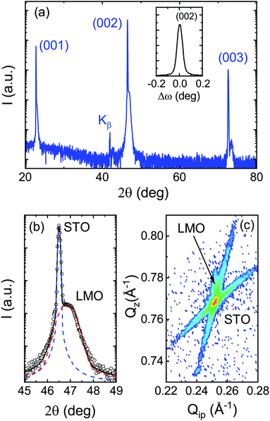
Systematic θ–2θ X-ray measurements as shown in Fig. 1(a) demonstrate that LMO thin films are in a single phase with no signatures of reflections other than the standard pseudocubic (00l) ones. High crystallinity and excellent out-of-plane orientation of the film were evidenced by the low values, less than 0.1°, of the full-width at half-maximum (FWHM) of the rocking curves around the (002) reflection peak (see the inset in Fig. 1(a)). In Fig. 1(b), we show the detail of the θ–2θ scan around the (002) diffraction peak where the deconvolution of the substrate and film peaks is indicated by the corresponding lines. Fitting of the (00l) peak positions leads to a pseudocubic out-of-plane parameter of a⊥ ∼ 3.87 Å. The strain state of the LMO films was studied by using reciprocal space maps around (−103)STO reflections, as shown in Fig. 1(c). As thin film reflection is very close to the substrate one, in this case, to increase the signal-to-noise ratio, thicker films (∼20 nm) were used. The in-plane lattice parameter of the LMO film, a‖, matches that of the substrate one, i.e., a‖ = 3.905 Å. With these a‖ and a⊥ values, a rough estimation of pseudocubic volume can be calculated leading to Vpc = a‖2a⊥ ∼ 59.0 Å3. The above obtained values may be compared with the reported bulk ones. It is known that the crystal structure of LaMnO3 perovskite strongly depends on oxygen content. In particular, for La-deficient La0.92MnOx samples, a transition has been reported from the orthorhombic Pnma structure for x = 2.88 to a rhombohedral R![[3 with combining macron]](https://www.rsc.org/images/entities/char_0033_0304.gif) c one for x = 2.98.33 Concomitant to this structural evolution, unit cell volume is reduced from Vort = 61.0 Å3 for Pnma to Vrh = 58.9 Å3 for R
c one for x = 2.98.33 Concomitant to this structural evolution, unit cell volume is reduced from Vort = 61.0 Å3 for Pnma to Vrh = 58.9 Å3 for R![[3 with combining macron]](https://www.rsc.org/images/entities/char_0033_0304.gif) c. Furthermore, rhombohedral lattice parameters arh = 5.477 Å and αrh = 60.614° correspond to a pseudocubic matching distance of
c. Furthermore, rhombohedral lattice parameters arh = 5.477 Å and αrh = 60.614° correspond to a pseudocubic matching distance of  leading to a +0.4% tensile mismatch by the STO substrate.34 Thus, our experimental results suggest a strain accommodation mainly through elastic mechanisms from the rhombohedral phase.35
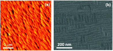
Morphological characteristics of the LMO film surfaces were analyzed via Atomic Force Microscopy (AFM) in tapping mode. Under optimal growth conditions, films develop an atomically flat surface that mimics the terrace-step morphology of the surface of the underlying STO substrate, as shown in Fig. 2(a). Quantitative analysis of a 5 μm × 5 μm image indicates a flat surface with rms ∼ 0.25 nm, i.e., less than one unit cell. Further confirmation of the high quality of the surface morphology and microstructure of the films was obtained via scanning electron microscopy (SEM). Fig. 2(b) shows a typical SEM image of a 10 nm thick LMO film. In this image, taken at a small tilting angle of 2°, we may observe the occurrence of alternating parallel stripes with bright and dark contrast. Such stripes are almost aligned with the [100] edges of the substrate and they form domains of ∼25 nm wide. As reported previously for Sr doped LMO films, they are typical of an ordered twin structure in rhombohedral films grown under tensile strain and they are the result of smooth strain accommodation during film growth.36
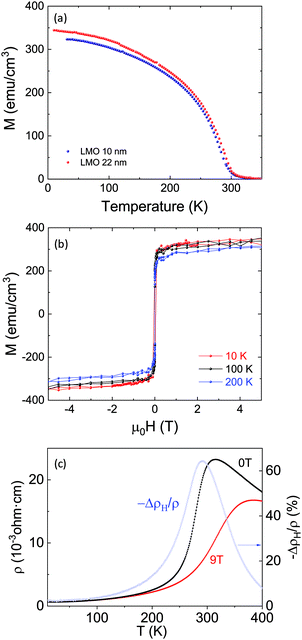
Static magnetic properties were measured using a Quantum Design SQUID magnetometer with the external magnetic field applied parallel to the substrate plane. Field-cooled temperature dependence of magnetization, Fig. 3(a), as well as isothermal hysteresis loops, Fig. 3(b), were measured. Note that magnetic measurements have been corrected using the diamagnetic contribution of the STO substrate. LMO films are strongly ferromagnetic and no significant differences were observed as a function of thickness for samples in the range of 10–25 nm, as evidenced in Fig. 3(a). Hysteresis loops recorded between 10 K and 200 K shown in Fig. 3(b) reflect the reduction of the saturation and remnant magnetization expected from the temperature dependence of magnetization presented in Fig. 3(a). On the other hand, coercive fields are very small (less than 15 mT at 100 K) and very similar for all the studied samples irrespective of their thickness, which suggests that in the thickness range analysed (10–20 nm) the microstructure of the samples is very similar. As mentioned above, although stoichiometric LaMnO3 is an antiferromagnetic insulator, the presence of La vacancies leads to a mixed valence state of the Mn cation (Mn3+–Mn4+) that promotes the strong ferromagnetic interaction mediated by the standard double exchange mechanism. The obtained values of saturation magnetization M(5 K) ∼ 330 emu cm−3 (corresponding to ∼2.1 μB f.u.−1) and transition temperature, Tc ∼ 290 K, are slightly lower than expected for La0.92MnO3 composition. Two main mechanisms may be invoked to explain the reduction of the saturation magnetization in thin films with respect to the bulk value. First, it is known that at the interface with the substrate, a non magnetic dead layer may be formed due to the relaxation of biaxial stress during growth.35 In this case, the measured magnetization values are affected by a wrong estimation of the real magnetic thickness. However, this dead layer tends to be of the order of a few unit cells and it cannot explain the strong deviation from the expected magnetization value in our films.35 A second possibility is linked to the oxygen content of the film. In mixed valence manganites, where ferromagnetism is mediated by double-exchange interactions, saturation magnetization is controlled by the ratio Mn3+/Mn4+. A significant amount of oxygen vacancies implies a lower concentration of Mn4+ cations and thus a reduction of magnetization. This is the usual scenario in oxygen-deficient films. However, in LaMnO3, a reduction of magnetization was also observed in overoxidized bulk samples.28 Here, growth under strong oxidizing conditions promotes the creation of cation vacancies (as interstitial sites are not available for excess oxygen) and Mn4+-rich clusters may be formed. These clusters enhance antiferromagnetic correlations between Mn4+ cations and thus, full ferromagnetism is not achieved. So, we cannot disregard either of these mechanisms to explain our results shown in Fig. 3(a). In the standard double exchange picture, a metal–insulator transition (MIT) takes place, concomitant to the magnetic transition. We have measured the transport properties of the films, i.e., temperature dependence of their electrical resistivity and magnetoresistance, defined as ΔρH/ρ = (ρH − ρ0)/ρ0 by using a standard 4-probe van der Pauw configuration. The results are plotted in Fig. 3(c). Films exhibited a well defined metal-to-insulator transition with TMI = 280 K defined as the inflexion point in the ρ(T) curve. Residual resistance was found to be ρ10K = 6 × 10⁻⁴ Ω cm. This value is lower than that reported for La-deficient LMO films grown by using physical methods.29 At an applied magnetic field of 9 T, the maximum value of magnetoresistance was found to be 60% at 280 K, i.e., close to the transition temperature. As a summary, static magnetic and magnetotransport measurements confirmed that LMO films grown by the PAD route exhibit low disorder and strong ferromagnetic character driven by a double-exchange mechanism.
3 Magnetodynamic properties and discussion
The dynamic magnetic properties of LMO thin films as a function of temperature were studied by using a ferromagnetic resonance spectrometer (FMR) made of a broadband coplanar waveguide (NanOsc), inserted in a Physical Properties Measurements System (PPMS by Quantum Design). Measurements were performed at constant temperature using a sweeping external field at several fixed microwave frequencies (between 2 GHz and 17 GHz). Two main in-plane orientations were studied, either with the field applied along the main substrate edges, i.e., μ0H‖[100]STO, or at 45° of the edges, i.e., μ0H‖[110]STO. Fig. 4(a) shows typical FMR spectra obtained at 9 GHz and 100 K for both orientations. Note that, for a better comparison, measured signals (proportional to the first derivative of the microwave absorption intensity) have been renormalized to their respective maximum values. Each FMR spectrum may be fitted to the derivative of the sum of symmetric and antisymmetric Lorentzian components as previously suggested.37 Solid lines in Fig. 4(a) correspond to the respective fitting curves. From these fittings, accurate values of the resonant field, Hres, and of the half-width at half-maximum linewidth, ΔH, are obtained. In transition metal oxide thin films, the presence of a small secondary resonant mode attributed to the presence of sample inhomogeneity is usually reported (secondary phase or regions with slightly different Curie temperature or magnetization that resonate at a different frequency/field).38 In our case, in the whole studied temperature range, no signature of another resonant mode was observed.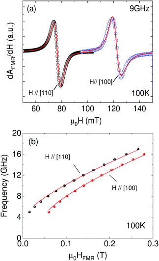 | ||
| Fig. 4 (a) Ferromagnetic resonance spectra as a function of applied field for the two main in-plane orientations, i.e., [110] and [100], taken at 100 K and 9 GHz. Solid lines represent the best fittings to the sum of symmetric and antisymmetric Lorentz line shapes as explained in the main text. (b) Frequency dependence of the resonant field at 100 K for the two main in-plane orientations. Solid lines correspond to the best simultaneous fit of both experimental data to eqn (2) and (3) in the main text. | ||
The noticeable difference of the resonance field for both configurations just reflects a different saturation magnetization in each direction, i.e., in-plane magnetocrystalline anisotropy. In this case, [110] represents the in-plane easy axis (lower resonant field). Such in-plane anisotropy has been previously reported in other manganite based thin films39 and it is believed to be a direct consequence of the highly epitaxial growth of materials with lower symmetry (orthorhombic/rhombohedral) onto cubic substrates as [110] is the in-plane projection of the [111] direction that, in manganite based perovskites, is the bulk easy axis.40 It is worth noting that in the present case, no measurable differences in the FMR response between [100] and [010] directions have been observed. This is in agreement with previous results in thin films grown by chemical methods.19 The absence of any extra in-plane uniaxial anisotropy, which, on the contrary, is usually observed in thin films grown by physical methods,41 has been attributed to the different relaxation mechanisms involved during epitaxial growth using diverse techniques. This leads to different octahedral rotation patterns in the films to accommodate the stress and, as a consequence, to change orbital overlap and the magnetocrystalline anisotropy.
In the presence of in-plane anisotropy, the frequency dependence of the resonant field is no longer described by the simple Kittel relationship and symmetry considerations need to be taken into account. For epitaxial thin films, a good approach is to consider a tetragonal symmetry, i.e., by assuming [100] and [010] directions to be equivalent. In this case, the resonance condition may be written as41
 | (1) |
For the main in-plane directions, eqn (1) easily simplifies and it may be written for H‖[100], ϕ = 0°, as
 | (2) |
 | (3) |
Although eqn (2) and (3) are overparametrized, simultaneous and self-consistent fitting for both orientations allows obtaining reliable values of H4ip. Its relation with temperature is plotted in Fig. 5(a). In this plot, error bars arise by averaging the data from several samples and taking into account the uncertainty in the fitting. First, we may see that H4ip is negative, reflecting that indeed [110] is the in-plane easy axis. Secondly, it monotonously decreases when approaching the transition temperature. At 10 K, H4ip is of the order of −100 mT. By using MS values obtained from static SQUID measurements, this H4ip value leads to an anisotropic constant of K4ip(10 K) = −1.8 × 10⁴ erg cm−3, which is similar to the reported values for manganite-based thin films.19,39,42,43 Anisotropic fields are expected to decay with temperature faster than saturation magnetization. In general, a power law dependence of the type K(T)/K(T0) = [MS(T)/MS(T0)]l is expected, where K(T0) and MS(T0) are, respectively, the anisotropic field and magnetization at low temperature while l depends on the order of the anisotropy constant.41 The inset in Fig. 5(a) shows the experimental dependence of K4ip(T)/K4ip(T0) as a function of MS(T)/MS(T0) with T0 = 10 K. Experimental data are properly described by a power-law behavior that can be fitted by an exponent l = 6 (solid line).
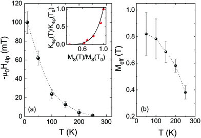 | ||
| Fig. 5 (a) Temperature dependence of the fourfold in-plane anisotropy field, H4ip, extracted from fits as shown in Fig. 4. The inset shows the power-law dependence of the normalized in-plane anisotropy constant K4ip(T)/K4ip(T0) as a function of normalized magnetization MS(T)/MS(T0). (b) Temperature dependence of Meff. Error bars correspond to the uncertainty in the fit procedure and average over different samples. Dotted lines are guides for the eyes. | ||
On the other hand, γ and Meff are closely interdependent during the fitting process and a wide interval of values leads to equally good fittings. Nevertheless, best fits have been obtained for γ/2π = gμB/h ∼ 29.5 GHz T−1 implying that the gyromagnetic factor, g ∼ 2.1, is slightly higher than the spin-only value of 2 usually observed in manganites and it seems to suggest a small contribution from orbital angular momentum. With the above assumptions, the temperature dependence of Meff was obtained and it is plotted in Fig. 5(b) where error bars reflect uncertainty in the fitting parameters. By using the MS values obtained from SQUID measurements, it easily follows that only negative values of K⊥ are able to fit the experimental data. As mentioned above, K⊥ includes not only any uniaxial magnetocrystalline anisotropy but also shape anisotropy and both are indistinguishable. A summary of the main magnetic parameters extracted from static and dynamic magnetic measurements is presented in Table 1.
| Parameter | LMO/STO |
|---|---|
| Gyromagnetic ratio, γ/2π | 29.5 GHz T−1 |
| Gilbert damping, α at 150 K | 1 × 10⁻² |
| Inhomogeneous line-width, ΔH0 at 150 K | <1 mT |
| In-plane anisotropic constant, K4ip at 10 K | −1.8 × 10⁴ erg cm−3 |
| In-plane anisotropy field, H4ip at 10 K | −100 mT |
| Spin-mixing conductance, g↑↓ at 150 K | ∼2 × 1014 cm−2 |
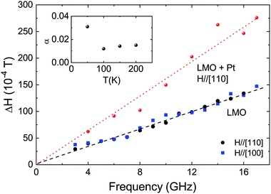
The broadening of the resonance line, characterized by the linewidth ΔH, is a direct measure of the magnetic damping of the system. Damping is a key parameter for spintronic applications since it is closely related to the magnetization switching speed. Ideally, only intrinsic mechanisms contribute to the magnetic damping and, in such cases, the broadening of the ferromagnetic resonance linewidth may be described by a linear dependence on the frequency:41
 | (4) |
The low damping parameter obtained in these PAD-grown LMO thin films opens the possibility to use them as a spin current source, through a spin pumping mechanism. In this phenomenon, a pure spin current is generated in a resonant ferromagnetic (FM) system and pumped into an adjacent non-magnetic (NM) conductor. When the conductor itself exhibits efficient spin–orbit coupling, as in the case of Pt, the spin-pumping mechanism will enhance the intrinsic Gilbert damping of the FM due to the extra dissipation channel of angular momentum because of spin pumping.45 However, the diffusion of the spin-current towards the non-magnetic layer strongly depends on the so-called effective spin-mixing conductance g↑↓ that measures the transparency of the FM/NM interface to spin current and their ability to relax within the non-magnetic layer. In this case, the Gilbert damping may be written as2,46
 | (5) |
4 Conclusions
We have demonstrated that La0.92MnO3 epitaxial thin films grown by polymer-assisted-deposition exhibit low roughness surfaces and magnetic properties fulfilling the requirements to be used as spin source active layers in heterostructures aimed for spintronic devices. Static magnetic and transport measurements show that LMO films are conducting and ferromagnetic, as expected from a double exchange scenario. On the other hand, dynamic magnetic properties were studied via broadband ferromagnetic resonance spectroscopy and we demonstrated the presence of an in-plane four-fold magnetic anisotropy with [110] as an easy in-plane axis. In conjunction with microstructural analysis, this magnetic anisotropy resulted from the strained epitaxial growth of a LMO rhombohedral phase into the underlying cubic SrTiO3 substrate. Magnetic damping exhibits mainly intrinsic Gilbert damping without appreciable contributions from extrinsic mechanisms. In the presence of a 10 nm Pt capping, we have observed a clear enhancement of magnetic damping that may be indicative of effective spin injection into the Pt layer by spin pumping from the LMO film. The effective mixing conductance estimated from the measurements reveals an interface between ex situ chemically grown LMO and Pt with reasonable transparency to spin transport to be suitable for applications in spintronic devices.Conflicts of interest
There are no conflicts to declare.Acknowledgements
We acknowledge financial support from the Spanish Ministry of Science, Innovation and Universities through Severo Ochoa (SEV-2015-04969), HETEROCS (MAT2015-71664-R), SUMATE (RTI2018-095853-B-C21) and SPINCURIOX (RTI2018-099960-B-I00) projects cofinanced by the European Regional Development Fund. This project has received funding from the European Union through the Horizon 2020 research and innovation programme under the Marie Skłodowska-Curie grant agreement No 645658 (DAFNEOX Project) and through the FEDER Program. Hailin Wang acknowledges financial support from the China Scholarship Council (CSC). This work has been performed in the framework of the PhD programme in Materials Science of the Universitat Autònoma de Barcelona, through the China Scholarships Council (CSC)/Universitat Autònoma de Barcelona (UAB) Joint Scholarship. Authors thank Dr B. Bozzo and F. J. Campos for their technical support during magnetic and X-ray diffraction measurements. We acknowledge support of the publication fee by the CSIC Open Access Publication Support Initiative through its Unit of Information Resources for Research (URICI).Notes and references
- N. Locatelli, V. Cros and J. Grollier, Nat. Mater., 2014, 13, 11–20 CrossRef CAS PubMed.
- S. Azzawi, A. T. Hindmarch and D. Atkinson, J. Phys. D: Appl. Phys., 2017, 50, 473001 CrossRef.
- A. Hoffmann and S. D. Bader, Phys. Rev. Appl., 2015, 4, 1–18 CrossRef.
- L. Soumah, N. Beaulieu, L. Qassym, C. Carrétéro, E. Jacquet, R. Lebourgeois, J. Ben Youssef, P. Bortolotti, V. Cros and A. Anane, Nat. Commun., 2018, 9, 3355 CrossRef PubMed.
- Q. Qin, S. He, W. Song, P. Yang, Q. Wu, Y. P. Feng and J. Chen, Appl. Phys. Lett., 2017, 110, 112401 CrossRef.
- M. A. Schoen, D. Thonig, M. L. Schneider, T. J. Silva, H. T. Nembach, O. Eriksson, O. Karis and J. M. Shaw, Nat. Phys., 2016, 12, 839–842 Search PubMed.
- G. Y. Luo, C. R. Chang and J. G. Lin, J. Appl. Phys., 2014, 115, 17C508 CrossRef CAS PubMed.
- G. Y. Luo, M. Belmeguenai, Y. Roussigné, C. R. Chang, J. G. Lin and S. M. Chérif, AIP Adv., 2015, 5, 097148 CrossRef.
- H. K. Lee, I. Barsukov, A. G. Swartz, B. Kim, L. Yang, H. Y. Hwang and I. N. Krivorotov, AIP Adv., 2016, 6, 055212 CrossRef.
- S. Emori, U. S. Alaan, M. T. Gray, V. Sluka, Y. Chen, A. D. Kent and Y. Suzuki, Phys. Rev. B, 2016, 94, 224423 CrossRef.
- D. G. Schlom, APL Mater., 2015, 3, 1–6 Search PubMed.
- I. Safi, Surf. Coat. Technol., 2000, 127, 203–218 CrossRef CAS.
- M. Opel, J. Phys. D: Appl. Phys., 2012, 45, 033001 CrossRef.
- M. A. A. Mamun, A. Haque, A. Pelton, B. Paul and K. Ghosh, IEEE Trans. Magn., 2018, 54, 1–8 Search PubMed.
- A. Haque, A. R. Mahbub, M. Abdullah-Al Mamun, M. Reaz and K. Ghosh, Appl. Phys. A: Mater. Sci. Process., 2019, 125, 1–9 CrossRef CAS.
- Q. X. Jia, T. M. McCleskey, A. K. Burrell, Y. Lin, G. E. Collis, H. Wang, A. D. Li and S. R. Foltyn, Nat. Mater., 2004, 3, 529–532 CrossRef CAS PubMed.
- J. M. Vila-Fungueiriño, B. Rivas-Murias, J. Rubio-Zuazo, A. Carretero-Genevrier, M. Lazzari and F. Rivadulla, J. Mater. Chem. C, 2018, 6, 3834–3844 RSC.
- H. Wang, J. Gazquez, C. Frontera, M. F. Chisholn, A. Pomar, B. Martínez and N. Mestres, NPG Asia Mater., 2019, 11, 41 CrossRef.
- J. M. Vila-Fungueiriño, C. T. Bui, B. Rivas-Murias, E. Winkler, J. Milano, J. Santiso and F. Rivadulla, J. Phys. D: Appl. Phys., 2016, 49, 315001 CrossRef.
- J. Suntivich, H. A. Gasteiger, N. Yabuuchi, H. Nakanishi, J. B. Goodenough and Y. Shao-Horn, Nat. Chem., 2011, 3, 546–550 CrossRef CAS PubMed.
- J. T. Mefford, W. G. Hardin, S. Dai, K. P. Johnston and K. J. Stevenson, Nat. Mater., 2014, 13, 726–732 CrossRef CAS PubMed.
- J. Garcia-Barriocanal, J. C. Cezar, F. Y. Bruno, P. Thakur, N. B. Brookes, C. Utfeld, A. Rivera-Calzada, S. R. Giblin, J. W. Taylor, J. A. Duffy, S. B. Dugdale, T. Nakamura, K. Kodama, C. Leon, S. Okamoto and J. Santamaria, Nat. Commun., 2010, 1, 82 CrossRef CAS PubMed.
- M. Gibert, P. Zubko, R. Scherwitzl, J. Íñiguez and J. M. Triscone, Nat. Mater., 2012, 11, 195–198 CrossRef CAS PubMed.
- X. R. Wang, C. J. Li, W. M. Lü, T. R. Paudel, D. P. Leusink, M. Hoek, N. Poccia, A. Vailionis, T. Venkatesan, J. M. Coey, E. Y. Tsymbal, Ariando and H. Hilgenkamp, Science, 2015, 349, 716–719 CrossRef CAS PubMed.
- J. Roqueta, A. Pomar, L. Balcells, C. Frontera, S. Valencia, R. Abrudan, B. Bozzo, Z. Konstantinović, J. Santiso and B. Martínez, Cryst. Growth Des., 2015, 15, 5332–5337 CrossRef CAS.
- Y. S. Hou, H. J. Xiang and X. G. Gong, Phys. Rev. B: Condens. Matter Mater. Phys., 2014, 89, 64415 CrossRef.
- A. Gupta, T. R. McGuire, P. R. Duncombe, M. Rupp, J. Z. Sun, W. J. Gallagher and G. Xiao, Appl. Phys. Lett., 1995, 67, 3494 CrossRef CAS.
- J. Töpfer and J. B. Goodenough, J. Solid State Chem., 1997, 130, 117–128 CrossRef.
- I. Marozau, P. T. Das, M. Döbeli, J. G. Storey, M. A. Uribe-Laverde, S. Das, C. Wang, M. Rössle and C. Bernhard, Phys. Rev. B: Condens. Matter Mater. Phys., 2014, 89, 174422 CrossRef.
- Y. K. Liu, H. F. Wong, K. K. Lam, C. L. Mak and C. W. Leung, J. Magn. Magn. Mater., 2019, 481, 85–92 CrossRef CAS.
- A. M. Zhang, S. L. Cheng, J. G. Lin and X. S. Wu, J. Appl. Phys., 2015, 117, 1–5 Search PubMed.
- A. Biswas, C.-H. Yang, R. Ramesh and Y. H. Jeong, Prog. Surf. Sci., 2017, 92, 117–141 CrossRef CAS.
- N. Sakai, H. Fjellvag and B. Lebech, Acta Chem. Scand., 1997, 51, 904–909 CrossRef CAS.
- D. Fuchs, L. Dieterle, E. Arac, R. Eder, P. Adelmann, V. Eyert, T. Kopp, R. Schneider, D. Gerthsen and H. V. Löhneysen, Phys. Rev. B: Condens. Matter Mater. Phys., 2009, 79, 1–9 CrossRef.
- F. Sandiumenge, J. Santiso, L. Balcells, Z. Konstantinovic, J. Roqueta, A. Pomar, J. P. Espinós and B. Martínez, Phys. Rev. Lett., 2013, 110, 107206 CrossRef PubMed.
- J. Santiso, J. Roqueta, N. Bagués, C. Frontera, Z. Konstantinovic, Q. Lu, B. Yildiz, B. Martínez, A. Pomar, L. Balcells and F. Sandiumenge, ACS Appl. Mater. Interfaces, 2016, 8, 16823–16832 CrossRef CAS PubMed.
- M. Haidar, M. Ranjbar, M. Balinsky, R. K. Dumas, S. Khartsev and J. Åkerman, J. Appl. Phys., 2015, 117, 17D119 CrossRef.
- S. Mercone, M. Belmeguenai, S. Malo, F. Ott, F. Cayrel, M. Golosovsky, B. Leridon, C. Adamo and P. Monod, J. Phys. D: Appl. Phys., 2017, 50, 045001 CrossRef.
- Å. Monsen, J. E. Boschker, F. Macià, J. W. Wells, P. Nordblad, A. D. Kent, R. Mathieu, T. Tybell and E. Wahlström, J. Magn. Magn. Mater., 2014, 369, 197–204 CrossRef.
- M. Konoto, T. Kohashi, K. Koike, T. Arima, Y. Kaneko, Y. Tomioka and Y. Tokura, Appl. Phys. Lett., 2004, 84, 2361–2363 CrossRef CAS.
- M. Farle, Rep. Prog. Phys., 1998, 61, 755–826 CrossRef CAS.
- M. Belmeguenai, F. Zighem, T. Chauveau, D. Faurie, Y. Roussigné, S. M. Chérif, P. Moch, K. Westerholt and P. Monod, J. Appl. Phys., 2010, 108, 063926 CrossRef.
- F. Mompean, Z. Sefrioui, N. Reyren, T. Feher, M. Varela, C. Leon, J. Santamaria, M. Cabero, K. Nagy, F. Gallego, A. Sander and M. Rio, APL Mater., 2017, 5, 096104 CrossRef.
- M. A. A. Mamun, A. Haque, A. Pelton, B. Paul and K. Ghosh, J. Magn. Magn. Mater., 2019, 478, 132–139 CrossRef.
- Y. Tserkovnyak, A. Brataas and G. E. W. Bauer, Phys. Rev. Lett., 2002, 88, 117601 CrossRef.
- Y. Liu, Z. Yuan, R. Wesselink, A. A. Starikov and P. J. Kelly, Phys. Rev. Lett., 2014, 113, 207202 CrossRef.
- Y. Sun, H. Chang, M. Kabatek, Y.-Y. Song, Z. Wang, M. Jantz, W. Schneider, M. Wu, E. Montoya, B. Kardasz, B. Heinrich, S. G. E. te Velthuis, H. Schultheiss and A. Hoffmann, Phys. Rev. Lett., 2013, 111, 106601 CrossRef PubMed.
| This journal is © The Royal Society of Chemistry 2019 |

